
Product added to cart

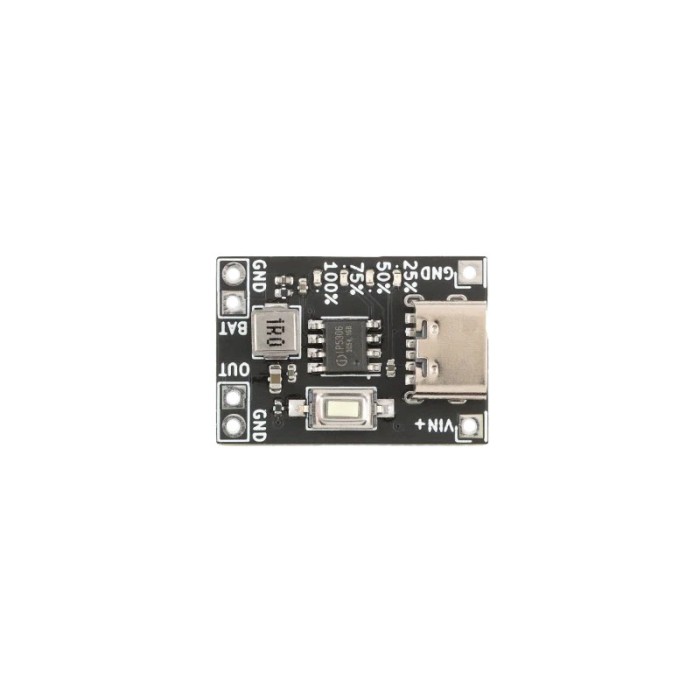
IP5306 Lithium Battery Boost Charging Module 5V/2A with Type-C
$0.9000
In stock
SKU
BAT-03-085
Volume discounts:
- +50 3 % $0.8700
- +100 4 % $0.8600
- +300 7 % $0.8400
- +500 8 % $0.8300
- +1000 10 % $0.8100
Ships in 2-3 business days, then:
Free delivery in 12-15 days by Tracked Economic Shipping on orders over $100.
Free delivery in 7-10 days by Express Shipping on orders over $300.
More shipping info

Shop with confidence Learn More
 Mini Battery Level Indicator 1S Li-ion Previous
IP5306 Boost Charging Module Review
The IP5306 Lithium Battery Boost Charging Module combines single-cell lithium battery charging, a 5V boost converter, power-path management, and a four-LED voltage-based fuel gauge on one compact board. It provides a straightforward power foundation for DIY portable electronics and small utility builds running from a steady 5V supply. It is not suited to microcontrollers that rely on deep sleep, small battery cells that cannot tolerate a 2.1A charge rate, USB Power Delivery setups, or designs requiring a verified continuous-current rating.
Specifications of IP5306 Lithium Battery Boost Charging Module 5V/2A with Type-C
- Charging Efficiency: Up to 91%, with a current of 2.1A
- Discharging Efficiency: Up to 92%, with a current of 2.4A
- Boost Converter: 5V
- Input/Output Protection: Over-current, over-voltage, short-circuit, thermal shutdown
- Fuel Gauge: Voltage-based, with 4 LED indicators
- Standby Current: Less than 100uA
- Interface: Type-C
For builders comparing multi-stage power circuits or multi-cell protection boards, our catalog of battery management system modules offers configurations for specialized power architectures.
IP5306 Module Specifications and 5V Power Behavior
Combining battery management and step-up conversion on one board reduces wiring complexity, but its operating limits still matter. The board lists a 2.1A charge current and a 5V boost converter with a 2.4A discharge-current rating. The title states 5V/2A, while the technical specifications note 2.4A discharge capability. Treat these as separate figures rather than a verified continuous thermal rating, since sustained draw depends heavily on ambient airflow and cell voltage.
| Specification | Listed Value | Why It Matters |
|---|---|---|
| Charging Current | 2.1A | Sets the minimum battery capacity required to prevent cell degradation during charge cycles. |
| Discharge Current | 2.4A (Title: 5V/2A) | Defines peak output capability; continuous draw without heatsinking should be verified in your enclosure. |
| Conversion Efficiency | Up to 91% charge / 92% discharge | Reflects peak operating efficiency; actual efficiency varies across cell discharge voltage and load current. |
| Fuel Gauge | 4 LEDs (Voltage-based) | Provides approximate cell status based on voltage thresholds rather than coulomb-counting runtime estimation. |
| Standby Current | Less than 100uA | Minimizes parasitic drain on the connected lithium cell when the 5V boost output is idle. |
| Input Interface | Type-C | Accepts modern 5V USB cabling for charging, eliminating legacy connectors. |
Need a detailed visual readout and dual standard USB output ports instead of onboard status LEDs? Consider the dual USB power bank module with LCD.
IP5306 Low-Load Shutdown and Battery Safety
The IP5306 architecture includes an automatic standby feature intended for standard power bank operation. When the connected load draws less than roughly 45–50mA, the boost converter shuts off its 5V output after approximately 32 seconds. This will cut power completely to development boards such as an ESP32 or Arduino cycling through deep-sleep states unless an external keep-alive circuit periodically pulses the load current above the shutoff threshold.
Charging safety depends on matching the battery chemistry and capacity to the fixed 2.1A charging stage. Small lithium-polymer cells below 1000mAh generally specify maximum charging rates well below 2A. Feeding high current into an undersized pouch cell risks swelling and thermal failure. Use cells rated for continuous charge currents of 2.1A or higher. The board includes over-current, over-voltage, short-circuit, and thermal shutdown protections, but reverse-polarity protection is not listed. Connecting a battery backward can destroy the IC instantly. For secure, serviceable cell connections, pair the board with an 18650 battery holder to help maintain correct mechanical polarity.
Onboard power-path management allows simultaneous charging and 5V discharging, though transitions between external USB power and battery power may introduce brief voltage fluctuations. Sensitive microcontroller projects should include sufficient output capacitance to prevent unwanted resets during power transitions. Generic modules across this family can also exhibit component variance; bench-test your unit under expected loads before potting or closing the enclosure.
For projects needing adjustable output voltage or a lower, programmable charging current for smaller cells, use a TP4056 module with adjustable boost converter. It operates with a 1A linear charging profile and up to 28V boost capability within a 5W limit.
IP5306 Power Bank Module Alternatives
Module selection comes down to physical footprint, load-current requirements, and whether you need fixed 5V or variable voltages. The table below compares direct and adjacent options for single-cell battery applications.
| Module | Charge Current | Discharge / Output | Key Features | Primary Trade-Off |
|---|---|---|---|---|
| IP5306 Type-C (This board) | 2.1A | 5V @ 2.4A (Title: 2A) | Integrated 4-LED fuel gauge, Type-C interface | Shuts off below ~45–50mA; unverified continuous thermal rating |
| Type-C/USB integrated charge-discharge module | 0–2.1A | 5V @ 2.4A | Dual Type-C and USB-A port interface | Parallel battery connection only; no reverse polarity protection |
| Type-C charge-discharge module with output control | 2A | 5V @ 2A | Key-controlled output and display via K-point pad | Requires external push-button connection for full control |
| 5V 3A charge-discharge module | 3A | 5V @ 3A | Higher current handling, 4-LED power display | Requires cells capable of sustaining a 3A charge rate |
| Compact 5V charge-discharge boost module | 1.2A | 5V @ 450mA continuous | Small 16x12x4.4mm PCB footprint | Limited continuous current; 1–2s switching delay |
| 18650 battery shield with output headers | 0.5A | 5V @ 2A and 3V @ 1A | Onboard battery clip, power switch, breakout pins | Micro USB input only; slow 0.5A charging cycle |
For systems that must keep boost output active under ultra-low sleep currents, development communities discuss a programmable IP5306-I2C variant because register settings can disable auto-shutoff. That specific I2C variant is not part of this product listing.
IP5306 Module Compatibility and First Power Test
This module operates with standard 3.7V nominal (4.2V fully charged) single-cell lithium chemistry configurations. Do not wire cells in series. Basic charge and boost functions operate autonomously, with no external microcontroller programming, drivers, or configuration scripts required.
- Identify the battery pads and inspect polarity markings before soldering. Confirm positive (B+) and negative (B-) terminals.
- Solder the single-cell lithium battery leads to the module with correct polarity. Verify orientation with a digital multimeter before powering on.
- Connect a standard 5V USB source to the Type-C port. The four onboard status LEDs illuminate sequentially to indicate active charging. For benches using older cabling, a Micro USB to USB Type-C adapter allows testing with legacy power supplies.
- Identify the 5V output pads or connector on the received board revision, then verify output voltage with a voltmeter before connecting sensitive logic loads.
- Connect the operating load and observe thermal performance and output stability under active conditions. Avoid using deep-sleep modes as the initial test to prevent confusing auto-shutdown with hardware failure.
For technical reference on internal register maps and baseline timing curves, refer to the manufacturer's IP5306 datasheet.
IP5306 Boost Charging Module Accessories
Safe operation requires compatible external components. The module does not include wiring harnesses, battery cells, or mounting hardware.
- Required: Use a compatible 3.7V single-cell lithium battery rated to accept a 2.1A charging current. Small pouch cells rated for lower charge rates must not be used.
- Required: Provide a regulated 5V USB power source with a Type-C connection.
- Required: Select proper hookup wire suitable for handling up to 2.4A continuous current without excessive resistive drop.
- Recommended: A dedicated 18650 battery holder helps prevent accidental polarity reversal and simplifies cell replacement.
- Recommended: Choose an 18650 lithium battery rated for the system's current profile and verified against manufacturer charge-rate specifications.
- Recommended: Use a Micro USB to USB Type-C adapter when integrating the module into workstations with standard Micro USB infrastructure.
- Optional: Place an external electrolytic or low-ESR ceramic capacitor across the 5V output to smooth brief power transitions during USB source connection changes.
IP5306 Power Bank Module FAQ and Buying Checklist
Is this an IP5306 power bank module?
Yes. It integrates single-cell lithium charging, a 5V boost converter, power-path routing, and an LED battery fuel gauge into one board for portable power tasks.
Can this IP5306 module power an ESP32 in deep sleep?
No. Typical IP5306-family modules turn off their 5V output after roughly 32 seconds when load current drops below approximately 45–50mA. This shuts down microcontrollers drawing microamps in sleep unless an external keep-alive circuit periodically draws current.
Can I charge a small LiPo battery with this module?
Only if the battery manufacturer explicitly permits a 2.1A charging current. Smaller cells, such as 500mAh LiPo pouches, are generally rated for 0.5A to 1A maximum charge rates and will overheat if connected.
Does the Type-C port provide 5V output?
The specification confirms a Type-C interface for 5V input, but whether 5V output is delivered through the Type-C port, dedicated solder pads, or a separate connector depends on the physical board revision received. Inspect the board labels before connecting loads.
Does Type-C mean this IP5306 module supports USB-PD?
No. The module does not support USB Power Delivery protocol negotiation. It operates strictly from standard 5V USB power profiles and will not negotiate 9V, 12V, or higher voltages.
Is the listed 2.4A output current a continuous rating?
The specification states a discharge capability of 2.4A, while the title references 5V/2A. Neither figure represents a guaranteed continuous rating in an unventilated enclosure; verify thermal dissipation under sustained loads.
Does the module protect against reverse battery connection?
No. Reverse-polarity protection is not listed among the board's safeguards. Connecting the battery backward can permanently damage the IC.
What should I choose if I need more output current?
For applications requiring higher throughput, the 5V 3A charge-discharge module lists 3A charging and 3A discharging specifications.
Purchase Decision Summary
- Ideal for: Portable 5V power banks, active sensors, LED indicators, fans, and DIY portable devices that maintain a steady load above 50mA.
- Maybe for: Arduino and ESP32 projects that remain continuously awake or include external circuitry to pulse the load above the auto-shutoff threshold.
- Avoid if: Your load relies on deep-sleep modes, your battery cannot accept a 2.1A charging current, you require USB-PD negotiation, or you need guaranteed uninterrupted output during USB plug/unplug events.
Buying Checklist
- [ ] My battery is a single-cell 3.7V lithium configuration capable of accepting a 2.1A charge rate.
- [ ] I have an 18650 lithium battery or compatible cell ready for assembly.
- [ ] My project load draws more than 50mA continuously or does not enter deep sleep.
- [ ] I understand that the board does not negotiate USB-PD voltage profiles.
- [ ] I have verified that reverse-polarity protection is not present and can verify polarity before wiring.
- [ ] I have accounted for board thermal dissipation if pulling near 2A continuously.
| Chipset | IP5306 |
|---|---|
| Function | Power Bank |
| Supported Battery Type | Lithium |
| Cell Count | 1 |
| Input Voltage (V) | 5V |
| Output Voltage (V) | 5V |
| Output Current (A) | 2.4A |
| Connector | Type-C |
| Max Charging Current | 2.1A |
| Fast Charge Protocol | No |
| USB Connector | USB Type-C |
| Port Configuration | 1x USB Type C |
| Protection | Over-current,Over-voltage,Short-circuit,Thermal shutdown |
| Efficiency (%) | 91% (Charging), 92% (Discharging) |
| Display Type | LED |
| Indicator LEDs | 4 LED indicators |
Write Your Own Review

Please complete your information below to login.
Sign In
Create New Account