
Product added to cart

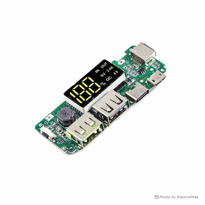
H961 Dual USB 5V 2.4A USB Micro/Type-C Fast Charger Power Bank Module
$1.2500
In stock
SKU
BAT-03-052
Volume discounts:
- +50 4 % $1.2000
- +100 6 % $1.1700
- +300 8 % $1.1500
- +500 10 % $1.1200
- +1000 12 % $1.1000
Ships in 2-3 business days, then:
Free delivery in 12-15 days by Tracked Economic Shipping on orders over $100.
Free delivery in 7-10 days by Express Shipping on orders over $300.
More shipping info

Shop with confidence Learn More
 NIUP11TA NiCd/NiMH Battery Charger Module Previous
H961 Power Bank Module Review and Specifications
The H961 Dual USB Power Bank Module is a compact board that provides standard 5V power for custom battery-powered projects using flat-head 18650 or lithium-polymer cells. It combines dual USB-A output jacks with an integrated digital percentage display on a 6.5 by 2.5 cm board. It suits general 5V bench power and portable device charging, but it does not support Quick Charge or Power Delivery protocol negotiation and has no onboard reverse-polarity protection. For other charging and display configurations, see our battery charging and display modules.
Specifications of H961 Dual USB 5V 2.4A USB Micro/Type-C Fast Charger Power Bank Module
- Input: 5V-2A
- Input interface: micro USB female port, type-c and lightning
- Output interface: 2x standard female port
- Constant current for 1 port: 2.4A
- Dual output current: 5V 1A
- Input voltage B+B-: 3.0 - 4.2V
- Allowed batteries for the module: 18650 flat head lithium batteries or lithium polymer batteries
- BOOST Efficiency: The current is stable below 1 amp and the efficiency is up to 80%.
- Capacity rate: 3.7V / 5V * 80% = 59.2% for mobile battery: mobile battery capacity / total battery capacity * 59.2%
- Reverse polarity protection circuit: No (positive and negative connections should be done carefully.)
- It has overcharge and over discharge protection circuit for lithium battery.
- Button function: press and hold the button after standby, the LED digital screen shows the power bank battery percentage.
- Size: 6.5*2.5cm
- Weight: 10.8G
H961 USB Output, LCD Display, and Battery Capacity Explained
The board has two standard female USB-A output ports. A single port delivers a constant current of 2.4A, meeting standard 5V tablet and phone charging rates. With both ports in use, the rated output current is 5V 1A. Specific phones and basic USB cables may negotiate lower currents, which can prevent devices from drawing the maximum rated power.
The integrated LCD provides real-time visual feedback for output current and battery charge status. After the board enters standby mode, press and hold the side button to reactivate the display and show the remaining battery charge as an integer percentage. This avoids the need to wire separate voltage meters or analog indicator bars into an enclosure.
Battery runtime planning must account for voltage step-up losses. Below 1 amp of output load, the onboard boost circuit operates at up to 80% efficiency. Converting a 3.7V nominal cell voltage to a 5V USB rail at 80% efficiency yields an effective capacity rate of 59.2% (3.7V / 5V * 0.80 = 0.592). A single 18650 lithium battery will deliver approximately 59% of its total cell-level milliamp-hour rating to a 5V USB load.
Need multi-protocol fast charging instead of standard 5V output? The 22.5W 5-Port Bidirectional Power Bank Module provides five USB ports with QC4+, PD3.0, and SCP fast-charging modes.
H961 Power Bank Module Limitations and Safety Notes
The name mentions fast charging, but the H961 module does not support true QC or PD fast-charging protocols. It supplies fixed 5V USB rails. Connected devices that rely on higher-voltage negotiation, such as 9V, 12V, or 20V, will default to standard 5V USB rates.
Reverse-polarity protection is absent. Swapping the positive and negative leads at the B+ and B- terminals will destroy the onboard controller and create a short-circuit risk across your lithium pack. Inspect polarity with a multimeter before making permanent connections. The module incorporates lithium overcharge, over-discharge, over-current, and short-circuit protection circuits, but these features do not replace a properly insulated enclosure, secured battery terminals, and appropriate external fusing.
A few category-level behaviors warrant testing before you finalize your build:
- Low-current shutoff: Generic power bank controllers commonly power down when an attached device draws very low current, typically below 50 to 100 mA. A specific cutoff threshold is not documented for the H961, so microcontrollers running deep-sleep routines must be tested empirically to confirm that the rail remains active.
- Lightning port verification: The PCB physically mounts a Lightning-style connector alongside the Type-C and Micro-USB ports, but third-party testing has not verified its charging performance. Use the Type-C or Micro-USB ports for dependable charging input.
- Hardware revisions: The H961 family spans several generic PCB revisions with minor layout variations. Verify trace routing and pin labels on your specific board.
For compact, single-cell designs where installation safety is paramount, choose the 18650 Power Bank Module (5V 1A), which includes built-in reverse-voltage protection. A covered two-cell battery holder adds mechanical protection and an integrated power switch.
H961 Battery Compatibility and Wiring Requirements
The module accepts 18650 flat-head lithium batteries or lithium-polymer cells with an operating voltage range of 3.0V to 4.2V connected across B+ and B-. Button-top 18650 cells are not specified. Although the board supports multi-cell battery packs, the listing does not define series or parallel limits; operating within the 3.0V to 4.2V window requires a single-cell (1S) parallel configuration.
Recharge the connected pack with a 5V 2A power supply through the Micro-USB, Type-C, or Lightning input interface. Because Lightning charging functionality is unverified in practice, the Micro-USB or Type-C port provides predictable charging times.
The module measures 6.5 by 2.5 cm and weighs 10.8 grams. The bare board does not include cells, wiring, enclosures, or a charging cable. Keep hookup-wire runs to the B+ and B- pads short and sufficiently thick to minimize voltage drops under a 2.4A load. No software, drivers, or firmware configurations are required to operate the board.
An unswitched 18650 battery holder simplifies parallel wiring and provides clean cell retention. Connect an external 5V source with a standard Micro-USB charging cable. For projects that require custom voltage levels rather than dual 5V USB outputs, the TP4056 Charger with Adjustable Boost Converter steps up a single lithium cell to any level between 4.2V and 28V.
H961 Power Bank Module vs Single-Cell and Fast-Charging Modules
Your power-management module depends on the number of outputs, protocol support, and circuit-protection requirements. The table below compares the H961 with alternative boards intended for different power architectures.
| Feature / Requirement | H961 Power Bank Module | Alternative Option | Alternative Details |
|---|---|---|---|
| Output format | Dual USB-A (5V fixed) | TP4056 Charger with Adjustable Boost Converter | Provides an adjustable 4.2V–28V output rail (5W max) instead of fixed USB ports. |
| Single-cell simplicity | Dual output, requires careful wiring | 18650 Power Bank Module (5V 1A) | Single USB-A output limited to 1A, but includes onboard reverse-voltage protection. |
| High-wattage fast charging | Fixed 5V output only (no QC/PD) | LX-Charger 100W/140W Fast Charger | Delivers up to 100W/140W across USB-A and Type-C outputs with PD and PPS protocol support. |
| Multi-port mobile power bank | 2x USB-A output, 5V 1A combined | 22.5W 5-Port Bidirectional Power Bank Module | Provides 5 USB ports, 22.5W bidirectional fast charging, and QC4+/PD3.0/SCP protocol support. |
| Multi-rail development board power | Standard USB power bank outputs | 18650 Battery Charge Shield (5V 2A) | An alternative approach with an integrated battery clip, three 5V 2A ports, and three 3V 1A ports. |
H961 Power Bank Module Accessories and First Power-On Check
A functional power bank requires several supplementary components:
- Required:
- Compatible flat-head cells, such as an 18650 lithium battery or a compatible LiPo pack.
- Mechanical battery retention through an 18650 battery holder or dedicated enclosure.
- A 5V charging lead, such as a Micro-USB charging cable.
- Stranded hookup wire and heat-shrink insulation for the B+ and B- terminals.
- Recommended:
- A covered two-cell battery holder with an integrated power switch for battery isolation.
- An inline fast-blow fuse on the positive battery lead.
- External reverse-polarity protection diodes or a P-channel MOSFET circuit.
- A custom or 3D-printed enclosure matching the 6.5 by 2.5 cm dimensions and port cutouts.
- Optional:
- A periodic keep-alive load circuit if your project experiences unexpected low-current shutdowns.
- External momentary push-button leads routed to the onboard switch pads when mounting in a deep case.
Use this initial power-on sequence to test the module safely:
- Confirm that your battery cell voltages sit between 3.0V and 4.2V using a multimeter.
- Solder the positive battery lead to the B+ pad and the negative lead to the B- pad. Double-check polarity before soldering, as reversed polarity will destroy the board.
- Connect a 5V 2A USB power source to the Micro-USB or Type-C port. Verify that the LCD screen activates and shows the charging state.
- Disconnect the input cable. Press and hold the side button to confirm that the digital display wakes from standby and reports battery percentage.
- Connect a 5V USB load, such as a USB test resistor or test phone, to one of the USB-A ports to verify power output.
H961 Power Bank Module FAQ
Does the H961 power bank module support QC, PD, or true fast charging?
No. The module provides standard 5V output up to 2.4A on a single port and does not implement QC, PD, or PPS charging protocols. Some display-panel revisions include a decorative fast-charge icon, but the board does not negotiate higher voltages.
What batteries work with the H961 power bank module?
The module accepts flat-head 18650 lithium-ion cells or 3.7V lithium-polymer batteries operating within the 3.0V to 4.2V range. Button-top cells and high-voltage chemistries outside this range must not be connected.
Does the H961 module have reverse polarity protection?
No. The board does not include reverse-polarity protection. Connecting the battery leads backwards to the B+ and B- terminals will cause permanent component failure.
What is the H961 module’s USB output current?
The board is rated for a constant current of 2.4A when one USB port is in use. When both USB ports are occupied, the rated output is 5V 1A.
Can the H961 module charge through USB Type-C or Lightning?
The board includes physical Micro-USB, Type-C, and Lightning input connectors rated for 5V 2A input. Third-party testing has not verified charging functionality over the Lightning port, so use the Type-C or Micro-USB port with a Micro-USB charging cable.
What does the H961 LCD display show?
The LCD indicates output current and battery charge level during active use. When the board is in standby, press and hold the side button to display the remaining battery percentage.
Will the H961 power bank module stay on with an ESP32, sensor, or other low-current load?
The module may turn off automatically under low-current loads. Generic power bank controller circuits typically shut down when load current drops below approximately 50 to 100 mA, so continuous operation with sleeping microcontrollers must be verified experimentally. For mixed 5V and 3.3V development boards, the 18650 Battery Charge Shield (5V 2A) provides dedicated power headers and an onboard switch.
Are batteries and a battery holder included?
No. The module is supplied as a bare printed circuit board. You will need compatible batteries, battery holders, wiring, and charging cables separately from our battery charging and display modules catalog.
Purchase Decision Summary
- Ideal for: DIY builders constructing a basic 5V dual-port USB power bank from flat-head 18650 or LiPo cells who want an integrated digital percentage display.
- Maybe for: Powering development boards or USB bench accessories where minimum current draw stays high enough to avoid controller standby shutdowns.
- Avoid if: You require Quick Charge or USB-PD high-voltage negotiation, reverse-polarity protection, or documented continuous low-current output for deep-sleep sensors.
Buying Checklist
- [ ] Battery pack consists of flat-head 18650 or LiPo cells within the 3.0V–4.2V range.
- [ ] Battery polarity is verified before connecting to B+ and B-.
- [ ] Sourced an external 18650 holder, hookup wire, and insulating materials.
- [ ] Verified that the load requires standard 5V power, not QC or PD fast charging.
- [ ] Enclosure plans accommodate the 6.5 by 2.5 cm board footprint, ports, and display.
- [ ] Project does not rely on unverified low-current always-on behavior.
| Compatible With | 18650 flat head lithium batteries or lithium polymer batteries |
|---|---|
| Function | Power Bank |
| Charging Voltage (Pack) | 4.2V |
| Supported Battery Type | Li-ion, LiPo |
| Over-discharge Detection Voltage (per Cell) | Yes |
| Input Voltage (V) | 5V |
| Output Voltage (V) | 5V |
| Output Current (A) | 2.4A |
| Connector | USB, Micro USB, Lightning, USB Type-C |
| Max Charging Current | 2A |
| Fast Charge Protocol | No |
| USB Connector | USB, Micro USB, Lightning, USB Type-C |
| Port Configuration | Dual USB Output |
| Protection | Overcharge,Over discharge,Short circuit,Over current,Reverse polarity warning |
| Efficiency (%) | 80% |
| Display Type | LCD |
| Dimensions (mm) | 65x25mm |
| Weight (g) | 10.8 |
Write Your Own Review

Please complete your information below to login.
Sign In
Create New Account