
Product added to cart

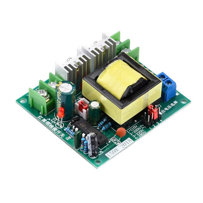
SG3525 DC/AC Step-Up Inverter Module - 150W, 12V to 220V
$3.7500
In stock
SKU
BAT-17-007
Volume discounts:
- +25 4 % $3.5900
- +100 6 % $3.5100
- +300 9 % $3.4300
- +500 11 % $3.3500
- +1000 13 % $3.2700
Ships in 2-3 business days, then:
Free delivery in 12-15 days by Tracked Economic Shipping on orders over $100.
Free delivery in 7-10 days by Express Shipping on orders over $300.
More shipping info

Shop with confidence Learn More
 EGS032 Three Phase Pure Sine Wave Inverter Previous
SG3525 150W Inverter Overview and Specifications
This SG3525 DC/AC step-up module converts an 8V to 14.8V DC source into a high-frequency square-wave or high-voltage DC output. An onboard jumper cap selects 110V, 200V, 220V, or 280V output, making it a flexible power stage for compact DIY projects, bench power-conversion experiments, and low-power off-grid setups. It is intended for intermediate builders who need raw step-up capability rather than an appliance-ready utility power source.
Load suitability is the main consideration when choosing this board. It operates cleanly with purely resistive loads and compatible switch-mode power supply (SMPS) stages. Its output is a high-frequency square wave rather than a standard 50Hz or 60Hz utility sine wave, so it cannot drive motors, fans, compressors, or iron-core transformers. This is one of several specialized DC-AC inverter modules intended for dedicated electronic subassemblies.
Specifications of SG3525 DC/AC Step-Up Inverter Module - 150W, 12V to 220V
- Input Voltage: 12V DC (supports 8V to 14.8V)
- Output Voltage: 110V, 200V, 220V, 280V (selectable by jumper cap)
- Output Power: 150W (up to 200W with cooling)
- Output Waveform: High-frequency square wave or DC
- No-Load Current: 250mA
- Operating Frequency: 27KHz
- Operation Voltage: 12V DC
- Operation Current: Based on load, up to 200W
- Dimensions: ---
- Protection: No built-in protection, external fuse required
- Operating Temperature: -10°C to 85°C
For designers reviewing the underlying PWM controller architecture, internal oscillator circuitry, and totem-pole drive stages, refer to the SG3525 controller datasheet. This reference covers the IC's theoretical operating boundaries, not the thermal limits or board-level specifications of this specific preassembled module.
SG3525 150W Inverter Output, Loads and Limits
The output characteristics of this SG3525 150W inverter determine which devices can run safely. Its step-up transformer and switching circuit produce a high-frequency square wave or high-voltage DC at an operating frequency of 27KHz. Standard AC mains supplies operate at 50Hz or 60Hz with sine waves. An appliance that depends on utility AC line frequency or sinusoidal voltage changes to create a rotating magnetic field will immediately overheat, stall, or fail on this module.
Resistive loads are an ideal match. Incandescent bulbs, resistive wire heaters, and standard AC soldering irons dissipate power based on root-mean-square voltage without being affected by switching frequency or waveform shape. The module also runs compatible SMPS-style loads that internally rectify high voltage directly to DC before stepping down. Verified devices under this topology include laptop chargers, mobile phone chargers, network routers, optical network units (ONUs), and compact television switch-mode adapters. Verify the target adapter's input stage before relying on it, since some complex supplies with active power factor correction (PFC) or line-frequency filter networks may misbehave.
The jumper-selectable header provides taps at 110V, 200V, 220V, and 280V. This allows you to match the rectified DC bus or output voltage to a connected load or down-stage multiplier circuit. Output power is listed at 150W, with up to 200W available with cooling. That 200W figure is not an unconditional continuous rating. Loads above roughly 100W generate rapid thermal buildup in the switching MOSFETs and transformer, requiring a forced-air cooling fan and adequate heatsinking.
Several operational boundaries apply during integration:
- No onboard protection: The board has no reverse-polarity diode, undervoltage lockout, or overcurrent shutdown circuitry. An unmitigated output short or reversed supply immediately results in a blown trace or destroyed transistor.
- Light-load meter error: Standard multimeters cannot accurately read high-frequency square waves. Measuring the output terminals without a load or with a non-true-RMS meter routinely produces wildly inflated or unstable readings. Verify voltage under load with a true-RMS instrument or an oscilloscope.
- Frequency variance: While the website specification sets this board at 27KHz, generic module production runs occasionally vary between 27kHz and 37kHz depending on component batch availability. Verify the frequency of your specific board for sensitive downstream circuits.
For high-frequency square-wave delivery at greater capacity, the 500W Square Wave Inverter Module offers higher sustained power. Inductive loads, motors, and appliances requiring clean grid-style power call for the 500W Pure Sine Wave Inverter Module, which provides true 50Hz sine output and integrated overload protection. Need adjustable voltage and utility frequency with built-in fault defenses? Look at the 600W Modified Sine Wave Inverter Module. For engineers building a custom power inverter stage from the ground up, the EGS002 SPWM Inverter Driver Board supplies pure sine PWM drive signals directly to an external switching topology. To suppress unwanted switching feedback on DC input lines, add an optional Three-stage Composite High-Frequency EMI DC Filter.
SG3525 Inverter Setup and Safety Requirements
Operating a bare-board high-voltage inverter requires appropriate safety and wiring procedures. The module accepts an 8V to 14.8V DC input range, centered on a 12V source. Because it delivers up to 150W, and up to 200W with cooling, input current draw can become substantial. Drawing 150W from a 12V battery pulls more than 12A through the primary leads. Thin hookup wire drops excessive voltage, heats up, and reduces inverter output efficiency.
The board has no internal overcurrent or short-circuit protection, so an external inline fuse on the positive DC input wire is mandatory. Match the fuse to your load and wiring gauge, and place it as close to the power source as possible. If the input is unfused, accidental short circuits at the high-voltage output terminals instantly burn out the power transistors.
Follow this disciplined sequence when preparing the module for operation:
- Configure output voltage: Inspect the jumper cap position and set it to the required voltage tap (110V, 200V, 220V, or 280V) before applying any power. Never move the jumper while the board is energized.
- Prepare cooling: For continuous loads exceeding roughly 100W, affix heatsinks to the switching transistors and position a fan to move air across the board.
- Wire the input: Use thick, low-resistance conductors. For a removable battery connection, use a reliable quick-disconnect such as the XT60 Connector Male-Female Pair for LiPo Battery. Double-check polarity against the board markings; reverse connection will destroy the board.
- Enclose high voltage: The output traces and screw terminals carry dangerous potentials. House the entire assembly inside an insulated, well-ventilated enclosure to prevent accidental contact. For wiring to external equipment, you can terminate the output cleanly with a chassis-mounted Power Cord Plug.
- Initial load test: Connect a known, low-wattage resistive load first, such as a 15W to 40W incandescent bulb. Power on the circuit and observe its behavior.
- Verify under load: Measure output voltage with a true-RMS multimeter or an oscilloscope while the test load is engaged. Gradually increase load demands while checking the switching devices for thermal rise.
Avoid common first-time mistakes:
- Connecting without an input fuse.
- Connecting inductive devices such as box fans or drills.
- Swapping battery polarity.
- Relying on floating no-load multimeter measurements.
- Fabricating custom enclosures or drilling mounting holes before receiving the physical board, since physical dimensions are unlisted in the authoritative data and mounting holes and clearance must be measured directly.
For a fully custom power inverter with integrated overcurrent shutdown and short-circuit protection instead of an unshielded power board, consider the bare SG3525 LM358 Inverter Driver Board. It allows you to implement your own external transformer and switching stage.
SG3525 150W Inverter Uses and Compatibility
This 12V to 220V inverter module fills a specific role in DIY electronics, test fixtures, and non-critical power assemblies. Review the compatibility parameters below to determine whether it suits your application.
| Parameter | Specification / Requirement | Why It Matters |
|---|---|---|
| Input Voltage | 8V to 14.8V DC (12V nominal) | Allows operation from 12V lead-acid, 3S Li-ion, or 4S LiFePO4 packs within safe operating limits. |
| Output Waveform | High-frequency square wave or DC (27KHz nominal) | Restricts loads to resistive and select SMPS adapters; incompatible with 50/60Hz inductive equipment. |
| Output Taps | 110V, 200V, 220V, 280V (jumper selectable) | Enables matching the output voltage to specific regional gear, rectifier buses, or experimental setups. |
| Continuous Power | 150W (up to 200W with cooling) | Sustained power near the maximum rating requires forced air and heatsinks to prevent thermal failure. |
| No-Load Current | 250mA | Defines baseline standby drain when connected to an idle 12V battery system. |
| Protection Hardware | None onboard (requires external fuse) | Builder must supply input fuse, overcurrent safeguards, and correct polarity protection. |
| Compatible Loads | Incandescent bulbs, soldering irons, laptop chargers, mobile chargers, routers, small TVs | Devices must handle high-frequency square wave inputs or rectify input immediately to an internal DC bus. |
| Incompatible Loads | Fans, AC induction motors, refrigerators, compressors, iron-core transformers | Inductive loads overheat quickly and create dangerous back-EMF spikes when fed high-frequency square waves. |
| Enclosure Needs | Insulated, ventilated enclosure required | Output potentials exceed 200V and present an electrical shock risk on bare terminals. |
A frequent hobbyist error is assuming that an appliance rated below 150W will run on any 150W inverter. A 60W desk fan, for example, draws little power, but its shaded-pole or split-phase AC motor will buzz, stall, and quickly overheat on a 27KHz square wave. Stick strictly to resistive heating elements or verified high-frequency-tolerant switch-mode supplies.
Typical real-world projects include field soldering stations running from 12V deep-cycle batteries, emergency illumination setups using standard incandescent bulbs, battery-operated remote networking enclosures running routers and ONU boxes, and high-voltage DC conversion experiments where the output feeds directly into an external rectifier. For high-current battery connections, build your harness with the XT60 Connector Male-Female Pair for LiPo Battery to keep series resistance minimal. If your design requires a different topology, browse the wider range of DC-AC inverter modules.
SG3525 150W Inverter vs 300W–600W Inverter Modules
Choosing an inverter board comes down to waveform type, continuous wattage, output adjustment, and integrated protection. The table below compares this SG3525 module with other assembled inverter boards.
| Module | Waveform | Power Output | Input Voltage | Output Voltage / Freq | Protection Features |
|---|---|---|---|---|---|
| SG3525 150W Inverter Module | High-frequency square wave or DC | 150W (up to 200W with cooling) | 8V to 14.8V DC (12V nom.) | 110V, 200V, 220V, 280V / 27KHz | No built-in protection (external fuse required) |
| 150W DC/AC Step-Up Inverter Module | Square wave (~20 kHz) | 150W | 12V DC | 220V / ~20 kHz | No built-in overload protection |
| 500W Square Wave Inverter Module | High-frequency square wave (~20 kHz) | 500W | 12V DC | Multi-tap (0-160V-220V-380V, 18V) | No built-in protection |
| 300W Modified Sine Wave Inverter | Corrected / modified sine wave | 300W | 12V DC | Adjustable 180–220V / Adj. 50–60Hz | Compact assembled unit |
| 600W Modified Sine Wave Inverter Module | Modified sine wave | 600W | 12V DC | Adjustable 110–220V / Adj. 50–60Hz | Overload, short circuit, over/undervoltage, overcurrent |
| 500W Pure Sine Wave Inverter Module | Pure sine wave | 600W real / 1000W peak | Selectable 12V / 24V / 48V DC | 220V / Preset 50Hz | Short circuit and overload protection |
For an availability alternative with the same core footprint and capacity, the 150W DC/AC Step-Up Inverter Module matches this performance tier. Systems involving standard electrical appliances, motors, or audio electronics that are sensitive to harmonics call for the 500W Pure Sine Wave Inverter Module. The 500W pure sine unit requires startup from an acid battery rather than a standard DC bench supply and lacks internal charging hardware, but it provides clean 50Hz output and full fault-trip defenses.
For mid-tier applications requiring utility frequencies without pure sine wave generation, the 300W Modified Sine Wave Inverter provides adjustable 50Hz to 60Hz switching at 180V to 220V. When higher power and extensive defense features are non-negotiable, choose the 600W Modified Sine Wave Inverter Module, which provides a complete protection package covering shorts, overcurrent, and voltage excursions.
SG3525 150W Inverter FAQ
Can the SG3525 150W inverter run a fan, motor, or compressor?
No. This inverter cannot run inductive motor loads. Its high-frequency square-wave output (27KHz) causes standard AC induction and shaded-pole motors to stall, generate severe core losses, and overheat rapidly. Use an inverter producing standard 50Hz or 60Hz pure sine waves, such as the 500W Pure Sine Wave Inverter Module, for fans, pumps, or motorized appliances.
Is this SG3525 150W inverter pure sine wave?
No. This board produces a high-frequency square-wave or DC output. It does not provide a 50Hz or 60Hz utility pure sine or modified sine waveform and should not be treated as a household wall outlet substitute.
What can this 12V to 220V inverter module power?
It can power purely resistive loads such as incandescent light bulbs and standard soldering irons up to 150W. It also runs compatible switch-mode power supply loads, including laptop power bricks, smartphone chargers, routers, ONU modems, and small television power supplies, provided they rectify AC directly to an internal DC rail.
Is 200W continuous output available?
No. The 200W output figure is conditional on cooling. The standard continuous rating is 150W, and sustained loads above approximately 100W require dedicated heatsinks and forced-air fan cooling to keep operating temperatures within safe bounds.
Does the SG3525 inverter module need a fuse?
Yes, an external input fuse is required. The circuit board has no built-in overcurrent, short-circuit, or reverse-polarity protection, so an appropriately sized fuse on the DC input line is necessary to prevent component destruction during faults.
Why does the output voltage read high when there is no load?
High-frequency square-wave switching generates voltage peaks that confuse conventional averaging multimeters, particularly when there is no load on the circuit. Test the output under a small representative load, using a true-RMS meter or an oscilloscope for accurate voltage validation.
What switching frequency does this inverter use?
The module is specified to run at a 27KHz operating frequency. Because generic production variants sometimes use alternate timing configurations between 27kHz and 37kHz, measure your specific unit with an oscilloscope if your application has tight frequency requirements.
Are the board dimensions available for enclosure design?
No. Exact physical board dimensions and mounting-hole centers are unlisted in the official data. Measure your received board directly before drilling mounting plates or ordering custom enclosures.
SG3525 150W Inverter Buying Decision
This SG3525 150W step-up inverter serves specific power-conversion setups where raw high-voltage conversion is needed without the bulk of a heavy line-frequency transformer. Base your buying decision on these criteria:
- Ideal for: Intermediate builders and hobbyists who need a compact 8V to 14.8V DC step-up module to drive resistive loads, test compatible switch-mode chargers, build isolated DC-bus bench experiments, or demonstrate SG3525 high-frequency switching stages.
- Maybe for: Low-power off-grid emergency kits or portable 12V battery packs where the user is prepared to add their own inline fuse, robust input cabling, cooling hardware, and a safe, non-conductive high-voltage enclosure.
- Avoid if: You need to run fans, AC motors, compressors, audio hardware, or transformer-based equipment; you need certified household backup power; or you require a plug-and-play solution with built-in short-circuit and overcurrent protection.
For applications requiring grid-like sinusoidal AC power, select the 500W Pure Sine Wave Inverter Module instead. For a packaging or sourcing alternative for this exact circuit, see the 150W DC/AC Step-Up Inverter Module. To review other power-conversion technologies, browse the full collection of DC-AC inverter modules.
Buying Checklist
- [ ] My power source is 12V DC and stays between 8V and 14.8V under load.
- [ ] My target load is resistive (bulb, iron) or a compatible SMPS device, not an inductive motor or fan.
- [ ] My device functions on a high-frequency square wave or DC, rather than requiring a 50Hz/60Hz sine wave.
- [ ] My continuous power demand stays within the 150W listed limit.
- [ ] I have a fan and heatsink prepared if running loads above roughly 100W up to the 200W cooling limit.
- [ ] I have an external inline fuse and holder ready for the 12V input wire.
- [ ] I have high-current wire and reliable battery connectors, such as an XT60 connector pair.
- [ ] I have an insulated, touch-safe enclosure to isolate high-voltage output terminals.
- [ ] I will wait to measure the received physical board before designing an enclosure.
- [ ] I will verify voltage under load using a true-RMS meter or oscilloscope.
Write Your Own Review

Please complete your information below to login.
Sign In
Create New Account