
Product added to cart

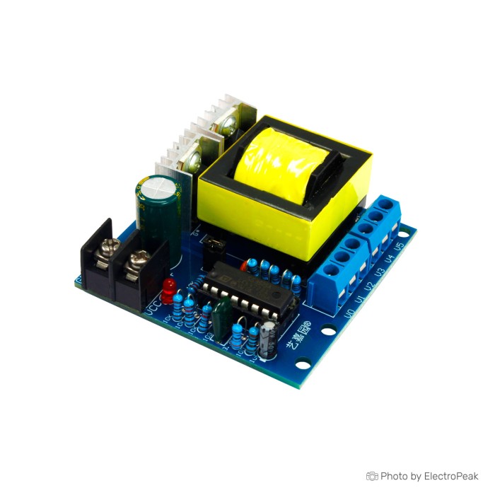
DC/AC Step-Up Inverter Module - 150W, 12V to 220V
$3.7500
In stock
SKU
BAT-02-099
Volume discounts:
- +25 4 % $3.6000
- +100 6 % $3.5300
- +300 8 % $3.4600
- +500 10 % $3.3800
- +1000 12 % $3.3100
Ships in 2-3 business days, then:
Free delivery in 12-15 days by Tracked Economic Shipping on orders over $100.
Free delivery in 7-10 days by Express Shipping on orders over $300.
More shipping info

Shop with confidence Learn More
 EGS002 Pure Sine Wave Inverter SPWM Driver Board Previous
150W 12V to 220V Inverter Module Review
The BAT-02-099 is a compact, exposed step-up power board that converts low-voltage DC into high-voltage AC for bench experiments and custom power circuits. It operates from a 10 to 15V DC input range and delivers up to 150W across multiple transformer taps, including nominal 110V, 175V, 200V, and 220V outputs. Its output is an approximate 20 kHz square wave, not standard 50 Hz or 60 Hz sinusoidal AC, so it is not a direct replacement for a household mains outlet. This is a lightweight switching block for builders working with high-frequency power conversion, specialized test benches, and dedicated resistive loads.
High-voltage conversion on an unhoused board demands careful installation safety. The module has no overload protection, so an accidental short circuit or sustained excessive load will destroy components without external fuses. For engineers designing specialized power supplies or hobbyists comparing DC-AC inverter modules, this board offers a flexible multi-tap platform when used with proper external enclosures and current-limiting provisions.
Specifications of DC/AC Step-Up Inverter Module - 150W, 12V to 220V
- Input voltage range: 10 to 15V DC
- Output voltage: V0--V2 = 110V
- Output voltage: V0--V3 = 175V
- Output voltage: V0--V4 = 200V
- Output voltage: V0--V5 = 220V
- Output voltage: V5--V4 = 20V
- Output voltage: V5--V3 = 45V
- Output voltage: V5--V2 = 110V
- Output voltage: V4--V3 = 28V
- Output voltage: V4--V2 = 90V
- Output voltage: V3--V2 = 62V
- Output power: up to 150W
- Output waveform: square wave
- Output frequency: approximately 20 kHz
- Input protection: no overload protection
- Efficiency: high efficiency in DC to AC conversion
- Dimensions: 61x58mm
150W 12V to 220V Inverter Module Specifications Explained
This board needs to be considered beyond its nominal figures. Its transformer has multiple intermediate windings, so the output voltage depends entirely on the physical terminal pair selected. The listed values are nominal; output voltage changes with both supply voltage and connected load on matching family variants. Rather than providing a regulated mains rail, the module operates as an open-loop high-frequency oscillator and step-up transformer.
| Specification | Listed Value | Why It Matters |
|---|---|---|
| Input Voltage | 10 to 15V DC | Accommodates standard 12V lead-acid batteries, 3S/4S lithium configurations, or heavy-duty bench supplies, but requires adequate current delivery without voltage sag. |
| Output Power | Up to 150W | Represents peak output capability. Continuous operation near this limit is unverified without supplemental forced-air or heatsink cooling. |
| Output Waveform | Square wave | Produces fast switching edges with high harmonic content, preventing direct use with AC motors, traditional transformers, or inductive household equipment. |
| Output Frequency | Approximately 20 kHz | Operating well above audible and line frequencies allows a compact transformer core, but standard 50/60 Hz equipment cannot process this switching frequency. |
| Voltage Selection | Multi-tap terminals (V0 to V5) | Permits tailored AC delivery between 20V and 220V across differential pairings, useful for matching specific custom rectification or load stages. |
| Input Protection | No overload protection | The board will not self-protect during excessive loading, overtemperature, or short-circuit events; an inline fast-blow fuse is mandatory. |
| Board Footprint | 61x58mm | Compact physical footprint for embedding into custom enclosures, though external clearance and terminal isolation must be factored into the enclosure design. |
Physical board revisions can vary across batches, so always confirm terminal locations against the silk-screen markings on the delivered board before wiring. For applications that rely on jumper-selectable taps rather than hardwired screw-terminal differentials, the SG3525 150W Inverter Module is an alternative 150W inverter module with different listed output selections, including 110V, 200V, 220V, and 280V jumper settings.
150W 12V to 220V Inverter Module Limitations and Load Compatibility
The main limitation is the combination of a square wave and an approximate 20 kHz operating frequency. The module is completely unsuitable for AC induction motors, ceiling fans, refrigeration compressors, or standard 50/60 Hz iron-core power transformers. High-frequency square-wave drive causes massive eddy-current losses, rapid thermal buildup, and potential motor burnout within minutes in inductive loads.
Modern switch-mode power supplies (SMPS) behave unpredictably on high-frequency square waves. In technical evaluations of closely matching family modules, simple phone chargers started because their input stage promptly rectifies the AC signal to DC. Complex laptop adapters and flat-screen television power supplies, by contrast, failed to start, often because of high-frequency impedance issues, active PFC stage faults, or front-end filter resonance. Do not assume electronic-load compatibility from wattage ratings alone.
| Load Category | Compatibility Status | Technical Consideration |
|---|---|---|
| Resistive loads (incandescent lamps, heating elements) | Compatible within limits | Pure resistance functions independently of frequency, provided load wattage remains well below the thermal limits of the board. |
| Inductive equipment (motors, fans, pumps) | Incompatible | High-frequency switching causes extreme core saturation, massive heating, and motor failure. |
| Iron-core mains transformers | Incompatible | Designed specifically for 50/60 Hz; high-frequency drive causes destructive eddy currents and insulation stress. |
| Switch-mode supplies (laptops, TVs) | Incompatible / Untested | Active PFC circuits and EMI filter networks frequently fail or block startup on 20 kHz square waves. |
| Compact USB chargers | Variable | May function if using simple diode-bridge inputs, but generates considerable electrical noise. |
For off-grid electronics that require clean line-frequency power, use the 500W Pure Sine Wave Inverter Module for 50Hz pure-sine output with compatible AC loads. If broader utility compatibility calls for modified sine wave power, consider the 600W Modified Sine Wave Inverter Module, an adjustable 50–60Hz modified-sine inverter module with integrated protections. For custom inverter setups requiring DC-bus noise suppression, a Three-stage Composite High-Frequency EMI DC Filter provides project-specific DC-side EMI filtering to prevent high-frequency transients from back-feeding into the DC source.
150W 12V to 220V Inverter Module vs Pure Sine and High-Frequency Inverter Modules
Inverter-board selection comes down to power headroom, output waveform, operating frequency, and onboard circuit protection. This 150W module is compact and provides multi-tap voltage routing for bench experimentation. Other platforms in the DC-AC inverter modules catalog provide specific wave-shaping for sensitive equipment.
| Model | Stated Power | Waveform | Frequency | Protection Features | Key Use Case |
|---|---|---|---|---|---|
| 150W 12V to 220V (This Board) | Up to 150W | Square wave | ~20 kHz | None | Multi-tap high-frequency experiments, resistive test loads |
| 500W High-Frequency Step-Up | 500W | Square wave | ~20 kHz | None | High-power multi-tap step-up conversion for non-inductive loads |
| 300W Modified Sine Wave | 300W | Modified sine | 50–60 Hz (adjustable) | Not stated | Basic lower-power utility AC power from 12V batteries |
| 600W Modified Sine Wave | 600W | Modified sine | 50–60 Hz (adjustable) | Multiple built-in | Mobile power, field service, portable off-grid systems |
| 500W Pure Sine Wave | 500W (600W real / 1000W peak) | Pure sine | 50 Hz | Lead-acid battery dedicated | Motors, audio systems, sensitive electronics, line-frequency tools |
Need higher current delivery while retaining high-frequency multi-tap flexibility? The 500W High-Frequency Step-Up Inverter Module is a higher-power high-frequency inverter module alternative. Where standard household frequencies are non-negotiable for general utility applications, the 300W Modified Sine Wave Inverter Module provides a compact 300W 50–60Hz modified-sine alternative that matches standard appliance line requirements far better than a 20 kHz square wave.
150W 12V to 220V Inverter Module Installation and Accessories
Safe operation requires external mechanical and electrical protection. The PCB has exposed traces carrying over 200V peak potentials, so it must always be installed inside a rigid, nonconductive enclosure. Never leave the board exposed on a powered workbench. Shield all output terminals and high-voltage leads against accidental contact.
Low-voltage power feeds require heavy-gauge copper wiring. Delivering 100W to 150W from a 12V rail draws between 8A and 14A continuously. Thin jumper wires will produce significant voltage drop and overheat rapidly. Place an external fast-acting fuse directly beside the positive battery or power-supply terminal to guard against fire caused by an output short circuit or component failure.
- Required: Stable 10 to 15V DC power source or battery capable of sustained 10–15A discharge.
- Required: Heavy-gauge DC input wire (14 AWG to 12 AWG minimum) cut as short as practical.
- Required: External fast-acting fuse and fuse holder (15A to 20A rating) on the primary positive lead.
- Required: Nonconductive, ventilated enclosure with proper creepage distance around high-voltage pins.
- Required: High-voltage insulated output leads with strain relief and shrouded connections.
- Recommended: Maintain low contact resistance during high-current battery operation with a verified DC battery connection using an XT60 Connector Male-Female Pair for LiPo Battery.
- Recommended: Use active cooling via a 12V DC cooling fan when planning sustained loads above 75W–100W.
- Optional: Add inline filtration using a Three-stage Composite High-Frequency EMI DC Filter to suppress RF noise traveling upstream along the DC supply lines.
150W 12V to 220V Inverter Module Quick Start Check
Before wiring a high-demand load, perform a controlled initial bench check to confirm terminal mapping and board function. No software, drivers, IDEs, or firmware setup is involved; operation is entirely hardware-based.
- Inspect board markings: Carefully read the silkscreen labels on the delivered PCB to locate input terminals (+ and -) and verify the high-voltage output tap designations.
- Select output pins: Identify the correct terminal pair for your target voltage (for example, V0 and V5 for 220V) and connect high-voltage insulated test leads.
- Attach test load: Wire a low-wattage, known-compatible resistive load (such as a 15W to 25W incandescent test bulb) across the selected output pair.
- Prepare DC input: Install an external fast-acting inline fuse on the positive supply line. Connect the input to a 12V DC power source using a robust connection, such as an XT60 Connector Male-Female Pair for LiPo Battery.
- Verify polarity: Check DC input polarity again before energizing; reverse polarity will damage switching components.
- Power and monitor: Apply power, observe the test load, and listen for high-frequency squeal. Cut DC power immediately if any component emits smoke, develops excessive heat, or arcs.
- Measurement check: When measuring output voltage, use a wideband true-RMS meter or an oscilloscope with an appropriate high-voltage probe. Standard multimeters calibrated for 50/60 Hz will register inaccurate or erratic voltages when sampling a 20 kHz square wave.
150W 12V to 220V Inverter Module FAQ
Is this a normal 220V, 50Hz household inverter?
No. This board outputs an approximate 20 kHz square wave rather than standard 50 Hz or 60 Hz sinusoidal AC. It cannot serve as an all-purpose household mains replacement and will damage line-frequency consumer appliances.
Can this 150W 12V to 220V inverter module run a motor, fan, pump, or transformer?
No. Inductive loads and conventional iron-core transformers will overheat and fail rapidly because of excessive eddy currents from the 20 kHz square wave. Inductive motors require pure sine wave inverters operating at 50 Hz or 60 Hz.
Can it power a laptop, television, LED lamp, or phone charger?
Compatibility cannot be assumed from device wattage. In bench evaluations of closely matching boards, simple phone chargers functioned, while laptop power bricks and television power stages refused to start entirely. Complex switch-mode supplies with active power factor correction generally reject high-frequency square-wave inputs.
Is the 150W output rating suitable for continuous operation?
The 150W rating is an upper-limit capacity. Sustained operation near 150W without forced-air cooling will cause rapid thermal saturation of the transformer and switches. Keep extended operation at conservative wattages or pair it with active fan cooling.
What 12V power supply does this inverter board need?
It requires a robust 10 to 15V DC power source capable of delivering 10A to 15A continuous current without drooping. Small wall-plug adapters will brown out under load and prevent the inverter from running.
Does this inverter module have overload or short-circuit protection?
No. The module has no integrated overload, overtemperature, or short-circuit protection. Install an external fast-acting inline fuse on the DC input line to reduce fire hazard during fault conditions.
Are the listed output voltages regulated?
No. Output voltages are unregulated open-loop transformer taps. Output voltage will fluctuate with input battery level and the resistance of the attached load.
Can I measure the output with a normal multimeter?
Standard multimeters are calibrated strictly for 50 Hz to 400 Hz sinusoidal waveforms and will report erroneous readings at 20 kHz. Accurate measurement requires an oscilloscope with high-voltage differential attenuation or a true-RMS meter rated for wideband high-frequency AC.
Do I need a heatsink and fan?
Yes, auxiliary cooling is necessary when you intend to run sustained loads above 75W or operate the module continuously inside an enclosed project box.
Are all 150W blue inverter boards the same?
No. Generic step-up inverter boards have distinct revisions, varied switching frequencies (often ranging from 20 kHz to 40 kHz), different transformer tap configurations, and differing driver ICs. Always verify the printed silkscreen on your specific board before making connections.
For custom pure-sine inverter designs requiring external power MOSFET stages, consider the EGS002 Pure Sine Wave Driver Board for building a custom pure-sine inverter design. For a modular push-pull power stage built from discrete semiconductors, the SG3525 LM358 Driver Board acts as an external MOSFET inverter-driver stage.
Purchase Decision Summary
Ideal for: Experienced electronics hobbyists, technicians, and experimenters who need an inexpensive, multi-tap high-voltage step-up board to drive verified resistive loads, high-frequency rectification stages, or educational bench setups from a 10–15V DC source.
Maybe for: Enclosed, fused laboratory prototypes requiring compact DC-to-AC stepping, provided load compatibility with 20 kHz square waves is thoroughly verified beforehand.
Avoid if: You need plug-and-play household mains power, want to operate induction motors, fans, pumps, audio equipment, or sensitive consumer electronics, require certified enclosures, or lack the safety equipment and measurement tools needed to handle uninsulated high voltages safely.
Buying Checklist
- Confirm your load is purely resistive or specifically rated to handle an approximate 20 kHz square wave.
- Confirm that the equipment to be powered is not an induction motor, fan, pump, or line-frequency transformer.
- Ensure your DC power supply or battery can supply between 10A and 15A continuous current at 10 to 15V DC.
- Obtain heavy-gauge DC wire and an inline fuse holder with a 15A–20A fast-acting fuse.
- Prepare a nonconductive, ventilated enclosure to isolate exposed 220V contacts and high-voltage terminals.
- Ensure you have access to wideband true-RMS measurement equipment or an oscilloscope for accurate voltage checks.
- Verify that your target voltage matches one of the specific output terminal pairs (V0 through V5).
- Select a 50/60 Hz pure-sine or modified-sine module if standard utility AC appliance operation is required.
Write Your Own Review

Please complete your information below to login.
Sign In
Create New Account