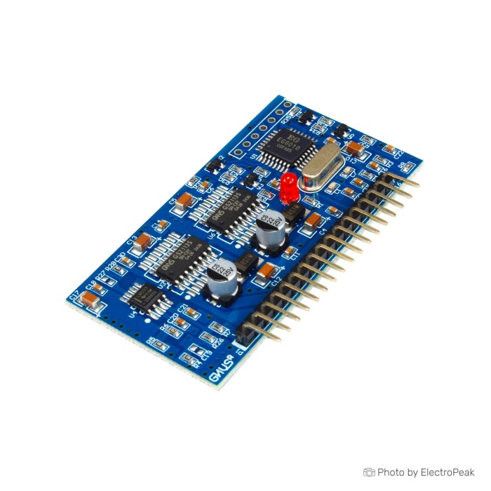
The EGS002 Pure Sine Wave Inverter SPWM Driver Board is a fundamental component in pure sine wave inverter systems. It facilitates the generation of high-quality AC power from DC sources by employing Sinusoidal Pulse Width Modulation (SPWM) techniques.

This board is popular among DIY enthusiasts and professionals for its efficiency and effectiveness in producing clean and stable sine wave outputs, finding applications in renewable energy systems, UPS units, and motor control systems.
Key features of EGS002 Pure Sine Wave Inverter SPWM Driver Board
The EGS002 Pure Sine Wave Inverter SPWM Driver Board boasts several key features that make it a preferred choice for inverter applications:
- Sinusoidal Pulse Width Modulation (SPWM): Utilizes SPWM technique to generate high-quality sine wave output, ensuring low harmonic distortion and smooth power delivery.
- Integrated Microcontroller: Incorporates a microcontroller or specialized IC for precise control and generation of SPWM signals, allowing for flexible customization and optimization of inverter performance.
- High Efficiency: Designed for efficient power conversion, minimizing energy losses during the DC to AC conversion process, thus maximizing overall system efficiency.
- Overload and Short Circuit Protection: Equipped with built-in protection mechanisms to safeguard the inverter and connected devices against overloads and short circuits, enhancing system reliability and longevity.
- Wide Voltage Input Range: Supports a broad range of input voltages, making it compatible with various DC power sources such as batteries, solar panels, and wind turbines.
- Compact Design: Compact and space-saving form factor, facilitating easy integration into inverter systems and making it suitable for both residential and commercial applications.
- User-Friendly Interface: Provides user-friendly interfaces for adjusting parameters and monitoring system status, allowing for convenient setup and operation.
- Versatile Applications: Suitable for a wide range of applications including off-grid power systems, backup power supplies, solar energy systems, and motor control applications.
Overall, the EGS002 Pure Sine Wave Inverter SPWM Driver Board combines advanced features with robust design to deliver reliable and high-performance inverter solutions for various power conversion needs.
Specifications of EGS002 Pure Sine Wave Inverter SPWM Driver Board:
Input voltage range: 5V & 12V power supply
Output Frequency: Adjustable output frequency, commonly ranging from 50Hz to 60Hz, to match the standard frequency of AC power systems.
Control Method: Utilizes Sinusoidal Pulse Width Modulation (SPWM) technique for waveform generation, along with lineage control. Has voltage, current and temperature feedback
PWM carrier frequency: 23.4KHz
Protection Features: Built-in overvoltage, under voltage, overcurrent, overheating protection circuit
Control Interface: Has serial communication to adjust the output voltage, frequency and other parameters
Operating Temperature: 0°C to 50°C
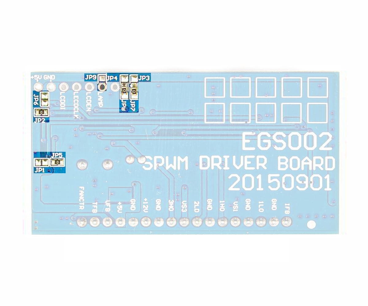
What purpose are the jumpers installed on the board?
There are 9 jumpers on the EGS002 Pure Sine Wave Inverter SPWM Driver Board PCB. You can use them to adjust the output of the inverter.

- Frequency select (JP1 & JP5): JP1 When JP1 is short, it selects AC output frequency at 60Hz JP5 When JP5 is short, it selects AC output frequency at 50Hz
- Soft Start Mode select (JP2 & JP6): JP2 When JP2 is short, it enables 3 seconds soft start mode JP6 When JP6 is short, it disables soft start mode
- Dead Time Select (JP3 & JP4 & JP7 & JP): JP3 When JP7 and JP8 are short, dead time is 300ns. When JP3 and JP8 are short, dead time is 500ns. When JP4 and JP7 are short, dead time is 1.0us. When JP3 and JP4 are short, dead time is 1.5us.
- Backlight Enable (LED+): When JP9 is short, LCD backlight is on When JP9 is open, LCD backlight is off
The driver board’s jumperJP5, JP2, JP7 and JP8 are shorted as default setting, corresponding to 50Hz output, soft start mode on, 300nS dead time. Users can change these based on their needs.
Warning: Jumper of the same function CANNOT be short circuited at the same time. (For example: JP1 and JP5 cannot be short at the same time.)
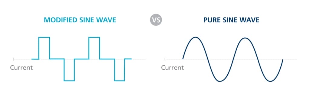
Modified or Pure Sine Wave Inverter? Which one is suitable for you?
The choice between a modified sine wave inverter and a pure sine wave inverter depends on the specific requirements of your application and the types of devices you intend to power.

- Modified Sine Wave Inverter:
- Suitable for basic electronic devices and appliances such as lights, fans, and simple electronics.
- Typically more affordable compared to pure sine wave inverters.
- May produce a buzzing sound in audio equipment and can potentially cause interference with sensitive electronics.
- Not compatible with some types of equipment including certain motor-driven appliances, power tools, and medical devices.
- Ideal for applications where cost is a primary concern and where the equipment being powered is tolerant to waveform imperfections.
- Pure Sine Wave Inverter:
- Produces a waveform that closely resembles utility grid power, providing clean and stable power output.
- Compatible with all types of electronic devices and appliances, including sensitive equipment such as computers, audio/video equipment, and medical devices.
- Eliminates potential buzzing sounds and interference, ensuring optimal performance of connected devices.
- Suitable for powering a wide range of equipment including motor-driven appliances, power tools, and appliances with variable speed motors.
- Generally more expensive than modified sine wave inverters due to the complexity of waveform generation.
- Recommended for applications where device compatibility, performance, and reliability are paramount, especially for sensitive electronics or equipment with specific power requirements.
In summary, if you have basic power needs and are looking for a cost-effective solution, a modified sine wave inverter may suffice. However, if you require clean and stable power output for sensitive electronics or if you need compatibility with a wide range of devices, investing in a pure sine wave inverter is the preferable choice despite the higher cost.
Warnings to keep in mind when using EGS002 Pure Sine Wave Inverter SPWM Driver Board.
When using the EGS002 Pure Sine Wave Inverter SPWM Driver Board, it's important to keep the following warning points in mind to ensure safety and optimal performance:
- Electrical Shock Hazard: The inverter board operates at high voltages, presenting a risk of electrical shock. Always disconnect the power supply and discharge any capacitors before working on the board or making connections.
- Heat Dissipation: The inverter board may generate heat during operation, especially at higher power levels. Ensure adequate ventilation and cooling to prevent overheating, which can degrade performance and lead to component failure.
- Overload Protection: Avoid overloading the inverter beyond its rated capacity, as it can cause overheating, voltage drops, and potential damage to the components. Use appropriate fuses, circuit breakers, or overload protection devices to safeguard the inverter and connected devices.
- Short Circuit Risk: Take precautions to prevent short circuits when wiring the inverter board to the power source and load. Use proper insulation, secure connections, and suitable wiring gauges to minimize the risk of short circuits, which can damage the board and pose a fire hazard.
- Proper Grounding: Ensure the inverter board is properly grounded according to the manufacturer's recommendations. Poor grounding can result in electrical noise, interference, and safety hazards.
- Voltage Compatibility: Verify that the input voltage of the inverter board matches the voltage of the DC power source to prevent damage to the board and connected devices. Avoid connecting incompatible voltage sources.
- Manufacturer Guidelines: Follow the manufacturer's instructions, recommendations, and safety guidelines provided in the user manual or documentation accompanying the inverter board. Failure to do so may result in damage to the board, connected devices, or personal injury.
FAQs about EGS002 Pure Sine Wave Inverter SPWM Driver Board
What is the output frequency range of the EGS002 board?
The output frequency of the EGS002 board is adjustable between 50Hz or 60Hz, which matches the standard frequency of AC power systems in most regions. In order to choose between these two frequencies, there are two jumpers on the PCB named JP1 and JP5. When JP1 is short, it selects AC output frequency at 60Hz. And when JP5 is short, it selects AC output frequency at 50Hz.
Can the EGS002 board be used for solar power systems?
Yes, the EGS002 board can be used in solar power systems as an integral component of the inverter to convert DC power from solar panels into AC power suitable for residential or commercial use.
Is the EGS002 board suitable for DIY projects?
Yes, the EGS002 board is commonly used in DIY projects by electronics enthusiasts and hobbyists for building pure sine wave inverters. It offers flexibility, reliability, and ease of integration into various power conversion systems.
What is the maximum output power supported by the EGS002 board?
The maximum output power handling capacity of the EGS002 board varies depending on the design and components used but typically ranges from a few hundred watts to several kilowatts.
Where can I find the user manual or documentation for the EGS002 board?


Please complete your information below to login.
Sign In
Create New Account