

In this tutorial, you will learn how to use the passive infrared (PIR) sensor modules with Arduino. PIR modules play an important role in motion detection technology, security systems, smart lighting, home automation, etc. Whether you’re a beginner or an experienced developer —looking to improve your projects— this tutorial will give you a thorough understanding of PIR modules, enabling you to apply them skillfully in your applications.
What You Will Learn
- The structure and function of PIR sensors
- How to use a PIR sensor module independently
- How to use a PIR sensor module with Arduino
What Is a PIR Sensor?
A passive infrared sensor module is a type of motion detection sensor that uses the pyroelectric effect to detect changes in the infrared radiation.
All living beings and objects emit infrared radiation that is invisible to human eyes. Some of them emit these types of waves and others reflect them. PIR sensors measure the intensity of this radiation to detect movement.
Most PIR sensors are structured as follows:
- Pyroelectric sensor: The primary component of the PIR sensor module, which is usually made of pyroelectric materials such as lithium tantalate or lithium niobate. Infrared radiation on this sensor generates a voltage at the output.

- Lens: PIR sensors often include a lens, such as a Fresnel lens, that focuses the infrared radiation onto the pyroelectric sensor. The lens’s design helps to increase the field of view and the sensitivity of the sensor.

- Motion detection circuit: The electrical charges generated by the pyroelectric sensor are processed by a detection circuit, which interprets the signals and changes the state based on the detected movement.
PIR Sensors: How They Work
The working principle of a PIR sensor is based on the pyroelectric effect, which generates a potential difference (voltage) at the sensor’s output. Here’s a step-by-step explanation of how this sensor works:
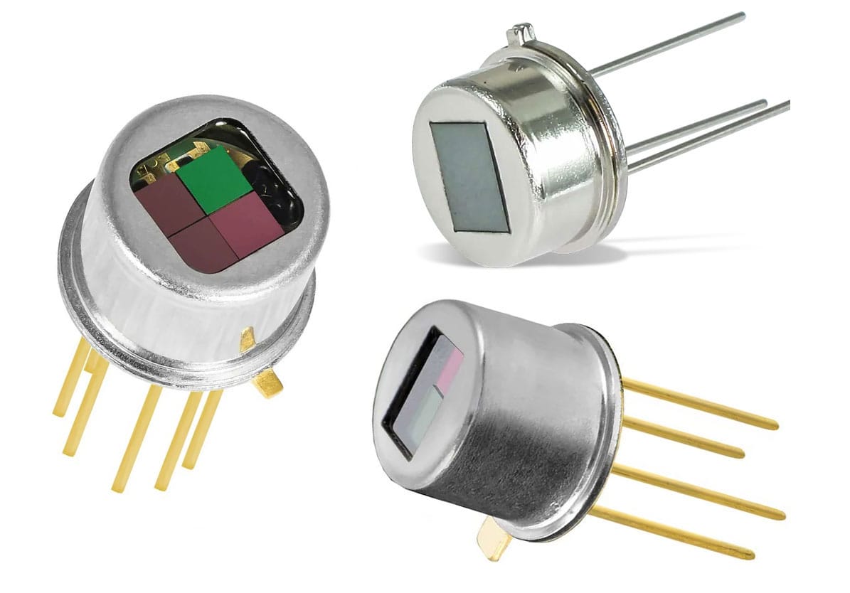
- Pyroelectric materials: As mentioned earlier, the pyroelectric material is the key part of a PIR sensor and it becomes bipolar when exposed to infrared beams. This sensor usually has one or more sensitive areas exposed to the environment (image below). If the sensor is a 2-channel type, it has two separate infrared sensor electrodes, one of which generates a positive output, and the other generates a negative output.
- Electric charge generation: Infrared radiation in the environment generates electric charges on the surfaces of the PIR sensor. The voltage difference generated at the sensor’s output depends on the intensity of infrared radiation.
- Detection circuit: The voltage generated by the sensor is amplified by an electronic circuit. For example, in 2-channel sensors, the electrodes are wired in such a way to normally cancel each other out. This is because we want to detect changes in the infrared radiation (not the constant value in the environment).
When one of the two electrodes senses more or less infrared radiation than the other, the output will not be zero.
In short, a PIR sensor converts the infrared radiation changes —caused by temperature changes in its environment— into an electrical signal. This electrical signal is then processed by a detection circuit to perform specific actions or responses in various applications, such as motion detection and security systems.
Fresnel Lenses on PIR Modules
There is a white frame on PIR modules called the Fresnel lens. This lens plays an important role in the performance of a PIR sensor, as it focuses and increases the detection ability of the sensor.
In the image below, you can see the structure of a Fresnel lens.
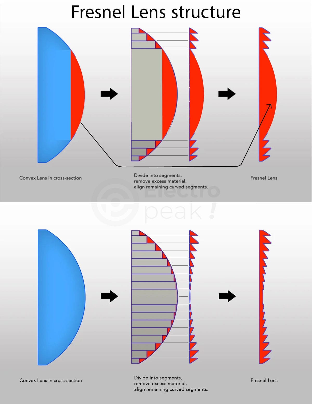
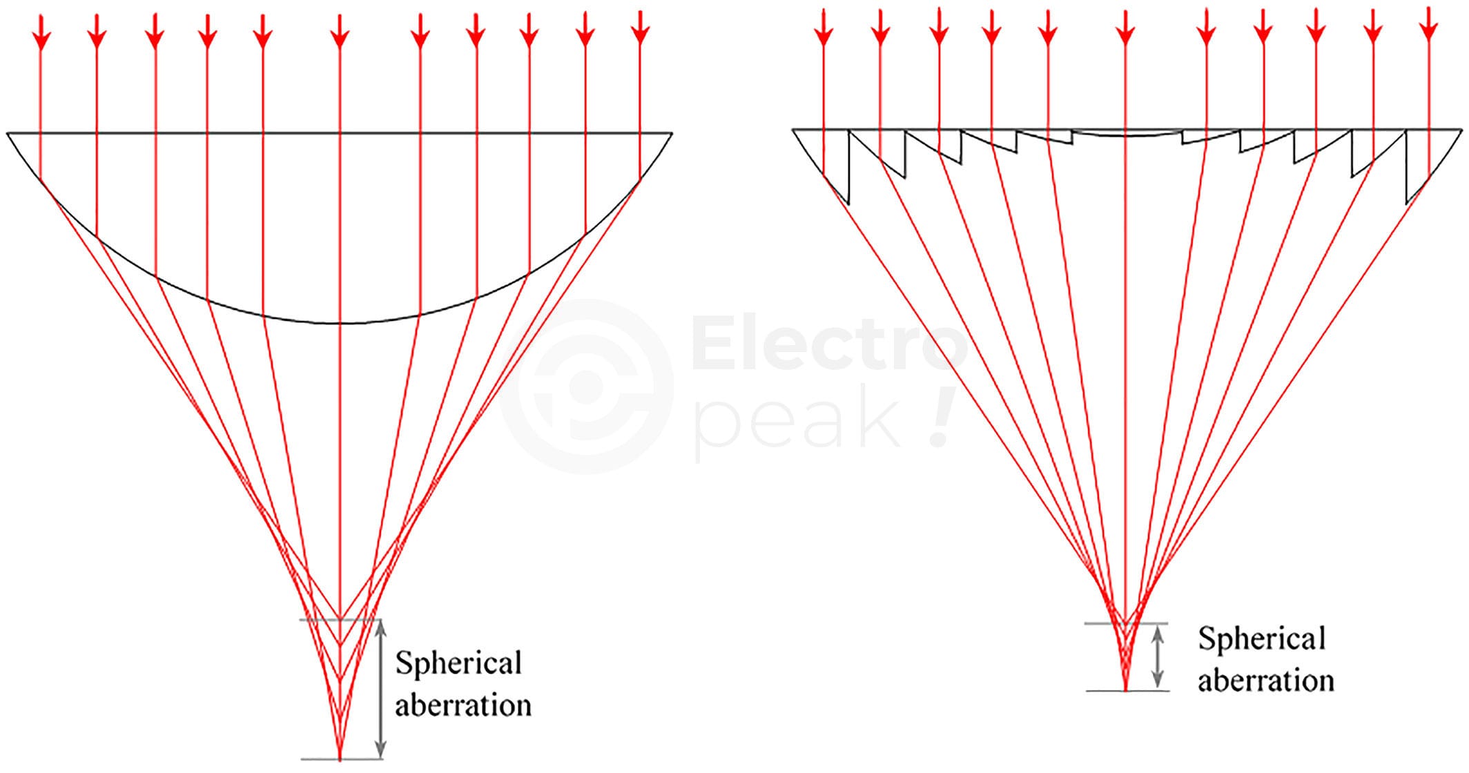
A Fresnel lens has a series of concentric grooves carved on the plastic. These grooves act as individual refracting surfaces and converge the parallel light beams into a focal point. Therefore, a Fresnel lens can focus light similarly to a typical optical lens, despite being smaller in size.
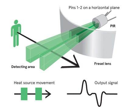
You can see how this lens works in the image below.
This lens increases the field of view of the pyroelectric sensor as shown below.

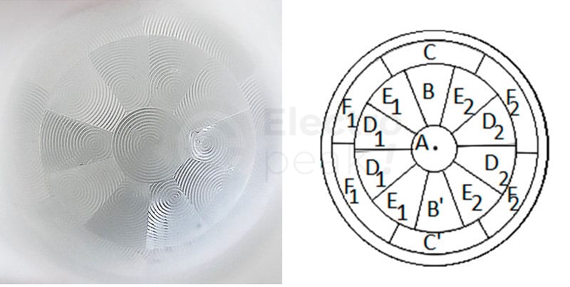
If you take a closer look at the Fresnel lens, you will notice that this sensor is divided into several parts, each with a Fresnel lens structure (image below).
According to what was mentioned, all available PIR modules use the same technology and method. Next, we will introduce one of the popular PIR modules.
Types of PIR modules
You can see the types of PIR modules in the image below.
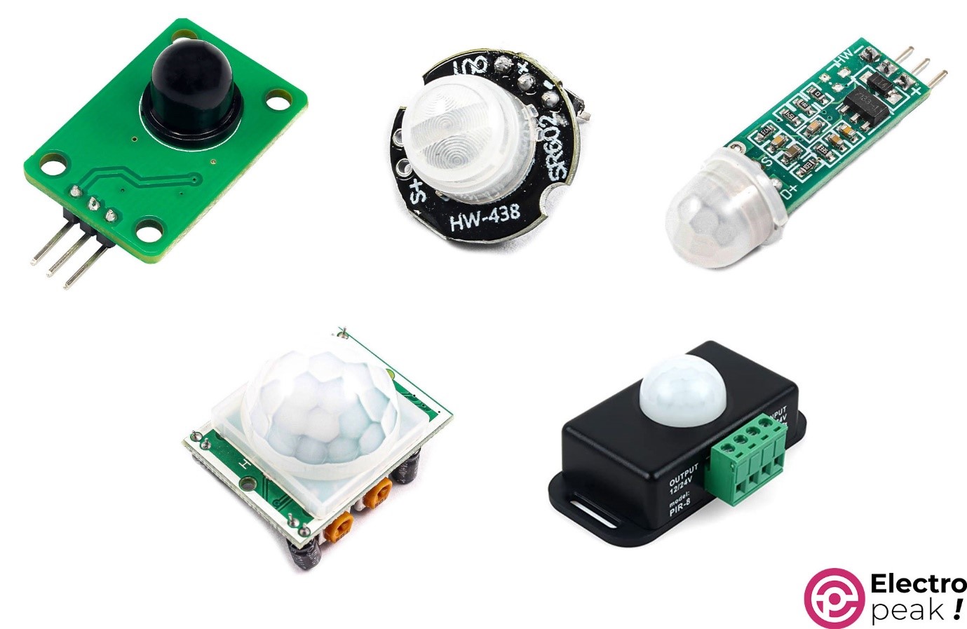
If we don’t consider the differences in dimensions, they all perform the same. The only difference between them is the pinout layout.
Their exact models, from top-left to right, are as follows. Click on each of them to read their detailed specifications.
- D203S PIR motion detection sensor module
- SR602 Infrared motion detection sensor module
- HC-SR505 Infrared motion detection sensor module
- HC-SR501 Infrared motion detection sensor module
- 5050 PIR motion detection sensor module (with a case)
They all have similar specifications; only two of them are slightly different. The HC-SR501 model has sensitivity and timer settings, and the 5050 model (with a case) supports 12-24V input and output.
The HC-SR501 model has more features and will be the one we focus on.
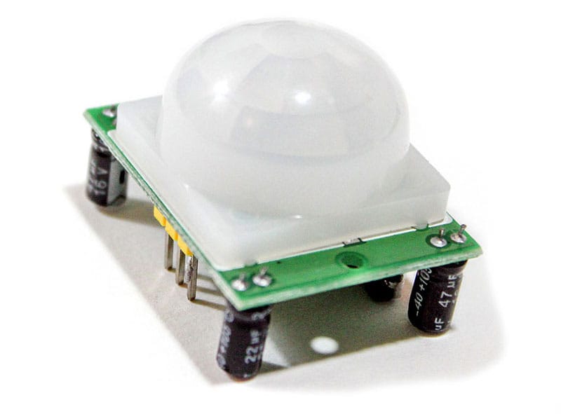
The HC-SR501 PIR Module
HC-SR501 is a popular and widely used passive infrared (PIR) sensor module known for its simplicity, affordability, and good motion detection. Its small size and physical design make it easy to use in your project.
It is pretty easy to work with the HC-SR501 module. It operates with a supply voltage range of 4.5 to 20 V, and generates a logical 1 output when motion is detected.
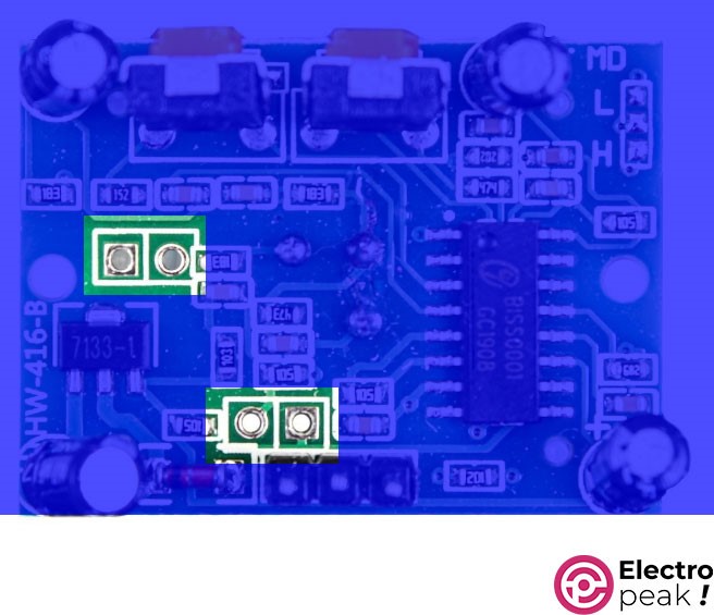
Here’s the schematic of a HC-SR501 module.
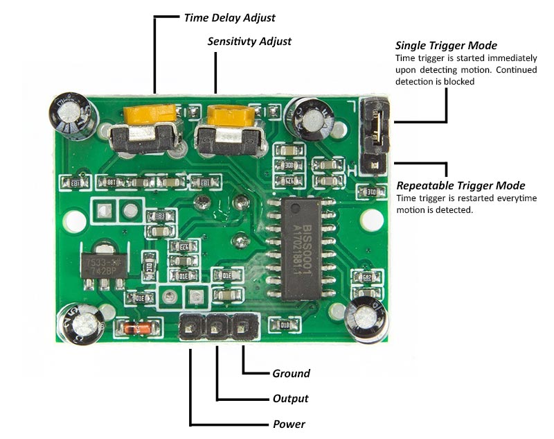
The Components of HC-SR501 PIR Module
As shown in the image above, the HC-SR501 module board has two potentiometers and a jumper that allow you to adjust the module. Let’s see what they do.
Delay and Sensitivity Potentiometers
The two potentiometers adjust the sensitivity and delay time after motion is detected. One of the potentiometers determines the maximum detection range, which can be adjusted from approximately 3 meters to 7 meters (9 to 21 feet), however, the room layout can affect the actual range. You can turn the potentiometer clockwise to increase the sensitivity, and vice versa.
The other potentiometer controls the delay time after the sensor is activated. This potentiometer determines how long the output remains HIGH after motion is detected, and it can be adjusted from 1 second to about 3 minutes. You can turn the potentiometer clockwise to increase the delay, and vice versa.
Trigger Mode Jumper
In addition to the potentiometers, there is a 2-mode jumper on the board that determines the output trigger mode.
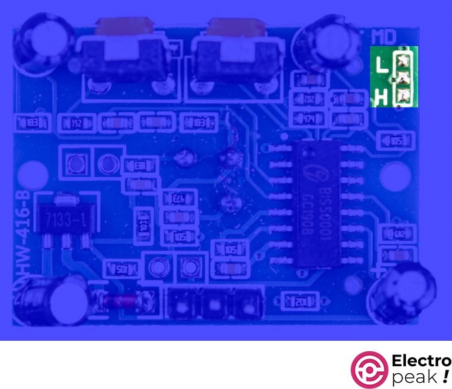
If the jumper is set to the L or Single trigger mode, the output will go HIGH as soon as motion is detected, and it will remain HIGH for a period determined by the potentiometer. During this time, no new motion will be detected. After the delay time passes and the output changes to LOW, if there is still motion in the environment, the output will go HIGH again immediately after detection by the sensor.
Look at the image below. In this case, the motion #3 is completely ignored.
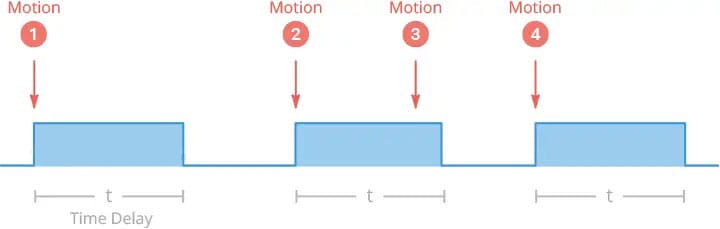
On the other hand, if you set the jumper to the H or Multiple trigger mode, the output will go HIGH as soon as motion is detected and will remain HIGH for a period determined by the potentiometer. Unlike the L mode, motion detection does not stop, and the time delay is reset each time a motion is detected. After detecting the last motion, the module output remains HIGH for the specified delay time and then immediately goes LOW.
Here’s how it works in the image below.

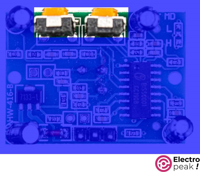
BISS0001 Processor
The module features a BISS0001 passive infrared controller IC. BISS0001 is one of the most stable PIR controllers available due to its noise immunity.
This chip takes the output from the pyroelectric sensor and performs minor processing on it to produce a digital output pulse.

HC-SR501 Module: Optional Components
The HC-SR501 module has soldered pads for two additional components, usually marked “RT” and “RL” on the board. You can solder optional components such as thermistor and LDR to these two parts. The description of each of them is as follows:
- RT: This is for the thermistor or temperature-sensitive resistor. You can add this component to HC-SR501 in order to use this PIR module at higher temperatures and increase the accuracy of the detector.
- RL: This is for the Light Dependent Resistor (LDR) or Photo Resistor. This component allows HC-SR501 to operate only in the dark. You can use this option to make a lighting system sensitive to ambient light.
These additional components can be soldered directly to the module or installed within a short distance using wires and connectors
Locked Out Time & Startup Delay in HC-SR501
When the sensor output goes LOW, the motion sensor is locked in this state for about 2 seconds.

For example, suppose you set the sensor delay to 4 seconds and the jumper to “L.” When you wave your hand in front of the sensor, the output will be HIGH for 4 seconds before going LOW. After that, the sensor won’t detect any motion for 2 seconds. As you can see in the image above, motion #2 is ignored here.
Startup Delay
Startup delay is typical of PIR sensors, and HC-SR501 is no exception, taking 30-60 seconds to start working. During this time, the sensor learns the infrared pattern of the surroundings and calibrates itself to identify motion.
During the delay, the sensor output may become HIGH by mistake, so it’s best to ignore motion. Also, when the sensor is being calibrated, there should not be too much movement in front of it as it may interfere with the process.
Now, let’s get it up and running.
Required Materials

Interfacing HC-SR501 PIR Sensor Module with Arduino and ESP32
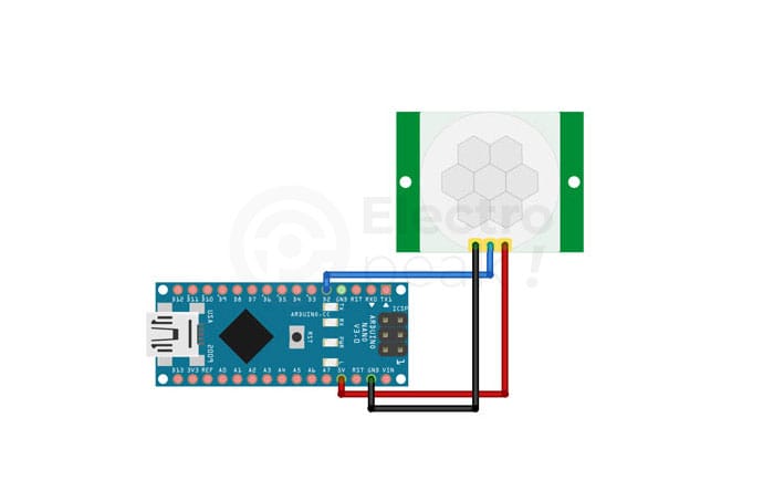
Step 1: Wiring
For Arduino boards, connect the module to an Arduino Nano as shown below.
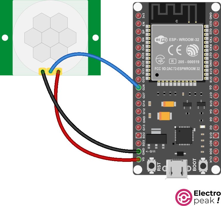
For ESP32/8266 boards, connect it to the PIR module as shown below.
Step 2: Code
Upload the following code to your Arduino board.
					/*
  by MajidMerati
   at https://electropeak.com/learn/
*/

#if defined(__AVR_ATmega328P__) || defined(__AVR_ATmega328PB__) ||defined(__AVR_ATmega2560__) || defined(__AVR_ATmega1280__)
const int PIR = 2;
#elif defined(ESP32)
const int PIR = 26;
#endif

const int LED = LED_BUILTIN;

bool PIRstate = 0;

void setup() {

  pinMode(PIR, INPUT);
  pinMode(LED, OUTPUT);
}

void loop() {

  PIRstate = digitalRead(PIR);

  if (PIRstate == HIGH) {
    // turn LED on:
    digitalWrite(LED, HIGH);
  } else {
    // turn LED off:
    digitalWrite(LED, LOW);
  }
}
After uploading the code, the LED on the board will light up when the sensor detects motion.
Using HC-SR501 PIR Sensor Module Independently
Connect the HC-SR501 PIR module to the 1-channel relay module as shown below.

In the circuit above, the device connected to the output of the relay module will turn on when the PIR sensor detects motion. Note that we have a DC motor here, but you can supply the voltage for the secondary side of the relay from the city power, and power all kinds of household or industrial appliances. The only change you need to make to the above circuit is to disconnect the positive (red) and negative (yellow) wires —connected to the secondary side (power section) of the relay module— from the output of the DC adapter jack and then connect them, respectively, to the load and neutral of the city power.
What’s Next?
In this tutorial, we learned about the structure and function of various PIR modules — the HC-SR501 PIR module, in particular.
These modules are widely used for various applications such as smart places and the Internet of Things (IoT).

Comment (1)
Choose very good search phrases and you can attract people
today.