
Product added to cart

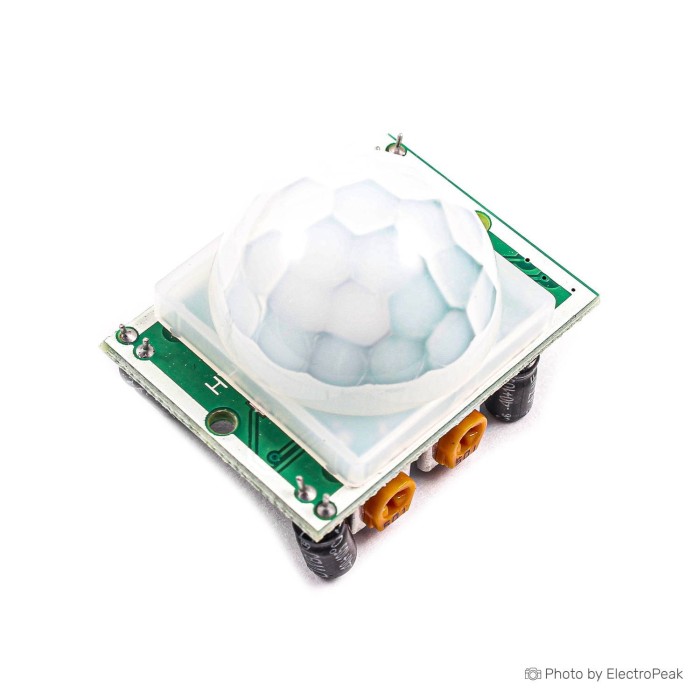
HC-SR501 PIR Motion Detection Sensor
$0.6900
In stock
SKU
SEN-05-005
Volume discounts:
- +50 4 % $0.6600
- +100 7 % $0.6400
- +300 9 % $0.6300
- +500 12 % $0.6100
- +1000 13 % $0.6000
Ships in 2-3 business days, then:
Free delivery in 12-15 days by Tracked Economic Shipping on orders over $100.
Free delivery in 7-10 days by Express Shipping on orders over $300.
More shipping info

Shop with confidence Learn More
 GP2Y0A21YK0F Infrared Distance Sensor Previous
HC-SR501 PIR Sensor Review: Motion Detection Basics
The HC-SR501 is a compact passive infrared (PIR) motion-detection module that detects human or object movement by sensing changes in environmental infrared radiation. It suits hobby electronics, Arduino-compatible systems, automation prototypes, and motion-activated lighting or security triggers. For maker setups, it offers adjustable 3 to 7 meter sensing with a standard TTL digital output. It is not intended for detecting stationary individuals, use in electrically or thermally unstable environments, or commercial production runs that require strict unit-to-unit consistency. Typical market pricing is around $2–3 USD, though current store pricing is not listed. For other sensing methods, browse our motion sensor category.
Specifications of HC-SR501 PIR Motion Detection Sensor
- Voltage: 5~20 V
- Current consumption: 65mA
- Standby current: 50uA
- TTL output: 0V – 3.3V
- Delay time: 0.3~5 min
- Lock time: 0.2 sec
- Trigger modes: L
- Trigger modes: H
- Storage temperature: -15 ~ 70 (⁰C)
- PCB size: 32*24mm
- Lens size: 23mm
- Distance between screws: 28mm
- Detection angle: 110 degrees
- Detection distance: 3 to 7 meters
HC-SR501 PIR sensor specifications explained
The HC-SR501 hardware parameters determine its electrical interface, enclosure dimensions, and detection-zone setup.
| Specification | Listed Value | Why it matters |
|---|---|---|
| Input Voltage | 5~20 V | Requires at least 5V to power the onboard regulator. Supplying only 3.3V falls outside stated operational limits. |
| Output Level | TTL output: 0V – 3.3V | Provides a discrete digital binary signal (LOW or HIGH), not a continuous analog reading. Directly safe for 3.3V logic inputs. |
| Detection Coverage | 3 to 7 meters, 110 degrees | Defines a conical detection area for room or doorway monitoring. Trimming sensitivity alters the outer boundary, not near-field exclusion. |
| Delay Time | 0.3~5 min | Controls how long the digital output remains HIGH after motion ceases. Adjusted via an onboard potentiometer. |
| Trigger Modes | L and H | Mode L uses single, non-repeatable triggering and resets after the delay. Mode H uses repeatable triggering, extending the HIGH output while motion persists. |
| Current & Standby | 65mA active / 50uA standby | The 50uA standby current suits idle monitoring, while the 65mA figure reflects maximum active circuit drive capacity. |
| Dimensions & Mounting | 32*24mm PCB, 23mm lens, 28mm screw spacing | Sets the enclosure cutout for the dome lens and the standoff-hole pattern for mounting brackets. |
For builds where low sleep current and a smaller footprint matter more than onboard trimmer adjustments, the SR602 PIR sensor module draws roughly 20µA in sleep mode. Its delay and sensitivity changes, however, require swapping surface-mount resistors.
HC-SR501 PIR sensor limitations and false triggers
PIR sensors do not detect movement through physical displacement. They respond to shifting thermal gradients across optical zones divided by the Fresnel lens. A person sitting motionless will therefore stop triggering the sensor once thermal equilibrium is reached. Passive infrared alone leaves gaps where continuous occupancy detection is required.
Environmental conditions can cause unexpected triggers. Direct sunlight sweeping across a room, radiator convection currents, air conditioning cycles, and high-frequency electromagnetic interference can produce spurious state changes. Glass windows block thermal infrared radiation, so movement outside will not be detected. Where enclosure concealment or barrier penetration is required, the HW-M10-A microwave motion sensor senses movement through glass, thin wood, or plastic using Doppler radar.
After power-up, the sensor enters an initial calibration window of 10 to 60 seconds. Keep the detection zone clear during this phase so it can establish a baseline. Many modules also have an approximate 2.5-second blocking period after an output pulse ends, during which new movement is not registered. Generic modules are manufactured across multiple production runs, so component quality, potentiometer ranges, and default jumper configs can vary. Standard modules are therefore practical for bench prototypes and hobby setups rather than mission-critical security hardware. For detailed installation guidance, review our complete PIR wiring and setup guide.
HC-SR501 PIR sensor compatibility and setup
The HC-SR501 uses three standard header pins: VCC, GND, and OUT. The module requires 5V to 20V on VCC, while its internal regulator sets the logic high level on OUT to 3.3V. The signal connects directly to 3.3V GPIO systems such as ESP32, ESP8266, and Raspberry Pi without logic level shifters. It also remains high enough to register as a reliable logic HIGH on standard 5V Arduino boards.
| Platform / Target | Supply Pin | Logic Level Compatibility | Interface Notes |
|---|---|---|---|
| Arduino 5V Boards | 5V Rail | 3.3V TTL out reads as HIGH | Connect to any standard digital GPIO pin. |
| ESP32 / ESP8266 | 5V / VIN Rail | Direct 3.3V GPIO match | Do not attempt to power VCC from the 3.3V rail. |
| Raspberry Pi | 5V Pin (Pin 2 or 4) | Direct 3.3V GPIO match | Share ground reference with the Pi GPIO bus. |
No dedicated libraries or software drivers are required to get started. Use this verification sequence to test module functionality:
- Connect VCC to 5V and GND to common ground using jumper wires for VCC, GND, and OUT connections.
- Connect the OUT pin to a digital input on your development board, or directly to a test circuit with a current-limiting resistor and an LED to ground.
- Apply power, then remain completely outside the detection area for 60 seconds to allow internal baseline calibration.
- Walk across the front of the lens. The OUT line will drive to 3.3V, lighting the LED or registering a digital HIGH in code.
- If the output stays HIGH continuously, check whether the delay potentiometer is set to its maximum position or the mode jumper is configured for continuous retriggering.
For firmware examples across microcontroller platforms, consult our full PIR sensor wiring guide and view an Arduino motion and gesture project example.
HC-SR501 PIR sensor projects and accessories
The HC-SR501's digital output suits home automation, security alerts, and educational projects:
- Motion-Activated Lighting: Trigger low-voltage LEDs or nightlights with adjustable delay cycles.
- Intrusion Alerts: Provide a digital trip signal to an ESP32 or ESP8266 for networked push notifications.
- Interactive Displays: Wake displays or ambient art installations when visitors approach.
- Automated Enclosures: Signal secondary door mechanisms or ventilation systems (inferred automation setups).
The OUT pin provides a low-current logic signal, so it cannot drive motors, solenoids, or mains-voltage relays directly. These devices require a transistor, MOSFET switch, or optocoupled relay module. For project implementations, review an active motion-controlled Arduino project.
Required Hardware
- A microcontroller or digital input circuit, such as an Arduino, ESP32, or Raspberry Pi.
- A stable DC power source within 5~20 V.
- Breadboard Jumper Wire Kit - 140 Pieces for wiring the 3-pin interface to your breadboard or controller.
Recommended Hardware
- A solderless breadboard for rapid circuit assembly.
- A test LED and 330-ohm resistor for bench verification.
- A switching transistor, MOSFET, or relay driver module for controlling external lighting, locks, or motors.
- A custom enclosure that shelters the PCB and allows for the 32*24mm board area and 28mm hole pattern.
Optional Accessories
Alternative Fresnel lenses can be used for specialized optical experimentation, but verify dimensional compatibility with the HC-SR501's standard 23mm dome before mounting:
- 8002 PIR Sensor Fresnel Lens - 20mm, White
- 8605-3 PIR Sensor Fresnel Lens - 34mm, White
- 8002 PIR Human Fresnel Lens - 8mm, White
HC-SR501 vs PIR motion sensor alternatives
The right motion or presence detector depends on power constraints, detection coverage, and whether the project must sense moving bodies or stationary occupants.
| Feature | HC-SR501 (PIR) | SR602 PIR Module | HLK-LD2410B Radar | Waveshare S3KM1110 |
|---|---|---|---|---|
| Technology | Passive Infrared | Passive Infrared | 24GHz FMCW Radar | 24GHz FMCW mmWave |
| Detection Type | Gross thermal motion | Gross thermal motion | Moving and stationary presence | Movement and micro-motion |
| Range | 3 to 7 meters | Up to ~5 meters | Configurable range gates | Up to 10m move / 6m micro |
| Supply Voltage | 5~20 V | 3.3V–15V | 5V nominal | 3.3V |
| Current Draw | 50uA standby / 65mA rating | ~20µA sleep | Active radar draw (~80mA) | 50mA average operating |
| Adjustments | Dual potentiometers + jumper | Soldered chip resistors | Bluetooth / Serial app | UART configuration |
Where line-of-sight thermal infrared does not suit the design, consider these RF Doppler radar alternatives:
- RCWL-0516 microwave radar sensor: Provides 360-degree detection up to 7 meters through light obstacles without an exposed lens.
- RCWL-0515 microwave motion sensor: Offers up to 12 meters of coverage and resists environmental fluctuations such as wind and thermal gradients.
- HW-M10-A microwave motion sensor: Detects motion through non-metallic enclosures including plastic or wood project boxes.
HC-SR501 PIR sensor FAQ
How far can the HC-SR501 detect motion?
The module is rated for a detection distance of 3 to 7 meters with a 110-degree field of view. The onboard sensitivity potentiometer adjusts the maximum range outward or inward rather than excluding nearby zones.
What do L and H trigger modes mean on the HC-SR501 PIR sensor?
Mode L is non-repeatable triggering: the output goes HIGH on motion, remains HIGH for the preset delay period, then turns LOW even if movement continues. Mode H is repeatable triggering and keeps the output HIGH while ongoing movement is detected in the area.
Why does the HC-SR501 PIR sensor trigger randomly after power-on?
The sensor needs an initial 10 to 60 second warm-up and calibration cycle to establish its infrared baseline. Movement in the detection area during this window, or placement near heaters, windows, and drafty vents, causes false trigger cycles.
Can I use the HC-SR501 with an ESP32 or Raspberry Pi?
Yes. The OUT pin provides a 3.3V TTL signal that connects safely to 3.3V GPIO inputs. The VCC pin still requires 5V or higher, so power it from the development board's 5V/VIN rail rather than the 3.3V supply.
Does the HC-SR501 output 5V when powered from 5V?
No. The module outputs 0V to 3.3V regardless of supply voltage. An onboard regulator sets the logic level, keeping the output safe for both 3.3V and 5V microcontrollers.
Can the HC-SR501 detect a person who is sitting still?
No. Passive infrared modules rely on changing thermal radiation across split optical elements. If a person stops moving, the sensor resets. For room occupancy sensing, the HLK-LD2410B 24GHz radar sensor is designed for stationary presence detection.
Is the HC-SR501 suitable for outdoor use?
The stock module has no ingress protection rating and is sensitive to rain, direct sunlight, wind gusts, and outdoor ambient temperature shifts. Use it indoors or in a sealed, weatherproof housing designed for infrared transmission.
Can I use the HC-SR501 for a battery-powered project?
It can operate on battery power if the supply remains between 5V and 20V to satisfy the onboard voltage regulator. For compact 3.3V battery circuits requiring sub-50µA draw, consider the SR602 PIR sensor module, which runs directly on 3.3V with ~20µA sleep draw.
Purchase decision summary
- Ideal for: Arduino, ESP32, and Raspberry Pi hobby projects; interactive installations; indoor automation lighting; benchtop prototyping; and general motion-activated circuits needing 3 to 7 meter detection.
- Maybe for: Battery-powered setups with access to a 5V+ rail, and basic occupancy lighting where coarse body movement is adequate to reset the timer.
- Consider another option if: You require detection of stationary occupants, need direct 3.3V-only operation without an external step-up, intend to install the unit outdoors unprotected, or require factory-calibrated unit-to-unit consistency for commercial products.
Buying checklist
- Verify that passive infrared motion detection suits your project rather than stationary presence sensing.
- Confirm your power rail can supply between 5V and 20V DC.
- Ensure your controller or circuit can read a 3.3V digital HIGH signal.
- Check that 3 to 7 meters of range and a 110-degree cone meet your room or doorway layout.
- Verify your physical enclosure allows for the 32*24mm PCB, 23mm diameter lens, and 28mm mounting hole spacing.
- Ensure the installation site is positioned away from direct sunlight, air vents, and heat sources.
- Have jumper wires on hand, along with a dedicated relay or transistor driver if you intend to switch high-current loads.
| Interface Type | Digital |
|---|---|
| Operating Voltage (V) | 5~20 V |
| Operating Current (mA) | 65mA |
| Operating Temp (°C) | -15 ~ 70 °C |
| Dimensions (mm) | PCB: 32*24mm, Lens: 23mm, Screw distance: 28mm |
| Mounting Type | Screw holes |
| Output Type | Digital |
| Response Time | 0.2 sec |
| Detection Distance | 3 to 7 meters |
| Detection Angle (°) | 110 degrees |
| Sensing Method | PIR (Passive IR) |
| Chipset | HC-SR501 |
| Channels | 1-channel |
| Sensor Model | HC-SR501 |
Write Your Own Review

Please complete your information below to login.
Sign In
Create New Account