
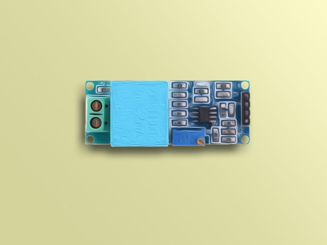
Discover the capabilities of the ZMPT101B voltage sensor and learn how to interface it with Arduino for precise AC voltage measurement. This voltage transformer module allows you to measure AC voltages up to 250 volts with analog output. As the input voltage changes, the output voltage of the sensor adjusts accordingly.
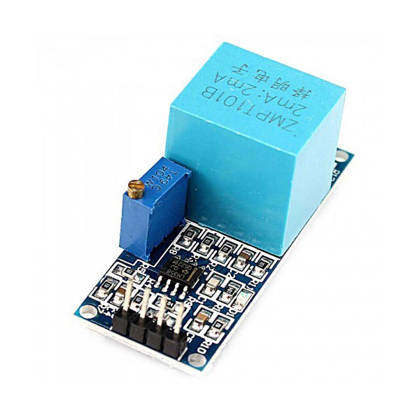
What is ZMPT101B Voltage Sensor?
Note
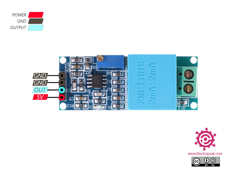
ZMPT101B Voltage Module Pinout
The ZMPT101B module has 4 pins:
- VCC: Module power supply: 5 V
- GND: Ground
- OUT: Module output which is analog.
You can see Pinout of ZMPT101B Voltage Module in the following image:
Required Materials
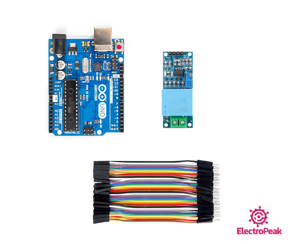
Hardware Components
Software Apps
Interfacing ZMPT101B Voltage Sensor with Arduino: Step-by-Step Guide
Step 1: Circuit
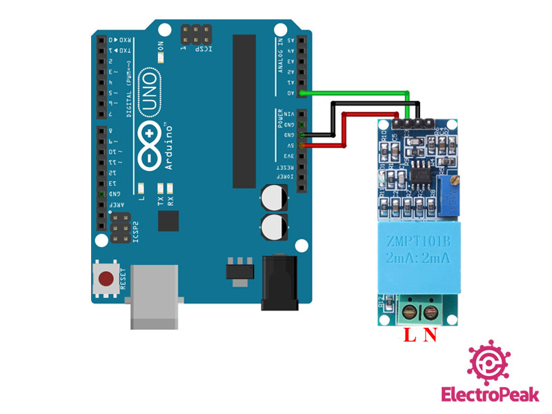
Connect the module to the Arduino according to the following image.
Warning
Step 2: Code 1
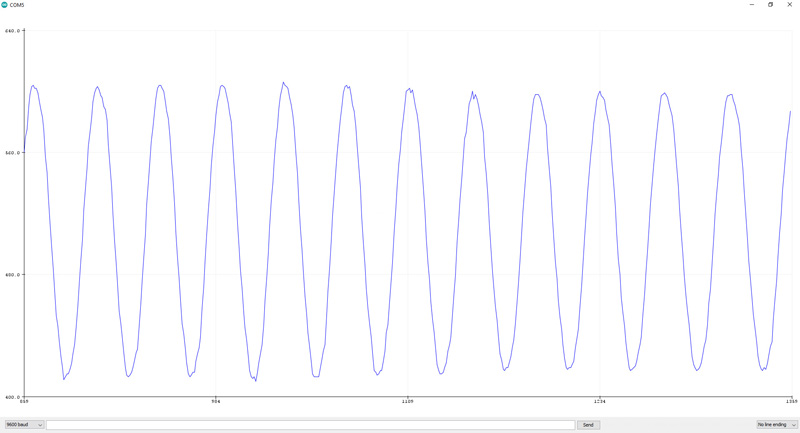
Upload the following code to your Arduino and then open the Serial plotter window from the Tools menu. If nothing is connected to the module inputs (module input is 0 volts), your diagram will show a number around 512 (i.e. 2.5 volts).
If you apply 220V AC to the input, you will see a voltage sinusoidal diagram on the Serial plotter.
/*
  ZMPT101B - AC Voltage sensor
  Show AC wava in serial plotter

  modified on 7 Sep 2020
  by Mohammad Reza Akbari @ Electropeak
  Home
*/


void setup() {
  // put your setup code here, to run once:
  Serial.begin(9600);
}

void loop() {
  Serial.println(analogRead(A0));

  delay(100);
Note
Make sure the sine wave is complete in the serial plotter, specifically the minimum and maximum parts of the chart. If your voltage pattern is not complete, you have to turn the potentiometer on the module to display the full waveform.
If the waveform is cut from the top or bottom, you will see an error in your measurement in the next step.
Step 3: Code 2
This module measures the peak-to-peak voltage. In this code, first it finds the maximum measured value (peak voltage) and then converts it to RMS value. You can see the result in the Serial Monitor.
/*
  ZMPT101B - AC Voltage sensor
  Calculate Voltage

  modified on 7 Sep 2020
  by Mohammad Reza Akbari @ Electropeak
  Home
*/

// Declare variables to store sensor values and results
double sensorValue1 = 0;
double sensorValue2 = 0;
int crosscount = 0;
int climb_flag = 0;
int val[100];   // Array to store sensor values
int max_v = 0;
double VmaxD = 0;  // Max voltage
double VeffD = 0;  // Effective voltage
double Veff = 0;   // Resulting voltage

// Setup function: Initializes the program
void setup() {
  Serial.begin(9600);  // Initialize serial communication at 9600 baud
}

// Loop function: Main program logic runs repeatedly
void loop() {
  // Read and process sensor values
  for (int i = 0; i < 100; i++) {
    sensorValue1 = analogRead(A0);  // Read analog sensor value from A0
    if (analogRead(A0) > 511) {
      val[i] = sensorValue1;  // Store sensor value in the array if it's greater than 511
    } else {
      val[i] = 0;  // Otherwise, set the value to 0
    }
    delay(1);  // Short delay for stability
  }

  // Find the maximum sensor value in the array
  max_v = 0;
  for (int i = 0; i < 100; i++) {
    if (val[i] > max_v) {
      max_v = val[i];  // Update max_v if a higher value is found
    }
    val[i] = 0;  // Reset the array element to 0
  }

  // Calculate effective voltage based on the maximum sensor value
  if (max_v != 0) {
    VmaxD = max_v;  // Set VmaxD to the maximum sensor value
    VeffD = VmaxD / sqrt(2);  // Calculate effective voltage (RMS) from VmaxD
    Veff = (((VeffD - 420.76) / -90.24) * -210.2) + 210.2;  // Apply calibration and scaling to Veff
  } else {
    Veff = 0;  // If no maximum value, set Veff to 0
  }

  // Print the calculated voltage to the serial monitor
  Serial.print("Voltage: ");
  Serial.println(Veff);

  VmaxD = 0;  // Reset VmaxD for the next iteration

  delay(100);  // Delay for 100 milliseconds before the next loop
}
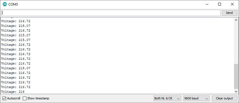
You can see the results for measuring city electricity voltage in the figure below.
In conclusion, by following the step-by-step guide and interfacing the ZMPT101B voltage sensor with Arduino, you can effortlessly achieve precise and reliable AC voltage measurement. This versatile module, with its analog output and wide measurement range of up to 250 volts, provides valuable insights into voltage patterns. Whether you’re monitoring city electricity voltage or working on other AC voltage measurement projects, the ZMPT101B voltage sensor, combined with Arduino, offers an accessible and accurate solution. Unlock the potential of your projects with this powerful combination of technology.
Remember to implement proper safety precautions when dealing with high input voltages. For more detailed instructions, additional resources, and information on other Arduino-related topics, visit Electropeak website.

Comments (52)
how the following formula is derived>?can you please explain?
Veff = (((VeffD – 420.76) / -90.24) * -210.2) + 210.2;
Hello.
It’s actually a formula to calculate the input voltage RMS by using the maximum value of the sensor output voltage. And here’s how it’s derived: The graph of the sensor output voltage when it has the city electricity as its input is given as the result of the first code. You can see that the maximum voltage is somewhere around 600. And we already know that the input voltage RMS is 220V. First, the peak value of the sensor output voltage is divided by sqrt(2). -Since it is needed for calculating the RMS- Then the rest is just a linear transformation to get an output around 220 from the sensor output voltage.
As salam alaikm dear
Fayyaz Hussain Here
I want to ask that what is the output of Module in form of DC voltages or AC if any one then what is the Mini and Max value of the Module for Arduino to formulate and display On LCD
like
220 AC voltage vs Module output voltage
Thanks
Hi. As you can see in the article, the image of the output of this module is provided -right above the “step 3” section-. And you can see that the output is actually an AC voltage. In order to calculate the input AC Voltage, you need to find the maximum of the output -Vmax_v- and use the formula given in the second code -“step 3” section-.
Hello
Can you please explain the linear formula you have given. I didnt understand your explanation on that in the commwnt section as well.
Thanks.
I wont to ask you for using zmpt101b for mesuring up to 400v
Hi,
As you can see in the first section of the tutorial, the ZMP101b module can only measure AC voltages up to 250 volts. So, I’m afraid it’s not suitable for your application.
Hi,
I have a question about analog output. The value for out put is sth between 0-5 V. in this situation if I connect the module to 120V and 230V, what we will be the value of output?
Thank you.
Hi,
As you said, the output will be between 0 and 5 volts, but I can’t say the exact value. You need to test that yourself.
can i use this code with esp32?? if i cannt so what is the suitble code can i use?
Yes, you can use almost the same code for ESP32. All you need to change is to replace “A0” in line 28 and 29 with any of the pins of ESP32. Also make sure you connect the output of the sensor to that particular pin.
is there any change in the code for standard 120v
Hi.
Yes, you actually need to rewrite most of the formulas. First, you should use code 1 to get the maximum of the output voltage of the sensor. Then, you need to derive a formula between that maximum value and the RMS of the input voltage and use it in code 2.
How would you derive a formula please and thank you
Hi,
It is already answered in the previous comments. This one might be good for you: “This is how it’s derived: The graph of the sensor output voltage when it has the city electricity as its input is given as the result of the first code. You can see that the maximum voltage is somewhere around 600. And we already know that the input voltage RMS is 220V. First, the peak value of the sensor output voltage is divided by sqrt(2). -Since it is needed for calculating the RMS- Then the rest is just a linear transformation to get an output around 220 from the sensor output voltage.”
You can do the same process for standard 120V.
Hello, nice tutorial I tried your code and it’s Woking very well. What is the cause that the sensor can’t measure more than 250v? In the datasheet of zmpt101b transformer, it says it can measure upto 1000v.
Hi.. Can you please explain more about how to derive each value of the equation.. [Veff = (((VeffD – 420.76) / -90.24) * -210.2) + 210.2]. I’m try to implement 3 phase voltage meter using esp32.. I also note that the value you get as 511 is different when we consider esp32 since its ADC is 4096.. It would be highly appreciate, if you can give me a hand.. Thanks
Hi,
The question you’re asking is almost the same as an older comment. So, I give you the same answer.
“It’s actually a formula to calculate the input voltage RMS by using the maximum value of the sensor output voltage. And here’s how it’s derived: The graph of the sensor output voltage when it has the city electricity as its input is given as the result of the first code. You can see that the maximum voltage is somewhere around 600. And we already know that the input voltage RMS is 220V. First, the peak value of the sensor output voltage is divided by sqrt(2). -Since it is needed for calculating the RMS- Then the rest is just a linear transformation to get an output around 220 from the sensor output voltage.” Ask me if you need any further information. And about ESP32, you need to replace 511 with 2050. Also, remember that ESP32 is a 3.3V microcontroller and 4096 means 3.3V.
Hello!
I have a 120V 60Hz power network.
I cannot adjust the potentiometer, even after 1 hora spinning for both directions. The wave form doesn’t change at all.
Would you have any tip to help me?
Thank you!
Hi,
The potentiometer on this module is multi-turn. So, you probably need to turn it more to see a difference in the output wave form.
what would i change to measure 2 volts ?
Hi.
As you can see in the article, this module is designed to measure high voltages up to 250V. So. you can’t use it to measure 2 volts. Actually, to measure 2 volts, you don’t need to use any module. You can directly connect that wire to any of the analog pins of your Arduino board and use the “analogRead()” function to measure the voltage.
Hello.
I use 2 moduls ZMPT to measure AC voltage, can you help me to explain more about using this moduls in one project?
thank you for being willing to help
Hi.
What exactly is your problem? There is no significant difference between interfacing one ZMPT101B module and two ZMPT101B modules with Arduino. You just need to use two analog pins to read the output of your modules.
Does it also calculate Current???
Hi.
Actually, no, it can only measure AC voltage. For measuring current, you can use the following tutorials:
https://electropeak.com/learn/interfacing-acs712-current-module-with-arduino/
https://electropeak.com/learn/interfacing-ina219-current-sensor-module-with-arduino/
https://electropeak.com/learn/interfacing-zmct103c-5a-ac-current-transformer-module-with-arduino/
Hi! I am working whit this module and a ESP32. I already read the above comments, but i do not understand the changes that i have to make in this line: Veff = (((VeffD – 420.76) / -90.24) * -210.2) + 210.2;
Where did the conversion for the 12 bits work for the ESP32? I also change the 511 for the 2050 that i read in the answers.
Thank you!
Can the analog output be used to determine frequency and count cycles to detect a cycle drop or glitch ?
Hi dear
yes it can. you need a zero crossing unit to estimate every period of wave for frecuency measurment.
just read analog measurment when signal is equal to zero.
Hi
Can You please help me how I can use this conversion with raspberry Pi 3 .
Please suggest how should I calibrate the analog value using raspberry Pi 3?
Hi
I am getting strange results, when there is no 650V mains, when there is 830V mains. Where did the error occur?
Hi dear
this module is used for AC Voltage
Are your sure about the AC/DC Voltage?
Please note that the maximum measurable range of this module is 250VAC
Hello.
I want to measure energy consumption without using the software, only to be displayed on the LCD, is it Possible?
Hi.
you can use any commerial plug in Socket power Meter
like below
https://www.amazon.com/Suraielec-Calculator-Protection-Electricity-Electrical/dp/B08GSPLZBN
Bonjour,
Je suis confronté à une situation complexe : je souhaite mesurer la tension et le courant d’un groupe électrogène de 650 kVA qui est triphasé. Chacune des phases fournit une tension de 220 V et est composée de 400 V. Mon problème est que l’électrogène fournit un courant total de 1083 A, oui A et non mA. Je me demande donc si en insérant un capteur dans une seule phase qui fournit 220 V et 1083 A, le capteur sera en mesure de supporter cette charge ou s’il sera endommagé instantanément. Toute aide sera la bienvenue, car je suis actuellement bloqué.
Par ailleurs, si vous avez des suggestions pour un capteur qui pourrait être utile pour mesurer la tension et le courant dans cette situation, je serais ravi de les entendre.
Merci d’avance pour votre aide.
Hello,
I am facing a complex situation: I need to measure the voltage and current of a 650 kVA three-phase generator. Each phase provides a voltage of 220 V and is composed of 400 V. My problem is that the generator supplies a total current of 1083 A, yes A and not mA. I wonder if by inserting a sensor into a single phase that provides 220 V and 1083 A, the sensor will be able to handle this load or if it will be damaged instantly. Any help would be welcome, as I am currently stuck.
Also, if you have any suggestions for a sensor that could be useful for measuring voltage and current in this situation, I would be delighted to hear them.
Thank you in advance for your help.
I have a doubt that I have to test 220V which can go beyond 220V as we have to change the frequency…
so the output will be a DC. Can you tell me what will the output and formula for doing the same.
You can apply up to 250V.
But I didn’t understand what you meant about changing the frequency. Could you explain a little more?
Hello, I have a question. I want to make a comparation to evaluate if the Veff variable is bigger or smaller than 210 volts. And with that value make another variable change between HIGH and LOW. It funks well when its supposed to be HIGH, but my problem is that the variable is changing everytime when its supposed to be LOW. Is it possible to solve it by software?
Thank you, Here’s the code with my modifications:
#include
#include
int LedPin=13;
double ref=0;
double sensorValue1 = 0;
double sensorValue2 = 0;
int crosscount = 0;
int climb_flag = 0;
int val[100];
int max_v = 0;
double VmaxD = 0;
double VeffD = 0;
double Veff = 0;
void setup() {
Serial.begin(9600);
pinMode(LedPin, OUTPUT);
cli(); //desabilitar int globales.
TCCR1A=0;
TCCR1B=0;
OCR1A=50000;
TCCR1B |= (1<<WGM12);
TCCR1B |=(1<<CS10);
TCCR1B |=(1<<CS11);
TCCR1B |=(0<<CS12);
TIMSK1 |=(1<<OCIE1A);
sei();
}
void loop() {
for ( int i = 0; i 511) {
val[i] = sensorValue1;
}
else {
val[i] = 0;
}
delay(1);
}
max_v = 0;
for ( int i = 0; i max_v )
{
max_v = val[i];
}
val[i] = 0;
}
if (max_v != 0) {
VmaxD = max_v;
VeffD = VmaxD / sqrt(2);
Veff = (((VeffD – 420.76) / -90.24) * -210.2) + 210.2;
}
else {
Veff = 0;
}
Serial.print(“Voltage: “);
Serial.println(Veff);
VmaxD = 0;
ref = 210;
delay(100);
}
ISR(TIMER1_COMPA_vect){
if(digitalRead(Veff)<digitalRead(ref)){
digitalWrite(LedPin, LOW);
}
else{
digitalWrite(LedPin, HIGH);
}
}
I tested your code. It had some major problems. As you can see in the article, there are two examples. you can use the second example as a reference and change it to something as follows.
/*

  ZMPT101B - AC Voltage sensor

  Calculate Voltage
modified on 7 Sep 2020
by Mohammad Reza Akbari @ Electropeak
Home
*/
double sensorValue1 = 0;
double sensorValue2 = 0;
int crosscount = 0;
int climb_flag = 0;
int val[100];
int max_v = 0;
double VmaxD = 0;
double VeffD = 0;
double Veff = 0;
bool state = LOW;
void setup() {
Serial.begin(9600);
}
void loop() {
for ( int i = 0; i < 100; i++ ) { sensorValue1 = analogRead(A0); if (analogRead(A0) > 511) {
val[i] = sensorValue1;
}
else {
val[i] = 0;
}
delay(1);
}
max_v = 0;
for ( int i = 0; i < 100; i++ ) { if ( val[i] > max_v )
{
max_v = val[i];
}
val[i] = 0;
}
if (max_v != 0) {
VmaxD = max_v;
VeffD = VmaxD / sqrt(2);
Veff = (((VeffD - 420.76) / -90.24) * -210.2) + 210.2;
}
else {
Veff = 0;
}
if (Veff >= 210) {
state = HIGH;
} else {
state = LOW;
}
Serial.print("Voltage: ");
Serial.print(Veff);
Serial.print("\tstate: ");
Serial.println(state);
VmaxD = 0;
delay(100);
}
What is the lowest AC voltage this module will read?
Hi James
According to datasheet, you can adjust the measurement range by a resistor. Please refer to the datasheet to calculate the resistor value according to your desired measurement range.
Op
Where do the values 420.76, 90.24, and 210.2 come from?
In the above formula of Veff, you haven’t exactly specified, which of the values are considered for what….Can anybody tell me, so that I can properly apply the scaling and calibration factors, also I am using this module with stm32F411RE board, so what changes should I do with this code
Hello Every One,
i am Working on this module with stm32f103 series MCU so it has 3.3 adc 12bit(4096).
what will be the changes in above formula?
ac ranges from 110v to 250v
Hi Smit,
When reading the input value, make sure to divide it by 4 to bring it within the 0-1024 range for the code to function properly:
sensorValue1 = analogRead(A0)/4;Bonjour
Je viens de lire votre programme de mesure AC avec le module ZMPT101
Pouvez-vous m’expliquer les nombres choisis dans votre formule
Veff = (((VeffD – 420.76) / -90.24) * -210.2) + 210.2; // Apply calibration and scaling to Veff
merci d’avance
Please refer to the other comments where we have provided detailed explanations.
I would make the output of the LM358 TTL (0-5v) at the zero crossing. can we mod the circuit for this purpose?
Hello David,
The LM358 on this board operates in boost mode, and you can use it at the module’s output.
If you’re trying to design a zero-crossing circuit for a Triac, I recommend using this alternative circuit:
Connect two resistors (56kΩ tested) to the input of a PC814A optocoupler from the AC line. On the output side of the PC814A, you will receive a pulse at the zero-crossing point. To enhance the signal, you can add an LM358 at the output.