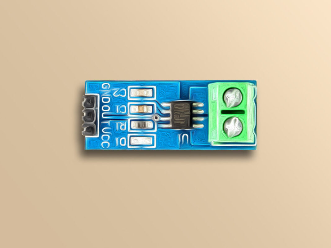
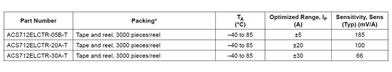
ACS712 chip is used to measuer DC/AC current based on the Hall effect. This chip is produced in 3 models with different maximum currents. Different models and output sensitivity of each model are shown in the table below:
Sensor sensitivity means that, for example, if you use 5 amp model, as input current increase 1 amp, the output voltage of the sensor increases about 185 mV.
Note
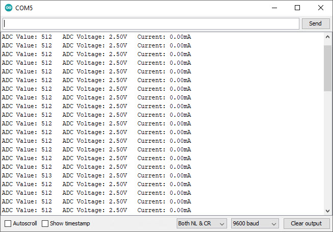
When input is not connected to something and there is no load on output, the sensor has an initial voltage (Offset) of Vcc/2. That is, if nothing is connected to the input and the supply voltage of the module is 5 volts, the output of the module will be 2.5 volts. As a result, the relationship between the output voltage of the sensor with 5 amp and the supply voltage of 5 volts is as follows:
Hi,
As you can see in line 23 of the code, a “for loop” has been used to get the output of the sensor. The output of the sensor has been obtained for “averageValue = 500” times, so it needs to be divided to “averageValue”. Actually, instead of getting a single sample of the output, we have gotten 500 samples of it and calculated their average to get rid of the noise that the output of the sensor might have. And about “voltage = sensorValue * 5.0 / 1024.0;”, sensorValue is actually the value we have read from the analog pin A0. That value is between 0 (equivalent to 0 Volts) and 1024 (equivalent to 5 Volts). So, that equation is used to get the output voltage of the sensor. And about “current = (voltage – 2.5) / 0.185;”, that is the formula between the current and the voltage of the sensor. It has already been mentioned in the article, in the “Note” in “ACS712 Current Module Features” section.
Hi.
The ACS712 current module has a single analog output. So, you can use as many of them as you want with an ESP32 board, as long as you have GPIO pins left. And for the coding, it’s not much different from the code written in this article. You just need to define all variables of the original code twice. For example, you can define sensorValue1, sensorValue2, voltage1, voltage2, current1, current2 and so on.
Does a “conditioning circuit” between the sensor and Arduino need to be used
to read an AC current signal? Or is there something code wise that can adapt
to an AC input instead of DC?
Hi dear
about the formula you right, it should be corrected.
but about the sensorValue Variable , it rewrite any time by new value and it is not a constant type.
so no need to reset to zero.
Well done on your article about connecting ASC712 to Arduino.
I have a 100/5 current transformer (5 amp output) I would like to connect and have read by the Arduino (UNO). I shunt across it with a 1-ohm resistor getting a 5-amp maximum output. Can I connect the output to the inputs of the ASC712 or just go directly into A0 of the UNO board?
Hi Larry
A question: What do you mean by input and output?
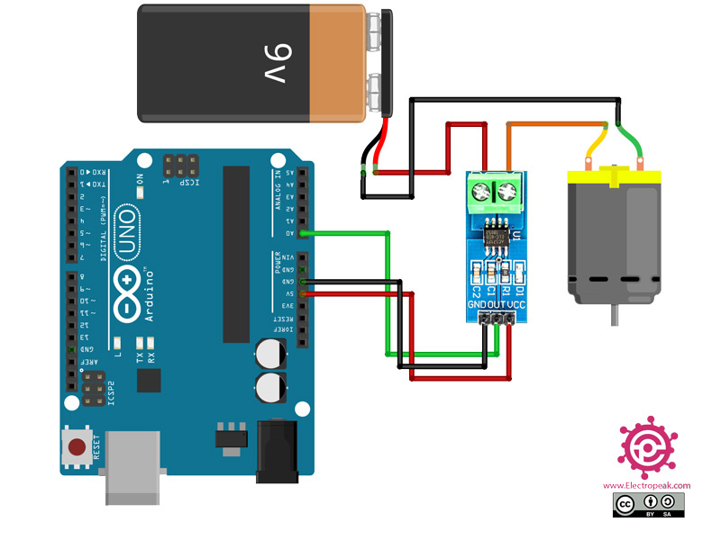
To use ASC712, you should connect it to the transformer output in series, and the module to the UNO.
I updated the interface circuit so you can understand it better


Comments (14)
Can you explain these to me:
sensorValue = sensorValue / averageValue;
voltage = sensorValue * 5.0 / 1024.0;
current = (voltage – 2.5) / 0.185;
Hi,
As you can see in line 23 of the code, a “for loop” has been used to get the output of the sensor. The output of the sensor has been obtained for “averageValue = 500” times, so it needs to be divided to “averageValue”. Actually, instead of getting a single sample of the output, we have gotten 500 samples of it and calculated their average to get rid of the noise that the output of the sensor might have. And about “voltage = sensorValue * 5.0 / 1024.0;”, sensorValue is actually the value we have read from the analog pin A0. That value is between 0 (equivalent to 0 Volts) and 1024 (equivalent to 5 Volts). So, that equation is used to get the output voltage of the sensor. And about “current = (voltage – 2.5) / 0.185;”, that is the formula between the current and the voltage of the sensor. It has already been mentioned in the article, in the “Note” in “ACS712 Current Module Features” section.
Hi can i ask you how to use acs712 sensor current with esp32 can u give the codeing
Hi.
The ACS712 current module has a single analog output. So, you can use as many of them as you want with an ESP32 board, as long as you have GPIO pins left. And for the coding, it’s not much different from the code written in this article. You just need to define all variables of the original code twice. For example, you can define sensorValue1, sensorValue2, voltage1, voltage2, current1, current2 and so on.
Hi,
I need the data on Website (IOT). request you to guide on the same. I have ESP32
Hi,
See if the following tutorial can help you.
https://electropeak.com/learn/speak-to-arduino-control-all-parts-by-google-assistant/
Does a “conditioning circuit” between the sensor and Arduino need to be used
to read an AC current signal? Or is there something code wise that can adapt
to an AC input instead of DC?
Hi Dear
no need any conditioning Circuit. you can use it for both AD/DC Measurment.
In the note a little before the link to the datasheet, shouldn’t your formula be Vout = 2.5 + 0.185*Iin?
In the code, shouldn’t sensorValue be reset to zero before each time the for loop is run?
Hi dear
about the formula you right, it should be corrected.
but about the sensorValue Variable , it rewrite any time by new value and it is not a constant type.
so no need to reset to zero.
how do I know if there is 1 amp bar on the module. I mean where the current came?
Hi,
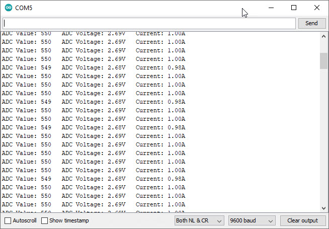
you can print and display output data in serial monitor on Arduino Board.
Well done on your article about connecting ASC712 to Arduino.
I have a 100/5 current transformer (5 amp output) I would like to connect and have read by the Arduino (UNO). I shunt across it with a 1-ohm resistor getting a 5-amp maximum output. Can I connect the output to the inputs of the ASC712 or just go directly into A0 of the UNO board?
Hi Larry
A question: What do you mean by input and output?
To use ASC712, you should connect it to the transformer output in series, and the module to the UNO.
I updated the interface circuit so you can understand it better