
Overview
Have you ever been sitting in your room, and want to turn things like light bulbs or fans on and off, but you don’t feel like doing it? Or you want to turn the cooling system on before arriving home, so it would be pleasantly cool by the time you’ve arrived?
So, if you like controlling electrical devices of your home remotely through your cell phone, this tutorial can be so useful for you.
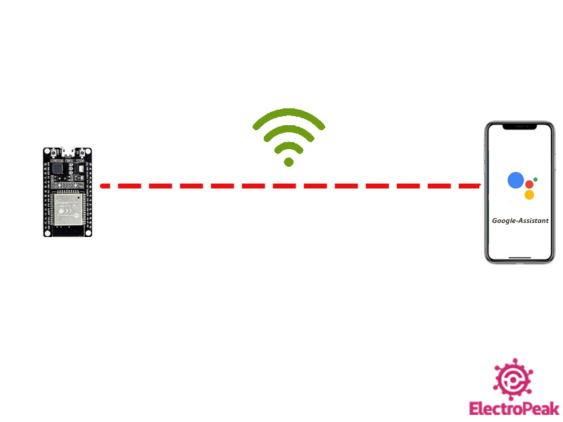
There is an application called “Google Assistant” installed on most smartphones. You can use Google Assistant to speak to your phone and send voice commands to it. Now, imagine your phone is connected to a microcontroller like Arduino or ESP32 via internet. Then, you’ll be able to speak to the microcontroller and send your voice commands for controlling electrical devices. You can use a relay module to connect the microcontroller to various electrical devices of your house such as light bulbs, fans, cooling system and so on and control them remotely.
What You Will Learn
As stated in the previous section, the goal of this tutorial is to learn how you can remotely control your electrical appliances. In this tutorial, we will be using an ESP32 board as our microcontroller. Having WiFi is one of its most important advantages.
To establish the connection, you can’t just connect the Google Assistant to the microcontroller directly. We need to use two interfaces to establish the connection between the Google Assistant and the ESP32. One for connecting to the Google Assistant and the other for connecting to the ESP32.
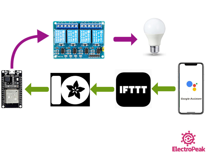
We use the IFTTT platform to communicate with Google Assistant. And since the IFTTT platform can’t be directly connected to the ESP32, we use another interface called Adafruit-IO to establish a communication between the IFTTT and ESP32.
In this tutorial, we first need to register in the “Adafruit-IO” website and build a block for controlling an LED. Then, using the Arduino IDE, we upload a code on our ESP32 for communicating with the Adafruit-IO. Next, we connect an LED to the ESP32 using a relay module. In the following, we need to create an account in the “IFTTT” website to set up the communication between the Google Assistant and Adafruit-IO.
Finally, we control the LED with some predefined voice commands. The steps explained in this article can be repeated for controlling different microcontrollers or different electrical devices.
What Is Adafruit-IO?
Adafruit-IO is actually a cloud storage space that you can connect to through internet. You can use it to connect to a microcontroller like an ESP32 and control its pins. You can actually use it to communicate with any microcontroller in an internet cloud space.
What Can Be Done Using the Adafruit-IO?
- Online display of data
- Make projects that need to be connected to internet
- Connect your project to other devices that are connected to internet
- Connect projects to web services

What Is Google Assistant?
Google Assistant is an AI assistant developed by google that is mainly available in almost all smart devices. Unlike the previous version, the new version of the Google Assistant can participate in two-way conversations. It can recognize words better than any other device and respond to your commands quickly.
The users can communicate with the Google Assistant with their natural voice, although it also supports the keyboard. Like the Google Now, the Google Assistant can search the internet, schedule events, change the hardware setting of your device, show data from Google account and so on. Google has also announced that the Google Assistant is able to detect objects and collect information about them through the camera. It also supports buying, sending money and identifying songs.

What Is IFTTT?
IFTTT is short for “If This, Then That”. It is a software platform in which different applications, devices and services can be connected to each other to create one or several automations. In fact, the IFTTT acts as a communication interface between them.
This automation is done through Applets. In other words, several programs are connected to each other to perform automated tasks. You can activate or deactivate these Applets in “IFTTT.com” website. You can either make your own Applets or use different Applets already available on the website.
In the next parts of the tutorial, you will learn how to work with the IFTTT website and make a new Applet.

Required Material
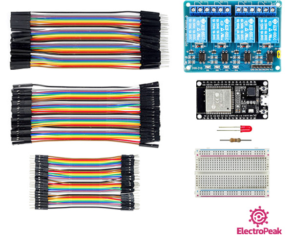
To continue with the tutorial, you need the following components:
Hardware Components
Software Apps
Step 1: Establish Connection Between ESP32 & Adafruit
As already mentioned, we need to use a platform called Adafruit-IO to connect the ESP32 to IFTTT. In this step, we are going to connect the ESP32 to Adafruit-IO.
The Code to Connect ESP32 to Adafruit-IO
First, we write the code we need. There are also some variables in the code we will set in the next steps.
Go to Sketch → Include Library → Manage Libraries. Search for “Adafruit MQTT” and install it like the following image.

The code below is taken from “Github” website. Copy and paste it on your Arduino IDE.
/*
  Made on 6 July 2021
  By Amirmohammad Shojaei
  Home
  based on “ajaynikam2410” Example
*/

//for esp32 use <wifi.h>, for esp8266 use <esp8266wifi.h>
// this code is for esp32 for using esp8266 you just need to change <wifi.h> into <esp8266wifi.h> and also change the relay pin
#include <WiFi.h>
#include "Adafruit_MQTT.h"
#include "Adafruit_MQTT_Client.h"


/************************* Pin Definition *********************************/

//Relays for switching appliances
#define Relay1            12
#define Relay2            13
#define Relay3            14
#define Relay4            27
#define buzzer            26

//buzzer to know the status of MQTT connections and can be used for any other purpose according to your project need.


/************************* WiFi Access Point *********************************/

#define WLAN_SSID       "wLAN_SSID"
#define WLAN_PASS       "wLAN_PASS"

/************************* Adafruit.io Setup *********************************/

#define AIO_SERVER      "io.adafruit.com"
#define AIO_SERVERPORT  1883                   // use 8883 for SSL
#define AIO_USERNAME    "AIO_USERUSERNAME"
#define AIO_KEY         "AIO_KEY"

/************ Global State (you don't need to change this!) ******************/

// Create an ESP8266 WiFiClient class to connect to the MQTT server.
WiFiClient client;
// or... use WiFiFlientSecure for SSL
//WiFiClientSecure client;

// Setup the MQTT client class by passing in the WiFi client and MQTT server and login details.
Adafruit_MQTT_Client mqtt(&client, AIO_SERVER, AIO_SERVERPORT, AIO_USERNAME, AIO_KEY);

/****************************** Feeds ***************************************/

// Notice MQTT paths for AIO follow the form: <username>/feeds/<feedname>

Adafruit_MQTT_Publish Light = Adafruit_MQTT_Publish(&mqtt, AIO_USERNAME "/feeds/light");


// Setup a feed called 'onoff' for subscribing to changes.
Adafruit_MQTT_Subscribe Light1 = Adafruit_MQTT_Subscribe(&mqtt, AIO_USERNAME "/feeds/led");
Adafruit_MQTT_Subscribe Fan1 = Adafruit_MQTT_Subscribe(&mqtt, AIO_USERNAME "/feeds/relay2");
Adafruit_MQTT_Subscribe Light2 = Adafruit_MQTT_Subscribe(&mqtt, AIO_USERNAME "/feeds/relay3");
Adafruit_MQTT_Subscribe Fan2 = Adafruit_MQTT_Subscribe(&mqtt, AIO_USERNAME "/feeds/relay4");


/*************************** Sketch Code ************************************/

// Bug workaround for Arduino 1.6.6, it seems to need a function declaration
// for some reason (only affects ESP8266, likely an arduino-builder bug).
void MQTT_connect();

void setup() {
  Serial.begin(115200);

  delay(10);

  pinMode(Relay1, OUTPUT);
  pinMode(Relay2, OUTPUT);
  pinMode(Relay3, OUTPUT);
  pinMode(Relay4, OUTPUT);


  Serial.println(F("Adafruit MQTT demo"));

  // Connect to WiFi access point.
  Serial.println(); Serial.println();
  Serial.print("Connecting to ");
  Serial.println(WLAN_SSID);

  WiFi.begin(WLAN_SSID, WLAN_PASS);
  while (WiFi.status() != WL_CONNECTED) {
    delay(500);
    Serial.print(".");
  }
  Serial.println();

  Serial.println("WiFi connected");
  Serial.println("IP address: ");
  Serial.println(WiFi.localIP());

  // Setup MQTT subscription for onoff feed.
  mqtt.subscribe(&Light1);
  mqtt.subscribe(&Fan1);
  mqtt.subscribe(&Light2);
  mqtt.subscribe(&Fan2);
}


void loop() {
  // Ensure the connection to the MQTT server is alive (this will make the first
  // connection and automatically reconnect when disconnected).  See the MQTT_connect
  // function definition further below.
  MQTT_connect();
  // this is our 'wait for incoming subscription packets' busy subloop
  // try to spend your time here

  Adafruit_MQTT_Subscribe *subscription;
  while ((subscription = mqtt.readSubscription(20000))) {
    if (subscription == &Light1) {
      Serial.print(F("Got: "));
      Serial.println((char *)Light1.lastread);
      int Light1_State = atoi((char *)Light1.lastread);
      digitalWrite(Relay1, Light1_State);

    }
    if (subscription == &Light2) {
      Serial.print(F("Got: "));
      Serial.println((char *)Light2.lastread);
      int Light2_State = atoi((char *)Light2.lastread);
      digitalWrite(Relay2, Light2_State);
    }
    if (subscription == &Fan1) {
      Serial.print(F("Got: "));
      Serial.println((char *)Fan1.lastread);
      int Fan1_State = atoi((char *)Fan1.lastread);
      digitalWrite(Relay3, Fan1_State);
    }
    if (subscription == &Fan2) {
      Serial.print(F("Got: "));
      Serial.println((char *)Fan2.lastread);
      int Fan2_State = atoi((char *)Fan2.lastread);
      digitalWrite(Relay4, Fan2_State);

    }
  }


  // ping the server to keep the mqtt connection alive
  // NOT required if you are publishing once every KEEPALIVE seconds
  /*
    if(! mqtt.ping()) {
    mqtt.disconnect();
    }
  */
}

// Function to connect and reconnect as necessary to the MQTT server.
// Should be called in the loop function and it will take care if connecting.
void MQTT_connect() {
  int8_t ret;

  // Stop if already connected.
  if (mqtt.connected()) {
    return;
  }

  Serial.print("Connecting to MQTT... ");

  uint8_t retries = 3;
  digitalWrite(buzzer, HIGH);
  delay(200);
  digitalWrite(buzzer, LOW);
  delay(200);
  digitalWrite(buzzer, HIGH);
  delay(200);
  digitalWrite(buzzer, LOW);
  delay(200);
  while ((ret = mqtt.connect()) != 0) { // connect will return 0 for connected
    Serial.println(mqtt.connectErrorString(ret));
    Serial.println("Retrying MQTT connection in 5 seconds...");
    mqtt.disconnect();
    delay(5000);  // wait 5 seconds
    retries--;
    if (retries == 0) {
      // basically die and wait for WDT to reset me
      while (1);
    }
  }
  Serial.println("MQTT Connected!");
  digitalWrite(buzzer, HIGH);
  delay(2000);
  digitalWrite(buzzer, LOW);
}
The code above is actually written to control 4 different devices. But in this tutorial, we use it to control only one device –turning an LED on and off-.
Note
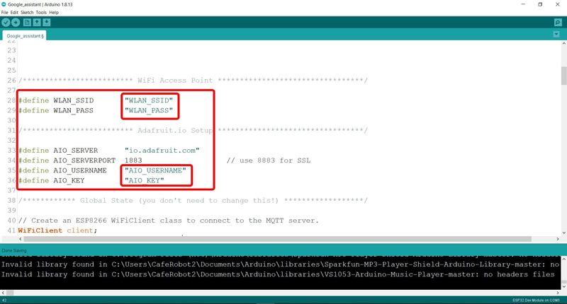
4 parts of the code are yet to be completed. They can have different values for each user. To complete the code, you should delete the phrase inside “X” and replace it with your desired values.
Tip
Do not forget to connect the VCC and the GND of the module to 5V and the GND of Arduino.
Those 4 parts are the following:
- WLAN_SSID: This is the name of the Wifi you want to connect the ESP32 to.
- WLAN_PASS: The password of the Wifi.
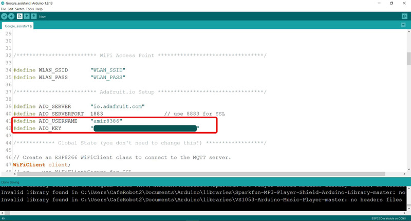
- AIO_USERNAME: This variable will be taken from “Adafruit-IO” website.
- AIO_KEY: This variable will also be taken from “Adafruit-IO” website later.
In the section describing Adafruit-IO, we will learn how to get the two variables “AIO_USERNAME” and “AIO_KEY”.
Register and Make a Project in Adafruit-IO
Step 1:
First, go to “io.adafruit.com” and make an account.
Step 2:
Log in to your account. Click on “+ New Dashboard” to make a new project and choose a title for it.
Step 3:
Now, you can make a new block by clicking on “Create New Block” section in the menu on the right. In this part, choose “Toggle” block, choose a name for it and click on “Create”. We have named it “LED”.
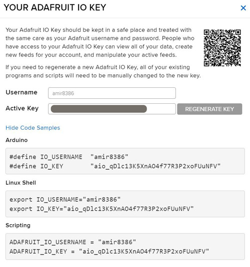
Step 4:
Now, you can copy the value of “Username” from “My Key” part and use that as the “AIO_USERNAME” variable in the code of the previous part. You can do the same thing for “Active Key” and copy its value for the “AIO_KEY” variable.
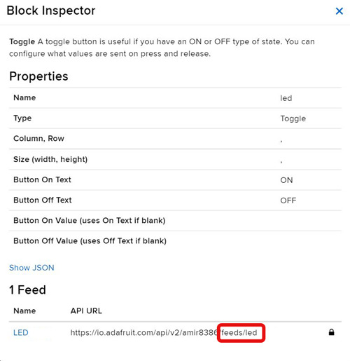
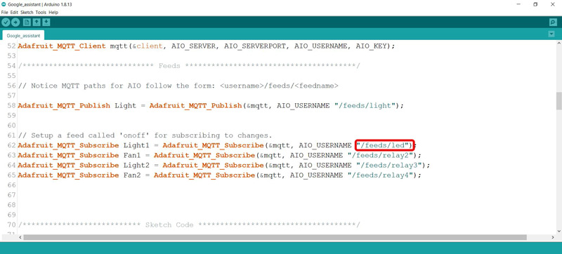
Step 5:
Click on “Edit Layout”, then, click on “Block Info” in the settings section. The last part of the “API URL”, meaning “/feed/led”, must be written in a part of the code. Do that according to the pictures below.
Full Video of the Steps in Adafruit-IO Website
The video below shows how to do the above stages in a detailed way:
Upload the Code on ESP32
We obtained the two parameters “AIO_USENAME” and “AIO_KEY” in the previous part. We also need to set the parameters “WLAN_SSID” and “WLAN_PASS” which are the Wifi username and password.
After setting these 4 parameters, we can upload the code on ESP32.
Note
While uploading, press and hold the “Boot” button to correctly upload the code on ESP32.
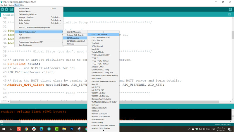
Make sure you have chosen the right Board and PORT, like the image below.
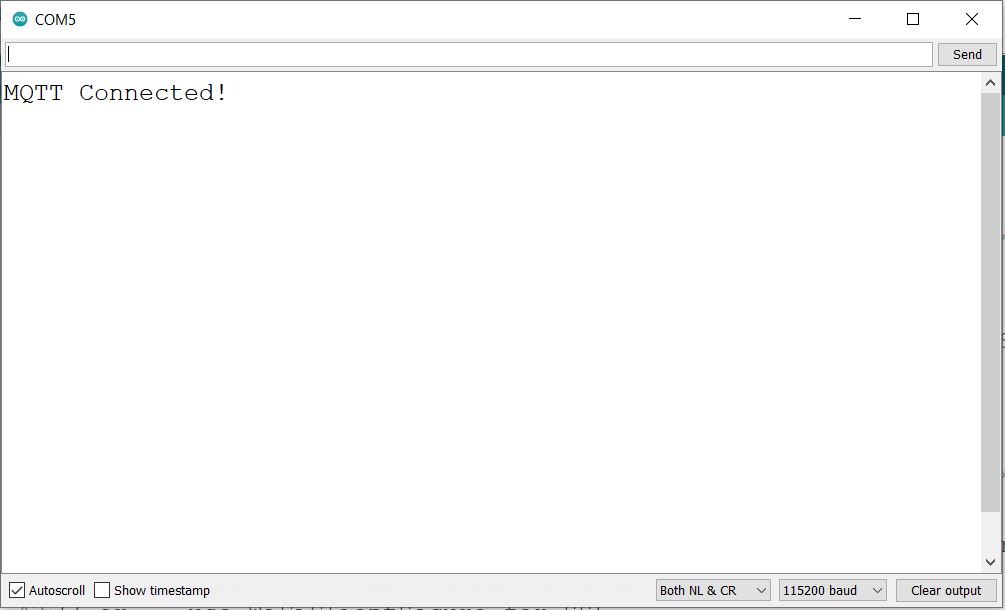
Once the code is successfully uploaded, open the Serial Monitor and set its baud rate to 115200. If everything has gone right, you should see the message “MQTT Connected!” on the output of Serial Monitor. This means the connection between the ESP32 and Adafruit-IO has been successfully established.
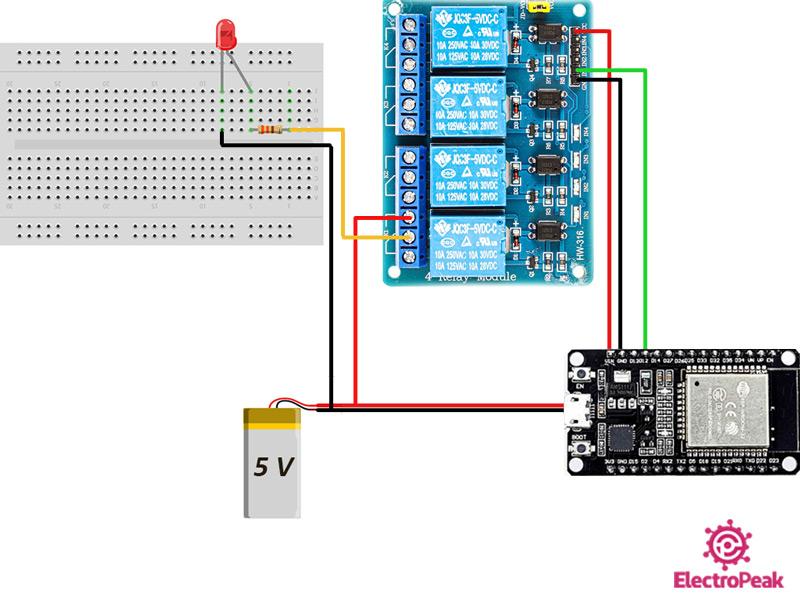
Step 2: Circuit
After uploading the code, connect the ESP32 to the relay module and the LED. The following image shows how you can do that.
Step 3: Connect IFTTT with Google Assistant & Adafruit-IO
First, go to “ifttt.com” and create an account.
Next, click on “Create”. At this moment, you will face two options: “This” and “That”. “This” is used for communicating with input and “That” is used for connecting the “IFTTT” to output. In this tutorial, the Google Assistant and Adafruit-OI communicate with the IFTTT as the input and output, respectively.
In other words, the IFTTT platform acts as a communication interface between Google Assistant and Adafruit-IO.
Connect to Google Assistant
To connect to Google Assistant, do the following steps:
Step 1:
After selecting the “This” option, search the phrase “Google Assistant” and open it.
Step 2:
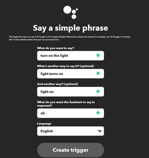
Select “Say a simple phrase”.
Step 3:
Write down your voice command in 3 different ways. Also, write the response you want to get from Google Assistant. At the end, select your desired language and click on “Create Trigger”.
For example, here are the setting for turning an LED on and off.
Note
Sometimes you need to confirm your email address to continue.
Of course, try to create all your accounts with the same email address so that there would be no problem in setting up.
Connect to Adafruit-IO
To connect to Adafruit-IO, do the following steps:
Step 1:
Click on “That”, search the word “Adafruit” and select it.
Step 2:
Select “Send data to Adafruit-IO”, then, select the name of the created block. You should also enter the desired pin value in ESP32 when the voice command in sent.

Note
If the relay module you’re using is Active Low, you should set the ESP32 pin to 0.
And if it is Active High, set the ESP32 pin to 1.
In this tutorial, we have used an Active Low relay module, that’s why we have set the ESP32 pin to 0.
Finally, click on “Continue”, then, “Finish”.
Do the same steps above for turning off the LED. The difference is that in the first part, you should use the word “Off” instead of “on”; and in the second part, put the value 1 instead of 0.
The two new created blocks can be seen in “My Applets” section.
Note
In the free trial of the “IFTTT” website, you are able to create only three new Applets.
The Video of the Steps in IFTTT Website
You can see how to do the above steps in a detailed way in the video below:
Step 4: Send the Voice Command Through Google Assistant
In this step, turn on the internet of your cell phone and open the Google Assistant. Say out loud the voice commands that you have entered the “IFTTT” website and see how the LED status changes. You can see the LED turning on and off in the video below.
What’s Next?
- Use other boards, like NodeMCU ESP8266
- Control the light of the LED using PWM
- Control 4 different devices
- Provide a new way to connect Google Assistant to the microcontroller
- Replace Adafruit-IO with Blynk application

Comments (31)
Thanks a lot for sharing
The server part is a bit vague to me. what should we do with the zip file? and where should we get the “URL of our Server to receive data”?
Hi, here is the URL you need: “http.begin(“http://31.184.135.137/api/Home/GetAllApp”
Hi, gif is so fast , that I am not able to read what’s in.
Hi, it is just a sample
Hi,
I can’t figure out where I can get the URL to enter in the first line of “that” on IFTTT. I’m new with this, what is this URL? I found a link on another site and the link simply didn’t work.
Thanks for your support
F-A
Hi.
Here it is. “http.begin(“http://31.184.135.137/api/Home/GetAllApp”);”
What do we do with the Server part?
download it, unzip it and?
You can check the following link for more details. “https://www.instructables.com/Control-House-Lights-With-Google-Assistant-Using-A/”
Hello .
How can i send data from Arduino to Google Assistant?
Hello…
Thanks a lot for the article it is really helpfull.
I would like to send data from arduino to Google Assistant , Do you know how do that?
Thanks in advance.
Hello.
First you need to alter the code provided for ESP-01 in the article to get data from Arduino via Serial port and send it to the database. Then change the other code for Arduino to send data to ESP-01. It’s pretty much like the original code of the this article. Good luck!
For the URL and server you would need to use an app like Blynk or an amazon hosting server. You can watch this video https://www.youtube.com/watch?v=5SvRolROPxA
Thanks so much for sharing!
I am getting a ESP8266Wifi.h: No such file or Directory Error (SEE BELOW:
Arduino: 1.8.10 (Mac OS X), Board: “Arduino/Genuino Uno”
ESP_WIFI:1:10: error: ESP8266WiFi.h: No such file or directory
#include “ESP8266WiFi.h”
^~~~~~~~~~~~~~~
compilation terminated.
exit status 1
ESP8266WiFi.h: No such file or directory
This report would have more information with
“Show verbose output during compilation”
option enabled in File -> Preferences.
Have you added the ESP8266WiFi.h library? Make sure it is properly added and let us know if the error persists.
follow the first few steps of the link below to add the esp8266 board. https://create.arduino.cc/projecthub/electropeak/getting-started-w-nodemcu-esp8266-on-arduino-ide-28184f
then in Tools->Board select the esp8266 board before uploading your code.
Hey, do we need premium iftttp for this or the normal one will work?
hello,
how can i build a project like jarvis in iron man. that can be answer my question?
Hi.
To get a good answer, you better give a little more details of the project you intend to do. You can also take a quick scan over our tutorials in this link and see if any of them can be useful for you. “https://electropeak.com/learn/”
Hi, I have to do this project with a bit different feature. can you please help me?
All I have to do is when we tell google assistant that I’m busy, the led color changes to red and when we tell itthat i’m available now, the led color changes to green.
Being a beginner i don’t know how to do that.
Hi.
The project you want to do is quite easy and almost the same as the project done in this tutorial. So, first, you better do the exact project explained in this article to get a good view on how you can make that small change and do your own project.
In overall, all you need to do is use an RGB LED, like this one: https://electropeak.com/4-pin-rgb-led. It has four pins, 3 for Red, Blue and Green and the other one is the common cathode pin. Using this LED, you can easily change its color using Google Assistant.
Hello and thanks for that nice job.
I’m working on a project and you helped me so much !
I’m stucked with a piece of code. What I’ve done : IFTTT and Adafruit are set up, I have 2 applets. The first is a slider which manage the brightness of a ws2812 ledstrip : when I say “hey google, put the light at 40 %”, it sends 40 to the esp32 and with :
…
uint8_t Brightness_State = atoi((char *)Brightness.lastread);
Brightness_State = map(Brightness_State, 0, 100, 0, 255);
…
I’m able to adjust brightness perfectly and it works !
The second one is a text applet, when I say “Hey google, set the light to blue”, it sends blue to the esp. I have 8 different colors so I decided to use a switch in the code. I first made an enum to set colors as int:
enum Colors {rouge, orange, jaune, verte, turquoise, bleue, violette, rose, blanche};
it works !
Serial.print(F(“Reçu: “));
Serial.println((char *)Couleur.lastread);
unsigned char * colors = (Couleur.lastread); (IT DOESN’T WORK because colors is not an int and the switch needs an int for colors!)
uint8_t Couleur_State;
switch (colors) {
case rouge:
Couleur_State = 0;
break;
case orange:
Couleur_State = 32;
break;
case jaune:
Couleur_State = 64;
break;
case verte:
Couleur_State = 96;
break;
case turquoise:
Couleur_State = 128;
break;
case bleue:
Couleur_State = 160;
break;
case violette:
Couleur_State = 192;
break;
case rose:
Couleur_State = 224;
break;
case blanche:
Couleur_State = 255;
break;
}
for(int i = 0; i < NUM_LEDS; i++) {
leds[i] = CHSV(Couleur_State,255,255);
};
FastLED.show();
Serial.println(Couleur_State);
…
How can I convert ((char *)Couleur.lastread) to an int or is there a way to do that ?
Hi.
You’re quite welcome! The input to a “switch case” must be an integer or a single character. So, in this case that you’re working with strings, you either need to use “if, else if” instead of “switch case” OR you can define a 2D string array assigning each color to a specific number. Then you can read the color, specify the number assigned to it, and use that as the case in your “switch case” statement.
Hello,
Thanks for your fast reply 😉 I’ve managed in the night with “if and else if” solution. It works….except for special effects with moving lights, they are freezed.
I’m using ESP32 module, so I decided to split the code on both cores as it exploits a little bit more the chip. I also use 1 push button (to switch between special effects in manual mode) and 2 potentiometers ( one to set brightness manually and the other one to switch between hue colors). When I use the push button special effects run normally, but when google calls it (the special effect) within the “if, else if”, it is switched on but it’s freezed (no moving lights as it should). So the next step is to try with the 2D string array in a “switch case” as it seems to not freezing the code… Have a nice day !
Wish you good luck! You have a nice day too.
First of all, many thanks for this article. My problem is that the serial monitor displays such messages from time to time (I will add that I have entered correctly WLAN_SSID” and „WLAN_PASS” ):
ets Jan 8 2013, rst cause: 4, boot mode: (3,6)
wdt reset
load 0x4010f000, len 1384, room 16
tail 8
chksum 0x2d
csum 0x2d
v482516e3
~ ld
⸮ r r⸮n # ⸮phAdafruit MQTT demo
Connecting to DawidziuNET
I corrected the library- My mistake sorry 🙂
It’s alright!
Is it possible to control more than 4 output?
What kind of pin I can use to do this work that are equivalent to pin 12-13-14-27?
Hi
for control more than 4 output you need more relay channel.
according to esp32 pinout schematic you can use 12-13-14-17 pins as outputs
Excellent project, unfortunately when I got to the Google Assist step the “say a simple phrase” item was no longer active, you could update your tutorial with Google Assist V2. Thank you