
ZMCT103C Current Transformer Module Features
The ZMCT103C AC current transformer module can be used to monitor current in various applications. This module is based on ZMCT103C IC. The mechanism of this IC is that the wire whose current is to be measured, passes through the hole of the IC. Then, according to AC current, voltage is induced on both sides of IC.
In this module, the output voltage of ZMCT103C IC is amplified by a series of amplifiers and can be used as the module output. The module outputs an analog AC voltage corresponding to AC current of the wire passing through the module hole.
Note
There is an onboard potentiometer which you can adjust amplification factor by turning the volume.
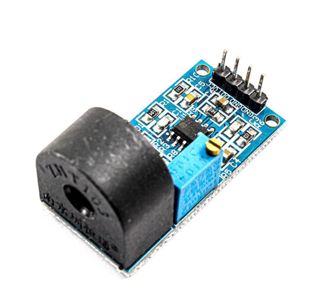
ZMCT103C Current Transformer Module Pinout
This Module has 4 pins:
- VCC: Module power supply – 5V
- OUT: Module Output
- GND: Ground
- GND: Ground
You can see the pinout of this module in the image below.
Required Material
Hardware component
Software Apps
Interfacing ZMCT103C Current Transformer Module with Arduino
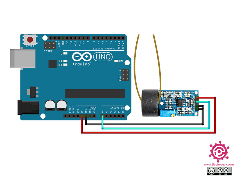
Step 1: Circuit
Connect the module to Arduino according to the circuit below and pass the wire which you want to measure the current through the hole.
Step 2: Code
Upload the following code to your Arduino. After that open Serial Monitor.
 /*
Made on Dec 22, 2020
By MehranMaleki @ Electropeak
Home
*/

#define calibration_const 355.55
int max_val;
int new_val;
int old_val = 0;
float rms;
float IRMS;

void setup() {
  pinMode(A0,INPUT);
  Serial.begin(9600);
}

void loop() {
  new_val = analogRead(A0);
  if(new_val > old_val) {
    old_val = new_val;
  }

  else {
    delayMicroseconds(50);
    new_val = analogRead(A0);
    if(new_val < old_val) {
      max_val = old_val;
      old_val = 0;
    }

    rms = max_val * 5.00 * 0.707 / 1024;
    IRMS = rms * calibration_const;

    Serial.print("  IRMS: ");
    Serial.println(IRMS);

    delay(1000);
  }
}
To calibrate the module, we first need to calculate the output voltage for an AC current which we already know its current. Therefore, the calibration coefficient can be easily calculated. (Coefficient will changes as you turn the potentiometer). In above code, the A0 pin is used to read output voltage. Then, by calculating the maximum voltage in different ranges, the rms current passing through the wire is obtained. Also, to test the code performance, we have measured the current passing through the wire of a soldeing station.
The output is as follows. (Values are in terms of mA.)

Comments (6)
Can anyone help me to explore circuit diagram of this board.
Is the calibration const a value of millivolts or milli Amps or Ohms? What is the unit of Calibration const?
Hello,
The output values are in mA.
Calibrate the readings using a multimeter as a reference.
How did you measure the calibration constant? Can you please layout the procedure?
Hello Muhammad,
We use a multimeter as a reference, then measure the current passing through a lamp. This value is used to calibrate our sensor. We also test with components of lower and higher current to verify accuracy.
Hi Mohammad,
When I give power supply to this module +5v and check ADV output without any load, it gives 0.12v AC.
Is it correct? If not, then what should be output AC coltage of this sensor in the absence of any load.
Regards,
Junaid