
Are you tired of having a desk cluttered with wires? Do you want to get rid of them? Well, we have a solution for that!
In this tutorial, we’ll introduce you the nRF24L01 module, which is one of the most popular modules for wireless communication. Whether you are a beginner or experienced user, you’ll learn a new way to send and receive data.
In this tutorial, we will explore the functionality of the nRF24L01 module and show you how to interface it with Arduino and ESP32/8266-based boards to create wireless communication systems.
What You Will Learn
- The basics of the nRF24L01 transceiver module
- How to choose the right nRF24L01 module for your project
- The best nRF24L01 libraries for Arduino
- How to create a two-way transceiver system with the nRF24L01 module
- The concept of nRF24L01 mesh networks and how they work
- A practical example of a nRF24L01 mesh network using ESP32 and DHT22 temperature sensors
nRF24L01 Modules - Introduction
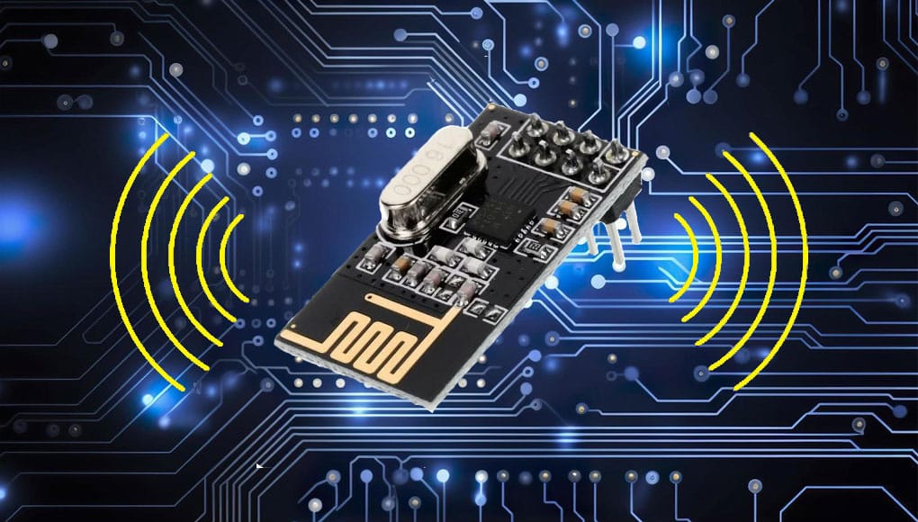
The nRF24L01 is a popular wireless transceiver module developed by Nordic Semiconductor. This module works in the 2.4 GHz ISM band and is widely used for short-range communication in various electronic projects, including remote control systems, sensor networks, and Internet of Things projects, due to its simplicity and wireless connections. With dimensions of about 15×28 mm, it is also suitable for projects with limited space.
The important features of the nRF24L01 module are as follows:
- 2.4 GHz antenna on board
- 100-meter range (without obstacles and with a direct view in a noise-free environment)
- Adjustable data exchange rate from 250 Kbps to 2 Mbps
- Auto acknowledge
- Re-Transmit Auto
- Multiceiver with 6 data pipes
- 32 bytes of FIFO, separately for TX and RX
- Input pins with voltage tolerance of 5V
- Communication channel from 2400 MHz to 2525 MHz (125 selectable channels)
- Minimal need for peripherals for setup
nRF24L01 Modules – How They Work?
Radio communication modules have different settings and configurations; we will discuss some of the most important ones, including the nRF24L01 module.
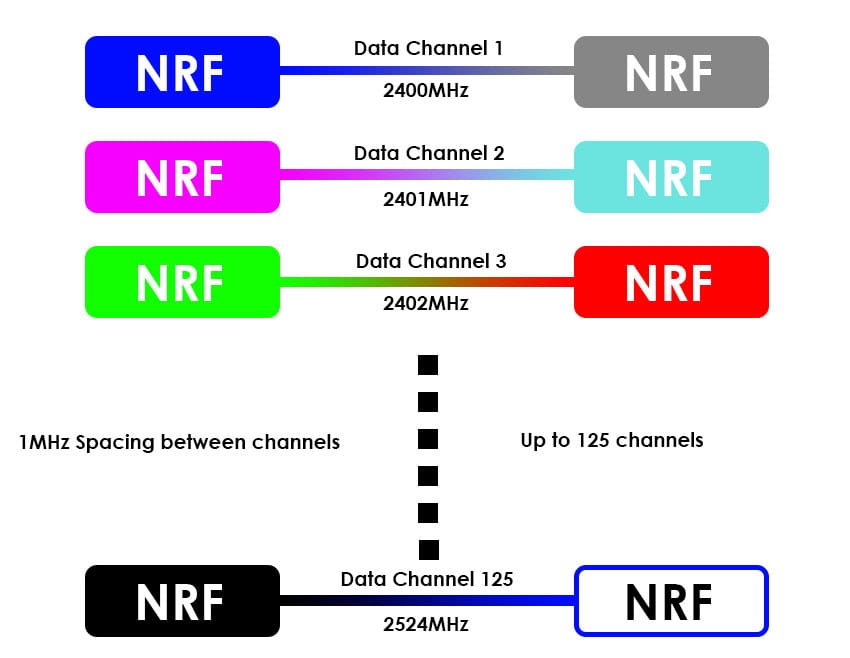
Communication Channel Frequency of nRF24L01
The nRF24L01 modules transmit and receive data on a specific frequency known as a “channel.” To prevent data interference between two or more modules that need to communicate with each other in the same environment, they must be on separate channels. This channel can have any frequency in the 2.4 GHz ISM band, between 2.400 GHz and 2.525 GHz (2400 MHz and 2525 MHz) to be precise.
Each channel occupies less than 1 MHz of bandwidth, which means there are 125 separate channels in the above range. Therefore, you can have 125 separate connections between nRF24L01 modules in one specific environment.
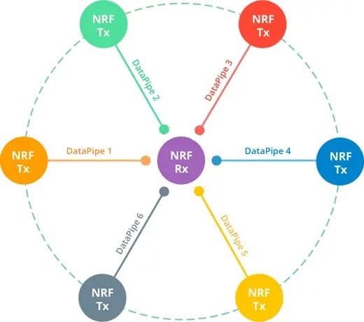
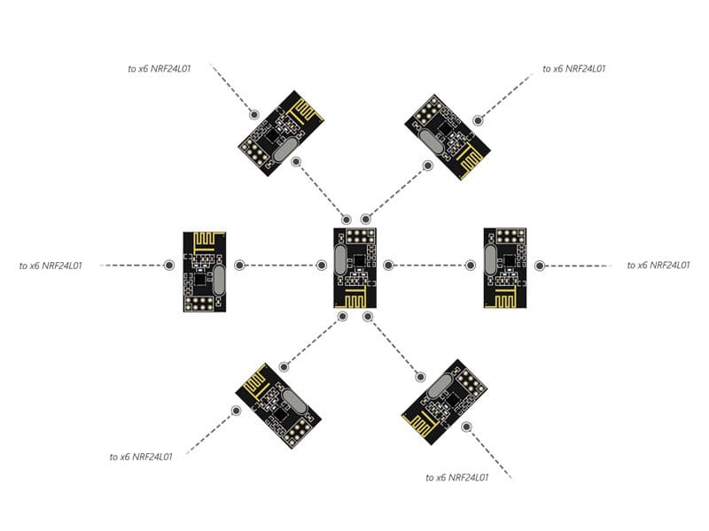
Multiceiver Network with nRF24L01
The nRF24L01 module features a Multiceiver function, which stands for Multiple Transmitter Single Receiver.
In a multi-receiver network, each RF channel is logically separated into six parallel data channels called a “pipeline.” A pipe refers to one of the six logical channels in a physical RF channel, each with its unique address known as the Data Pipe address. However, only one Data Pipe can receive a package at a time.
The image below shows a multi-receiver network.
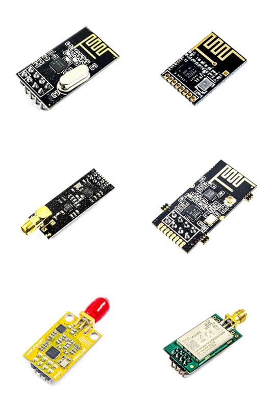
nRF24L01 Modules: Comparison
Before purchasing an nRF24L01 module, it is essential to understand the differences between the models available in the market to select the right one. The following are the main differences:
Power Amplification (PA) and Low Noise Amplification (LNA): Some modules come with Power Amplification (PA) and Low Noise Amplification (LNA) features that increase the communication range. These modules are often labeled as “nRF24L01+PA+LNA”. Here’s an example of one such module.
External antenna installation: various modules may have different antenna configurations. Some have an internal antenna, while others have an external antenna connection to increase range. Here’s an example of a module with an external antenna.
Voltage range: Although most modules operate in the 3.3 V range, the working voltage range may differ among modules. Therefore, it is necessary to pay attention to this parameter when selecting a module.
Data rate: The maximum data rate supported by the nRF24L01 module may vary. While the standard data rate is 250 kbps, some modules can support higher rates, such as 1 Mbps or 2 Mbps.
Effective range: The distance for effective communication can vary depending on factors such as PA/LNA, antenna type, and environmental conditions. Some modules may provide a greater range than others.
Cost: The cost of nRF24L01 modules may vary based on features and specifications. Modules with more features, such as external antennas or PA/LNA, may be more expensive than others.
Manufacturer and Brand: Various manufacturers produce nRF24L01 modules. Therefore, the quality of the components used in them can vary, leading to differences in the quality of sending and receiving data.
The image below shows the types of nRF24L01 modules.
nRF24L01 Vs. nRF24L01+PA/LNA
The nRF24L01 and nRF24L01+PA/LNA modules are two versions of the popular wireless transceiver module developed by Nordic Semiconductor. Despite many similarities, they have key differences.
The PA/LNA+nRF24L01 chip includes a Power Amplifier (PA) which amplifies the transmitted signal, and a Low-Noise Amplifier (LNA) which amplifies the very weak signal received from the antenna (usually sub-microvolts or -100dBm) to a more manageable voltage level (usually around 0.5 to 1V).
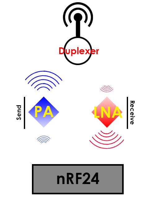
The Duplexer isolates the two signals and prevents the relatively powerful PA output from interfering with the sensitive LNA input.
Now, let’s compare the nRF24L01 and nRF24L01+PA/LNA modules:
The nRF24L01 module:
This module is the original version without external PA or LNA. It has a limited range, usually suitable for short-range communication within a room up to a few meters.
In addition, it usually comes with a built-in PCB antenna, which is compact but may reduce the effective communication range. The nRF24L01 is usually less expensive and consumes less power compared to the PA and LNA type.
The nRF24L01+PA/LNA module:
On the other hand, the nRF24L01+PA/LNA module includes an external power amplifier (PA) and low-noise amplifier (LNA), which significantly increases the communication range. This module is designed for applications that require greater range and improved signal strength. It may come with an external antenna or an antenna connector, providing the flexibility to use different types of antennas for further customization. However, adding PA/LNA components may increase the power consumption slightly compared to the original nRF24L01 module.
nRF24L01 Modules: Range Boost
If you want to increase the range of nRF24L01 modules, there are a few things to consider:
- Antenna upgrade: One of the most effective ways to improve the range is to upgrade the transmitter and receiver antennas. You can replace the internal PCB antenna with an external antenna.
Using antennas with higher dBi gain, such as a 2.4 GHz antenna with a gain of 2 dBi or higher, will provide better performance.
- Capacitor location: Place the capacitors near the Vcc and GND pins of the nRF24L01 modules to stabilize the power supply and filter noise.
- Data Rate Reduction: Data rate reduction can improve the coverage area. You can give it a test with a lower data rate to see if it meets your needs.
- PA/LNA modules: some nRF24L01 modules have an internal power amplifier (PA) and low noise amplifier (LNA), which provide a better range compared to standard ones.
- Interference Reduction: Minimize interference from other electronic devices operating within the 2.4 GHz range. Wi-Fi routers, microwave ovens, and other wireless devices can impact the nRF24L01 module’s performance.
- Signal strength and RSSI: Check the received signal strength indicator (RSSI) to help measure signal quality. You can use this information to optimize module placement for better communication.
- Direct line of sight (LOS): Ensure a clear line of sight between the transmitter and receiver, if possible. Obstacles such as walls and other physical objects can significantly reduce the effective range.
nRF24L01 Module: Applications
Here are some common applications of nRF24L01:
- Wireless sensor networks: the nRF24L01 module is widely used for wireless sensor networks where multiple sensor nodes communicate with a central controller or with each other. These networks are commonly used in home automation, industrial monitoring, and environmental
- Remote control systems: This module is often used for remote control applications, such as drones, robotic systems, or any device that requires wireless command and control.
- IoT projects: nRF24L01 enables communication between different IoT devices, allowing them to exchange data wirelessly. This is useful for applications such as smart home systems, wearable devices, and more.
- Data logging and telemetry: nRF24L01 can wirelessly transmit data from remote locations to a data logging center or monitoring station. This is especially valuable in scenarios where using physical cables is impractical.
- Low-power applications: the nRF24L01 module is suitable for battery-operated devices and extends the operating life of devices in applications where energy efficiency is critical.
nRF24L01 Module: Pinouts
The nRF24L01 module has 8 pins as shown in the image below. Modules with PA and LNA also have the same pin arrangement.
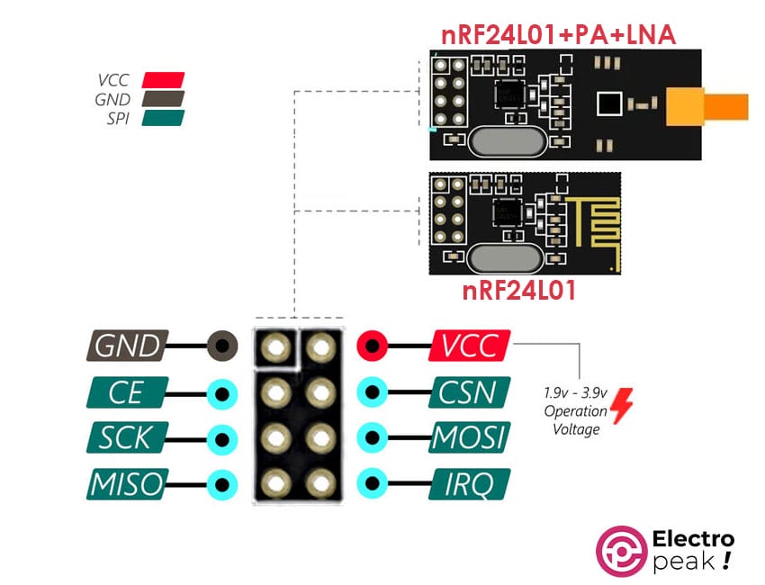
Here are the pin functions:
- VIN: module power supply (1.9 to 3.9 V)
- GND: Ground
- MOSI: data transmission line for SPI protocol
- MISO: data receiving line for SPI protocol
- SCK: Synchronization for SPI protocol
- IRQ: Interrupt for SPI protocol
- CSN: module selection for SPI protocol (reverse)
- CE: SPI protocol activation
Popular nRF24L01 Libraries for Arduino
There are several Arduino libraries to work with the nRF24L01 transceiver modules. Below are some popular libraries for interfacing nRF24L01 with Arduino. (You can download them if you want.)
TMRh20 RF24 (RF24Network, RF24Mesh): Developed by TMRh20, this library extends the RF24 library by adding features such as network and mesh functionality. RF24Network creates network structures, and RF24Mesh provides mesh network capabilities.
Mirf: The Mirf library makes it easy to use nRF24L01 modules by providing a simple interface. It is suitable for beginners and those who just want to get familiar with this module.
Maniacbug NRF24L01: This library provides a strong and well-documented set of functions for working with nRF24L01 modules. It supports various configurations and is known as one of the most reliable libraries.
Required Materials
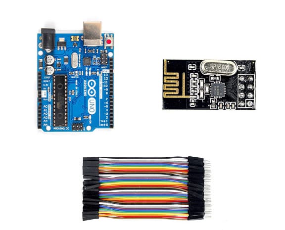
To build a server or client, you will need the following components. Determine how many you need according to your project.
*: You can also use any other Arduino or ESP32/8266 board.
Below, you can see the types of NRF24L01 modules. You need at least 2 of them for communication, and they don’t need to be the same model.
Interfacing “nRF24L01” Transceiver Module with Arduino
Step 1: Wiring
Connect the SPI pins of Arduino to the SPI pins of the nRF24L01 module as shown below. You need two of the following circuits to create a transmitter and receiver.
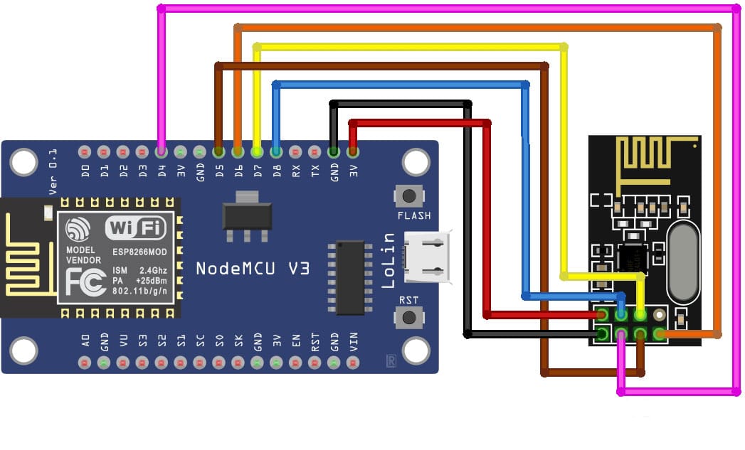
If you want to use the NodeMCU module instead of the Arduino UNO, connect the SPI pins of the NodeMCU board to the SPI pins of the nRF24L01 module as shown below. Since the power supply for this board is 3.3V, you can use this pin to power the nRF24L01 module. Each of the NodeMCU modules below has the same pinout layout.
- NodeMcu development board with ESP8266 Wi-Fi core and CH340 converter
- NodeMcu development board with ESP8266 Wi-Fi core and CP2102 converter (type C)
- NodeMcu development board with ESP8266 Wi-Fi core and CP2102 converter
Step 2: Installing Library
Install the Maniacbug NRF24L01 library —introduced in the previous sections— on the Arduino software.
Step 3: Arduino Code for nRF24L01 Receiver
Upload the following code on the Arduino of the receiver side. (Read the comments to fully understand how the code works.)
					/*
   nRF24L01
   modified on Sep 8, 2020
   by Mohammed Damirchi @ ElectroPeak
   https://electropeak.com/
*/

/* 1 ch NRF 24 TRANSMITTER example.

  Module // Arduino UNO //        ESP32
    GND    ->   GND           ->  GND
    Vcc    ->   3.3V(External)->  3.3v
    CE     ->   D9            ->  D4
    CSN    ->   D10           ->  D5
    CLK    ->   D13           ->  D18
    MOSI   ->   D11           ->  D23
    MISO   ->   D12           ->  D19
*/

/* First we include the libraries.
*/
#include <SPI.h>
#include <nRF24L01.h>
#include <RF24.h>
#include <printf.h>

/*//////////////////////////////////////////////////////*/

#if defined(__AVR_ATmega328P__) || defined(__AVR_ATmega328PB__) ||defined(__AVR_ATmega2560__) || defined(__AVR_ATmega1280__)
#define CSN 10
#define CE  9
#elif defined(ESP32)
#define CSN 5
#define CE  4
#else
#error "Make Config you're self"
#endif

#define Debug_mode false

/*Create a unique pipe out. The receiver has to
  wear the same unique code*/
const uint64_t pipeIn = 0x662266; //IMPORTANT: The same as in the receiver!!!
/*//////////////////////////////////////////////////////*/

/*Create the data struct we will send
  The sizeof this struct should not exceed 32 bytes
  This gives us up to 32 8 bits channals */
RF24 radio(CE, CSN); // select  CSN and CE  pins


/*//////////////////////////////////////////////////////*/
//Create a struct to send over NRF24L01
struct MyData {
  byte test;
};
MyData data;
/*//////////////////////////////////////////////////////*/

//This function will only set the value to  0 if the connection is lost...
void resetData()
{
  data.test = 0;
}


/**************************************************/

void setup()
{
  pinMode(LED_BUILTIN, OUTPUT);
  Serial.begin(9600); //Set the speed to 9600 bauds if you want.
  //You should always have the same speed selected in the serial monitor
  resetData();
  radio.begin();
  if (Debug_mode)
    printf_begin();
  radio.setDataRate(RF24_250KBPS); //speed  RF24_250KBPS for 250kbs, RF24_1MBPS for 1Mbps, or RF24_2MBPS for 2Mbps
  radio.openWritingPipe(pipeIn);//Open a pipe for writing
  radio.openReadingPipe(1, pipeIn);//Open a pipe for reading
  radio.openReadingPipe(2, pipeIn);//Open a pipe for reading
  radio.openReadingPipe(3, pipeIn);//Open a pipe for reading
  radio.openReadingPipe(4, pipeIn);//Open a pipe for reading
  radio.openReadingPipe(5, pipeIn);//Open a pipe for reading
  radio.setAutoAck(true); // Ensure autoACK is enabled
  radio.setChannel(108);// Set RF communication channel.
  radio.setPALevel(RF24_PA_MAX); //translate to: RF24_PA_MIN=-18dBm, RF24_PA_LOW=-12dBm, RF24_PA_MED=-6dBM, and RF24_PA_HIGH=0dBm.
  radio.enableDynamicPayloads(); //This way you don't always have to send large packets just to send them once in a while. This enables dynamic payloads on ALL pipes.
  //radio.disableDynamicPayloads();//This disables dynamic payloads on ALL pipes. Since Ack Payloads requires Dynamic Payloads, Ack Payloads are also disabled. If dynamic payloads are later re-enabled and ack payloads are desired then enableAckPayload() must be called again as well.
  radio.setCRCLength(RF24_CRC_16); // Use 8-bit or 16bit CRC for performance. CRC cannot be disabled if auto-ack is enabled. Mode :RF24_CRC_DISABLED  ,RF24_CRC_8 ,RF24_CRC_16
  radio.setRetries(10, 15);//Set the number of retry attempts and delay between retry attempts when transmitting a payload. The radio is waiting for an acknowledgement (ACK) packet during the delay between retry attempts.Mode: 0-15,0-15
  radio.startListening();//Start listening on the pipes opened for reading.
}


/******Reset the received data to 0 if connection is lost******/
unsigned long lastRecvTime = 0;
void recvData()
{
  while ( radio.available() )//Check whether there are bytes available to be read
  {
    radio.read(&data, sizeof(MyData));//Read payload data from the RX FIFO buffer(s).
    lastRecvTime = millis(); //here we receive the data
  }
}
/**************************************************************/


void loop()
{
  recvData(); //Resive Data
  unsigned long now = millis();
  //Here we check if we've lost signal, if we did we reset the values
  if ( now - lastRecvTime > 1000 ) {
    // Signal lost?
    resetData();
  }
  Serial.print("Resive Value: "); Serial.println(data.test);
  analogWrite(LED_BUILTIN, data.test);
  delay(100);
  if (Debug_mode)
    radio.printDetails();//Show debug data
}
Code Cracking
In this section, we will explain the important lines of the above code:
- Line 49: Creates the object required for the module by specifying the CS and CSN pins
RF24 radio(CE, CSN); // select CSN and CE pins
- Line 78: Determines the data transfer speed
radio.setDataRate(RF24_250KBPS);
- Line 79: Specifies the receiver for the transmitter
radio.openWritingPipe(pipeIn);
- Lines 80 to 84: Specifies the transmitter for the receiver(s).
radio.openReadingPipe(1, pipeIn);
- Line 85: Activates the Auto Acknowledgment feature
radio.setAutoAck(true);
- Determines the radio channel
radio.setChannel(108);
- Line 87: Specifies the power consumption for the module. This value should be determined according to the distance between the transmitter and receiver.
radio.setPALevel(RF24_PA_MAX);
- Line 90: Sets the length of the CRC phrase
radio.setCRCLength(RF24_CRC_16);
- Line 92: receiver mode activation
radio.startListening();
- Line 101: Waiting for data entry
while ( radio.available() )
- Line 103: Receiving data from RF
radio.read(&data, sizeof(MyData));
Step 4: Arduino Code for nRF24L01 Transmitter
Upload the following code on the Arduino of the transmitter side. (Read the comments to fully understand how the code works.)
					/*
nRF24L01
modified on Sep 8, 2020
by Mohammed Damirchi @ ElectroPeak
https://electropeak.com/
*/


/* 1 ch NRF 24 TRANSMITTER example.

  Module // Arduino UNO //        ESP32
    GND    ->   GND           ->  GND
    Vcc    ->   3.3V(External)->  3.3v
    CE     ->   D9            ->  D4
    CSN    ->   D10           ->  D5
    CLK    ->   D13           ->  D18
    MOSI   ->   D11           ->  D23
    MISO   ->   D12           ->  D19
*/

/* First we include the libraries. Download it from
   my webpage if you donw have the NRF24L01 library */
#include <SPI.h>
#include <nRF24L01.h>
#include <RF24.h>
#include <printf.h>

/*//////////////////////////////////////////////////////*/

#if defined(__AVR_ATmega328P__) || defined(__AVR_ATmega328PB__) ||defined(__AVR_ATmega2560__) || defined(__AVR_ATmega1280__)
#define CSN 10
#define CE  9
#elif defined(ESP32)
#define CSN 5
#define CE  4
#else
#error "Make Config you're self"
#endif

#define Debug_mode false


/*Create a unique pipe out. The receiver has to
  wear the same unique code*/
const uint64_t pipeOut = 0x662266; //IMPORTANT: The same as in the receiver!!!
/*//////////////////////////////////////////////////////*/

/*Create the data struct we will send
  The sizeof this struct should not exceed 32 bytes
  This gives us up to 32 8 bits channals */

RF24 radio(CE, CSN); // select  CSN and CE  pins


/*//////////////////////////////////////////////////////*/
//Create a struct to send over NRF24L01
struct MyData {
  byte test;
};
MyData data;
byte count = 0;
/*//////////////////////////////////////////////////////*/


//This function will only set the value to  0 if the connection is lost...
void resetData()
{
  data.test = 0;
}

void setup()
{
  Serial.begin(9600);
  if (Debug_mode)
    printf_begin();
  radio.begin();
  radio.setDataRate(RF24_250KBPS); //speed  RF24_250KBPS for 250kbs, RF24_1MBPS for 1Mbps, or RF24_2MBPS for 2Mbps
  radio.openWritingPipe(pipeOut); //Open a pipe for writing
  radio.openReadingPipe(0, pipeOut); //Open a pipe for reading
  radio.setChannel(108);// Set RF communication channel.
  radio.setPALevel(RF24_PA_MAX); //translate to: RF24_PA_MIN=-18dBm, RF24_PA_LOW=-12dBm, RF24_PA_MED=-6dBM, and RF24_PA_HIGH=0dBm.
  radio.enableDynamicPayloads(); //This way you don't always have to send large packets just to send them once in a while. This enables dynamic payloads on ALL pipes.
  //radio.disableDynamicPayloads();//This disables dynamic payloads on ALL pipes. Since Ack Payloads requires Dynamic Payloads, Ack Payloads are also disabled. If dynamic payloads are later re-enabled and ack payloads are desired then enableAckPayload() must be called again as well.
  radio.setCRCLength(RF24_CRC_16); // Use 8-bit or 16bit CRC for performance. CRC cannot be disabled if auto-ack is enabled. Mode :RF24_CRC_DISABLED  ,RF24_CRC_8 ,RF24_CRC_16
  radio.setRetries(10, 15);//Set the number of retry attempts and delay between retry attempts when transmitting a payload. The radio is waiting for an acknowledgement (ACK) packet during the delay between retry attempts.Mode: 0-15,0-15
  radio.setAutoAck(true); // Ensure autoACK is enabled
  radio.stopListening();//Stop listening for incoming messages, and switch to transmit mode.
  resetData();

}

/**************************************************/

void loop()
{
  count++;
  data.test = count;//fill data to MyData
  Serial.print("Send");
  Serial.println(count);
  if (count == 254) {
    count = 0;
  }
  NRF24L01_Transmit();//Transmit MyData
  delay(200);
}

void NRF24L01_Transmit() {
  radio.writeFast(&data, sizeof(MyData));//Transmit Data. use one of this two: write() or writeFast()
  if (Debug_mode)
    radio.printDetails();//Show debug data
  bool OK = radio.txStandBy();//Returns 0 if failed. 1 if success.
  delayMicroseconds(50);
  radio.flush_tx();//Empty all 3 of the TX (transmit) FIFO buffers
}
Code Cracking
Read the code cracking of the receiver section.
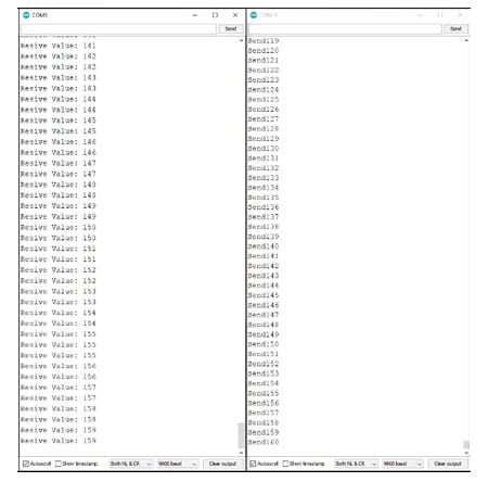
Step 5: Run the code
After uploading the transmitter and receiver codes to your microcontrollers, open the Serial Monitor window of the Arduino software for both of them. You will see the transmitted and received data.
Create A Network with nRF24L01, Exchange Data between Them, and Display it on Web Server
In this part, we will learn how to create a wireless mesh network (image below) using nRF24L01. This method for data exchange is more effective when tasks require simultaneous communication with several stations (nodes).
The central node in this network acts as a base node and has two general tasks. First, it collects the data sent from other nodes, and then uploads them to the web server. You can modify the data sent by each node according to your needs by changing the code.
Here’s what you need to do step by step:
Step 1: Installing Libraries
First, download the following libraries and install them on the Arduino software.
Step 2: Sub-Nodes - Wiring
Similar to the circuit in the previous section, connect the Arduino SPI pins to the nRF24L01 module.
All transmitter nodes have the same wiring. Just change the sensor (which is a potentiometer here) to transmit the data read from it through the nRF24L01 network.
Step 3: Code for Sub-Nodes (Client)
The code below includes comments. You can read them to fully understand how the code works.
					/*
nRF24L01 Network
modified on Jan 8, 2024
by Majid Merati @ ElectroPeak
https://electropeak.com/
*/

#include <RF24Network.h>
#include <RF24.h>
#include <SPI.h>

#if defined(__AVR_ATmega328P__) || defined(__AVR_ATmega328PB__) ||defined(__AVR_ATmega2560__) || defined(__AVR_ATmega1280__)
#define CSN 10
#define CE  9
#elif defined(ESP32)
#define CSN 5
#define CE  4
#elif defined(ESP8266)
#define CSN D0
#define CE  D4
#else
#error "Make Config you're self"
#endif

RF24 radio(CE, CSN);     //RF24 (CE,CSN)
RF24Network network(radio);      // Include the radio in the network
const uint16_t Base_node = 00;   // Address of the base node in Octal ( 04,031, etc)
const uint16_t this_node = 01;    // Address of this node node in Octal

const unsigned long interval = 1000;  //How often to send data to the base unit (ms)
unsigned long last_sent;            // last time we sent data

void setup() {
  SPI.begin();
  Serial.begin(9600);
  radio.begin();
  network.begin(90, this_node);  //(channel, node address)
  radio.setDataRate(RF24_250KBPS);
}

void loop() {
  network.update();

  unsigned long now = millis();
  if (now - last_sent >= interval) {   // If it's time to send a data, send it!
    last_sent = now;
    unsigned long temperature = analogRead(A0);
    Serial.println(temperature);
    RF24NetworkHeader header(Base_node);   // (Address where the data is going)
    bool ok = network.write(header, & temperature, sizeof(temperature)); // Send the data to base node
  }
}
After uploading the code on Arduino, the analog value of pin A0 is read every second and sent to the base node through nRF24L01.
As mentioned, you can connect any sensor to Arduino and read and send its value. Most of the sensors in the Electropeak store have setup tutorials that you can read if you need to.
Step 4: Wiring the Base Node (Server)
In the base node, we used the NodeMCU board to display data on a web server. Wire the base node according to the image in the previous section in which we connected the nRF24L01 module to the NodeMCU.
Step 5: Base Node Code
The code below includes comments. You can read them to fully understand how the code works.
					/*
nRF24L01 Network
modified on Jan 8, 2024
by Majid Merati @ ElectroPeak
https://electropeak.com/
*/


#include <ESP8266WiFi.h>
#include <WiFiClient.h>
#include <ESP8266WebServer.h>
#include <ESP8266mDNS.h>

#include <RF24Network.h>
#include <RF24.h>
#include <SPI.h>

#ifndef STASSID
#define STASSID "************"     //Please type your Wifi network SSID
#define STAPSK  "************"  //Please type your Wifi network Pass
#endif

const char *ssid = STASSID;
const char *password = STAPSK;

ESP8266WebServer server(80);    //Server port No.

#if defined(__AVR_ATmega328P__) || defined(__AVR_ATmega328PB__) ||defined(__AVR_ATmega2560__) || defined(__AVR_ATmega1280__)
#define CSN 10
#define CE  9
#elif defined(ESP32)
#define CSN 5
#define CE  4
#elif defined(ESP8266)
#define CSN D0
#define CE  D4

int analog_read[10];

RF24 nRF (CE, CSN);               // nRF24L01 (CE,CSN)
RF24Network network(nRF);     // Include the radio in the network
const uint16_t Base_node = 00;   // Address of this node in Octal format ( 04,031, etc)
const uint16_t node01 = 01;   // Address of the other node in Octal format
const uint16_t node02 = 02;
const uint16_t node03 = 03;


void handleRoot() {
  char temp[400];
  int sec = millis() / 1000;
  int min = sec / 60;
  int hr = min / 60;

  snprintf(temp, 400,

           "<html>\
  <head>\
    <meta http-equiv='refresh' content='5'/>\
    <title>ESP8266 Data Server</title>\
    <style>\
      body { background-color: #000000; font-family: Arial, Helvetica, Sans-Serif; Color: #ffff00; }\
    </style>\
  </head>\
  <body>\
    <h1>Analog data charts</h1>\
    <p>Uptime: %02d:%02d:%02d</p>\
    <img src=\"/test.svg\" />\
  </body>\
</html>",

           hr, min % 60, sec % 60
          );
  server.send(200, "text/html", temp);
}

void handleNotFound() {
  String message = "File Not Found\n\n";
  message += "URI: ";
  message += server.uri();
  message += "\nMethod: ";
  message += (server.method() == HTTP_GET) ? "GET" : "POST";
  message += "\nArguments: ";
  message += server.args();
  message += "\n";

  for (uint8_t i = 0; i < server.args(); i++) {
    message += " " + server.argName(i) + ": " + server.arg(i) + "\n";
  }
  server.send(404, "text/plain", message);
}

void drawGraph() {
  String out;
  out.reserve(750);
  char temp[70];
  out += "<svg xmlns=\"http://www.w3.org/2000/svg\" version=\"1.1\" width=\"400\" height=\"150\">\n";
  out += "<rect width=\"400\" height=\"150\" fill=\"rgb(100, 100, 100)\" stroke-width=\"2\" stroke=\"rgb(210, 210, 0)\" />\n";
  out += "<g stroke=\"yellow\">\n";
  unsigned long Temperature;
  network.update();   //Update the network state
  while ( network.available() ) {     // Is there any incoming data?
    RF24NetworkHeader header;
    network.read(header, &Temperature, sizeof(Temperature));    //Read incoming data and store it

    if (header.from_node == 1) {    // If data comes from Node 01
      //Serial.println(Temperature);
      for (int j = 0; j < 10; j++)    //store read value on array to show on graph
      {
        analog_read[j] = analog_read[j + 1];
      }
      analog_read[9] = map(Temperature, 0, 1023, 0, 130);

      for (int x = 0; x < 10; x++)
      {
        sprintf(temp, "<line x1=\"%d\" y1=\"%d\" x2=\"%d\" y2=\"%d\" stroke-width=\"1\" />\n", x * 44, 140 - analog_read[x], (x + 1) * 44, 140 - analog_read[x + 1]);
        out += temp;
      }
      out += "</g>\n</svg>\n";
      server.send(200, "image/svg+xml", out);
    }
    if (header.from_node == 2) {    // If data comes from Node 02
      digitalWrite(13, HIGH);  // Turn on the LED
      delay(100);
      digitalWrite(13, LOW);   //// Turn off the LED
    }
  }


}

void setup(void) {
  SPI.begin();
  nRF.begin();
  network.begin(90, Base_node);  //(channel, node address)
  nRF.setDataRate(RF24_250KBPS);
  pinMode(button, INPUT_PULLUP);
  pinMode(led, OUTPUT);

  Serial.begin(115200);
  WiFi.mode(WIFI_STA);
  WiFi.begin(ssid, password);
  Serial.println("");

  // Wait for connection
  while (WiFi.status() != WL_CONNECTED) {
    delay(500);
    Serial.print(".");
  }

  Serial.println("");
  Serial.print("Connected to ");
  Serial.println(ssid);
  Serial.print("IP address: ");
  Serial.println(WiFi.localIP());

  if (MDNS.begin("esp8266")) {
    Serial.println("MDNS responder started");
  }

  server.on("/", handleRoot);
  server.on("/test.svg", drawGraph);
  server.on("/inline", []() {
    server.send(200, "text/plain", "this works as well");
  });
  server.onNotFound(handleNotFound);
  server.begin();
  Serial.println("HTTP server started");
}

void loop(void) {
  server.handleClient();
  MDNS.update();
}
Code Cracking
To better understand this code, first read the code cracking of the receiver side of nRF24L01.
- Lines 43 to 45: defining the nodes of the network
					const uint16_t node01 = 01;
const uint16_t node02 = 02;
const uint16_t node03 = 03;
- Lines 49 to 75: HTML code to create the web server page
- Lines 93 to 130: Create a graph on the web page and display the data received from slave nodes.
Before uploading this code to ESP8266/32, first edit the SSID and PASSWORD of your WiFi network in lines 12 and 13 of the code.
Code Execution
After uploading the codes to your microcontrollers, open the Serial Monitor on the base side. After a few seconds, you will see the following text:
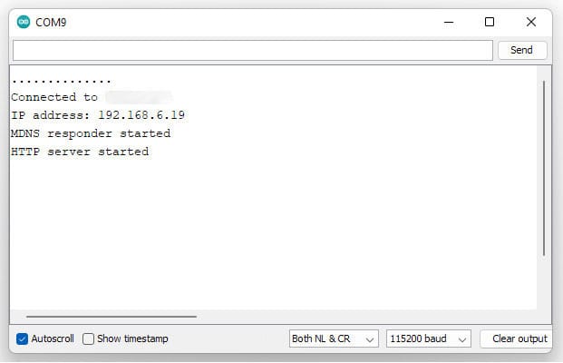
Copy the printed URL into your browser to open the generated web server page.

What’s Next?
In this project, we first became familiar with the nRF24L01 module and its various applications. Then we learned how to build a wireless connection with the nRF24L01 module and Arduino boards.
Then we learned how to create a network with nRF24L01 and upload the collected data on the web server.
To expand this project, you can do the following:
- Create multiple clients and connect them to the server. With this, you can have smart buildings.
- Instead of arduino, use ESP32 boards which can run php codes. This allows you to POST (send) data from the client to the server.
- Add different modules including relay, thermometer, gas sensor, lighting, etc. to your project.

Comment (1)
Interfacing NRF24L01 Wireless Transceiver Module with Arduino
could you add a sensor as an exemple like door open
please stiil a beginner at 72