

Overview
The multimeter is an indispensable tool for any electronics project, as it helps overcome countless challenges during project completion. This article will demonstrate how to create a cost-effective digital multimeter using an Arduino board and an OLED display. This multimeter is capable of measuring voltage, current, resistance, and capacitance. Upon completing the project, you will have your own multimeter at the lowest possible cost.
What You Will Learn
- Understand the concept of a multimeter and its importance in electronics projects
- Learn how to measure voltage accurately
- Discover the techniques for measuring current effectively
- Master the art of measuring resistance with precision
- Explore the measurement of capacitance using Arduino
- Build a Multimeter (voltmeter, ammeter, ohmmeter and capacitan) with Arduino
What Is A Multimeter?
In simple words, a multimeter is a device that converts electrical parameters such as voltage, current and so on to a language we can understand. First prototypes of this widely used device (called galvanometer) were created in 1820. Despite being only capable of measuring current, they became an essential part of any electronics projects. Knowing how to use a multimeter is essential for any electronics project
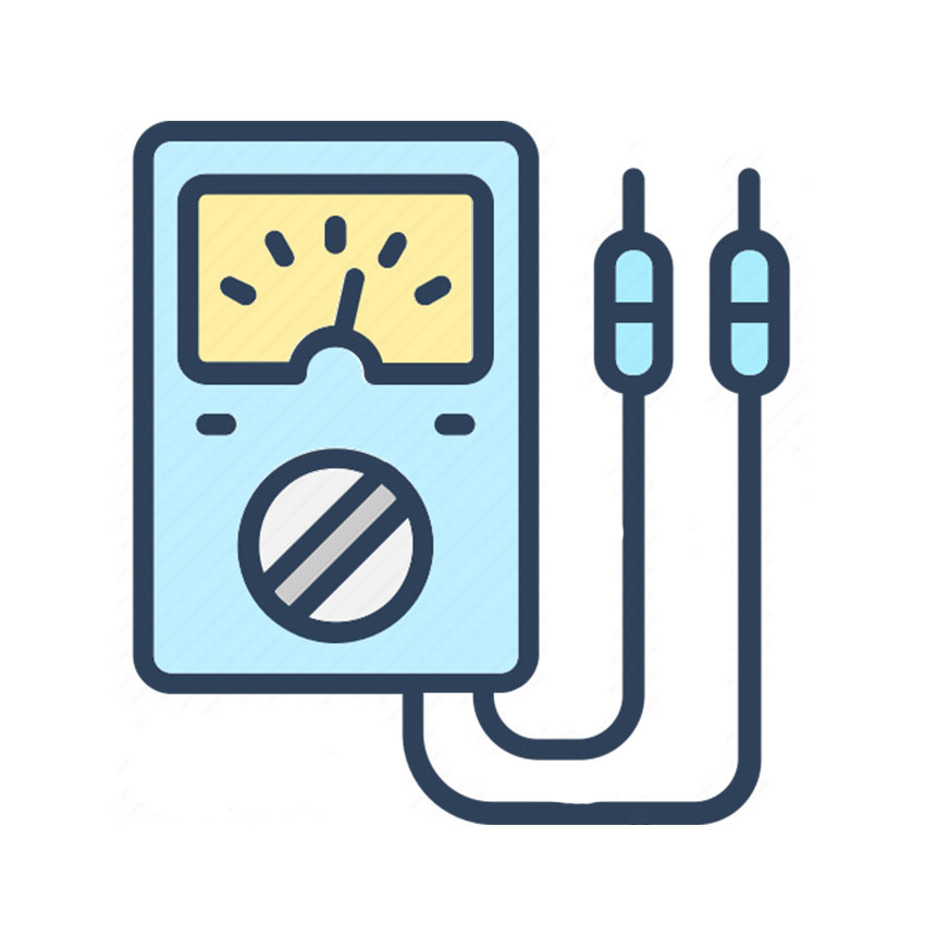
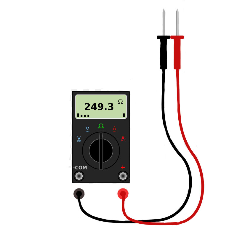
Multimeters are generally categorized as analog and digital. Analog multimeters use physical pointers to display values and are being used less and less. However, digital multimeters benefit from digital displays and are much more popular.
- An analog multimeter:
- A digital multimeter:
What Parameters Does A Multimeter Measure?
Multimeters measure various parameters. However, the most important ones are voltage, current and, resistance. Other parameters include capacitance, self-inductance, frequency, diode test, connectivity test, brightness, transistor test and, so on.
For this project, we will make a multimeter that can measure voltage, current, resistance and capacitance.
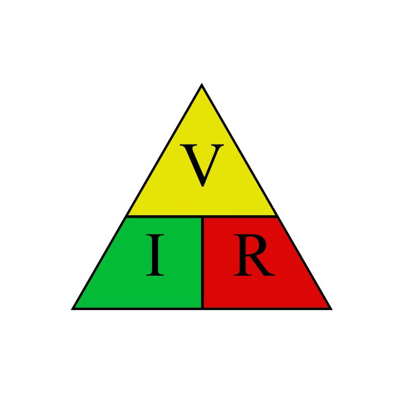
Measuring the Electrical Voltage
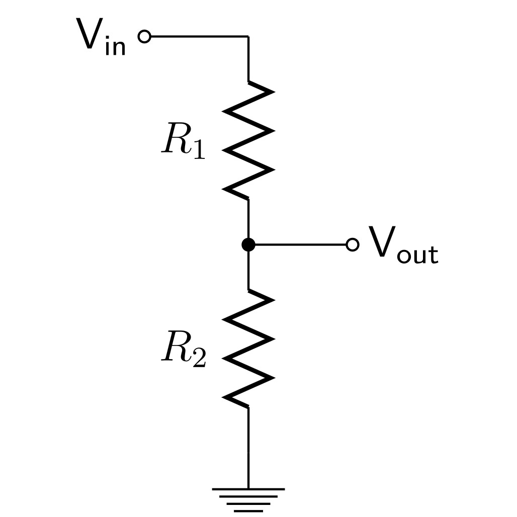
Various methods exist for measuring the voltage, such as using the hall effect, the simplest one is the voltage divider.
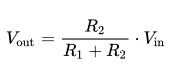
The voltage divider is a circuit that puts a fraction of the voltage between two resistors.
Measuring the Electrical Current
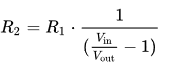
Measuring the Resistance
Measuring the Capacitance
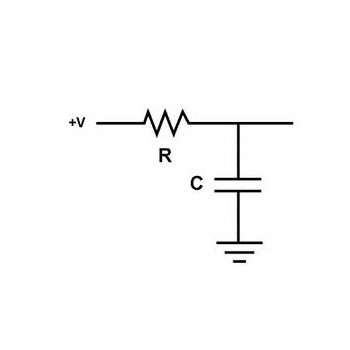
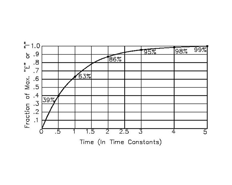
It takes a specific amount of time for the capacitor to charge to 63.2%. This is calculated using the following formula:
τ^(second)=R×C
So if we know the resistance and the time it takes for the capacitor to charge to 63.2% of its capacitance, we can calculate the capacitance.
Required Materials
Hardware Components
Software Apps
Making a Digital Multimeter Using Arduino
Step 1: Making the Voltmeter
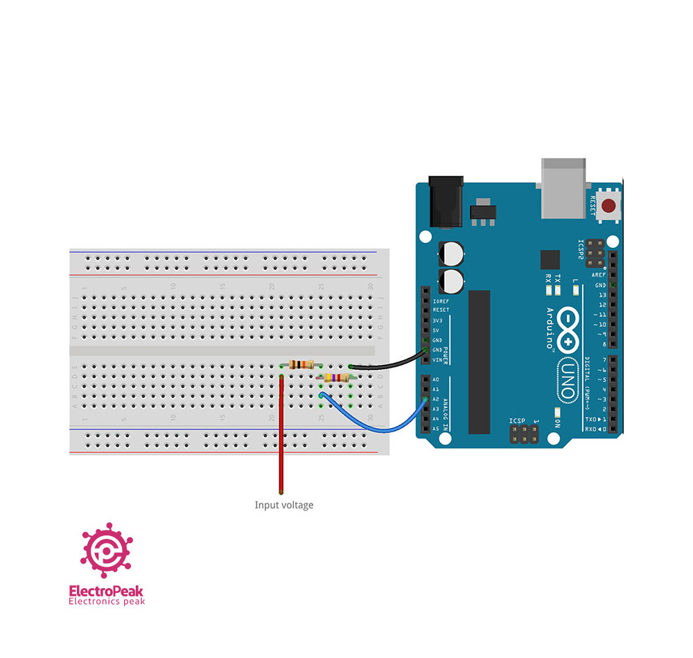
Circuit
Warning
Note
Code
/*
  Voltmeter with Arduino
   modified on 21 Jul 2019
  by Saeed Hosseini @ Electropeak
  Home
*/
const int VoltMeter = 2;
float V = 0.00;
void calculate_voltage() {
  float R1 = 10000.00;
  float R2 = 4700.00;
  float v_ref = 5.00;
  float resistor_ratio = 0.00;
  float adc_value = 0.00;
  float voltage = 0.00;
  resistor_ratio = (R2 / (R1 + R2));
  for (int i = 0; i < 20 ; i++)
  {
    adc_value = adc_value + analogRead(VoltMeter);
    delay(3);
  }
  adc_value = adc_value / 20;
  voltage = ((adc_value * v_ref) / 1024);
  V = voltage / resistor_ratio;
}
void setup() {
  Serial.begin(9600);
}
void loop() {
  calculate_voltage();
  Serial.print(V);
  Serial.println(" v");
  delay(2000);
}
Tip
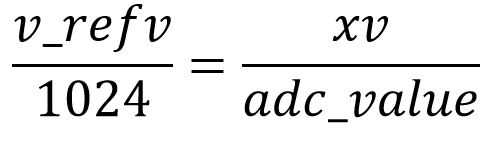
To find the voltage using the ADC unit, we use the following proportion:
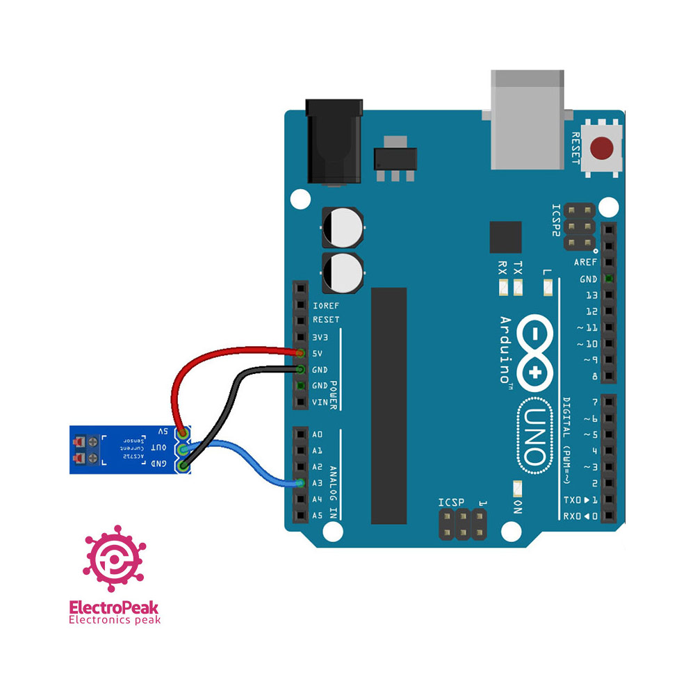
Step 2: Making the Ammeter
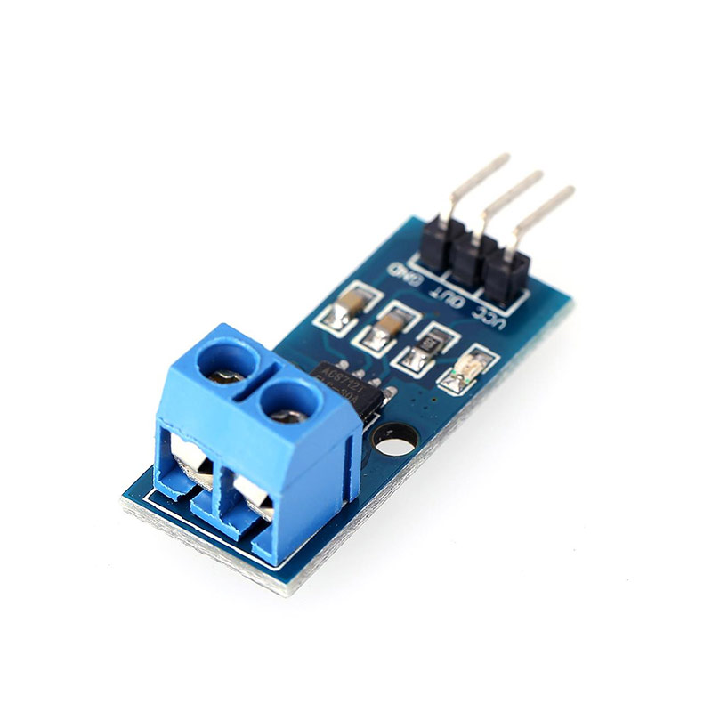
This sensor uses the hall effect to measure the current. Then it outputs a voltage proportional to the measured current, namely 185 millivolts for each amp of current.
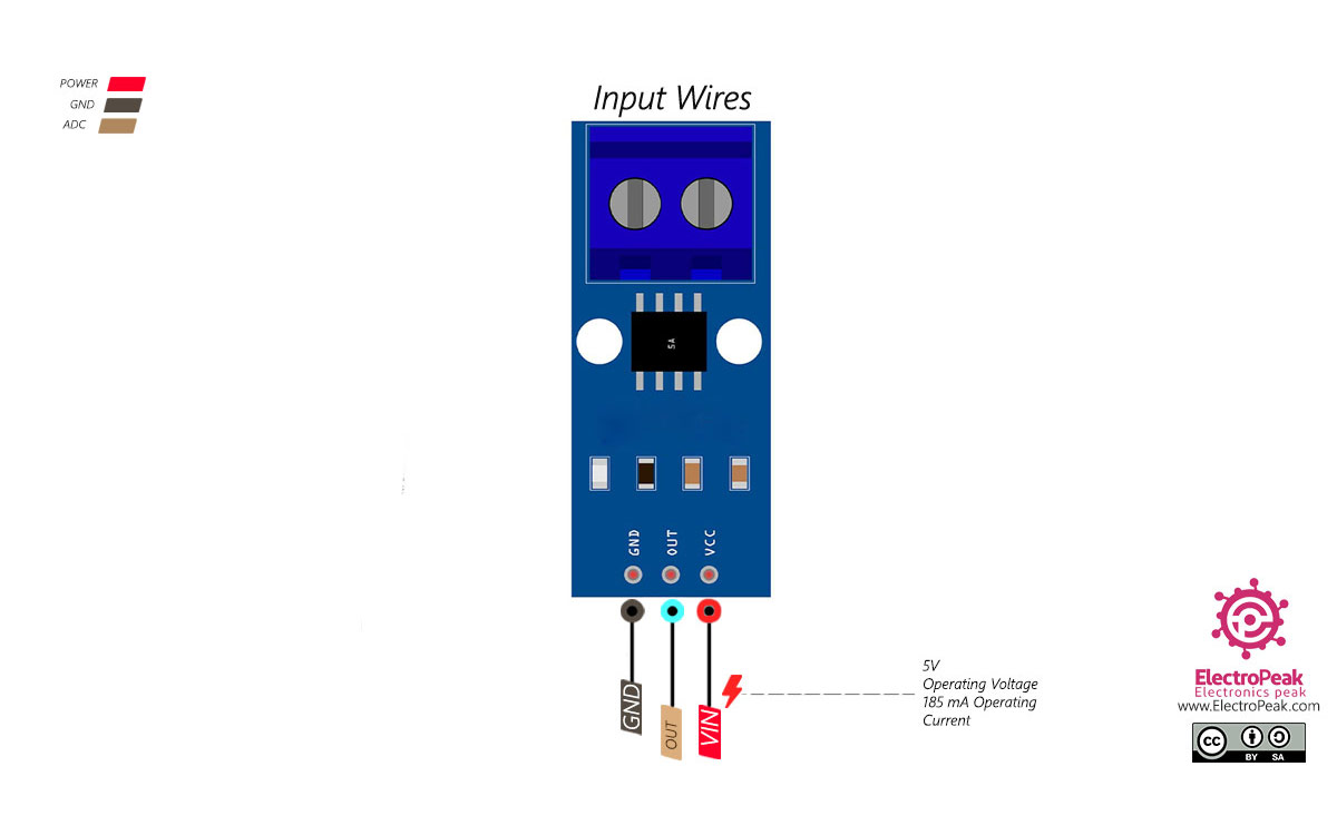
Circuit
Connect the wires according to the following diagram.
Note
Code
Upload the following code to your Arduino and view the results in the Serial Monitor window.
/*
  Ammeter with Arduino
  modified on 21 Jul 2019
  by Saeed Hosseini @ Electropeak
  Home
*/
const int Ammeter = A2;
float I = 0.00;
void calculate_current() {
  int sensitivity = 185;
  int adc_value = 0;
  float v_ref = 4.94;
  float voltage = 0.00;
  float pure_voltage = 0.00;
  float offset_voltage = 2.47;
  for (int i = 0; i < 40 ; i++)
  {
    adc_value = adc_value + analogRead(Ammeter);
    delay(2);
  }
  adc_value = adc_value / 40;
  voltage = ((adc_value * v_ref) / 1024);
  pure_voltage = voltage - offset_voltage;
 // if(pure_voltage > 0.001) pure_voltage = 0.00;
  pure_voltage = pure_voltage * 1000;
  I = pure_voltage / sensitivity;
  Serial.println(String("ADC = ") + adc_value );
  Serial.println(String("V = ") + voltage + "v");
  Serial.println(String("Pure = ") + pure_voltage + "mv");
  Serial.println(String("I = ") + I + "A");
}
void setup() {

  Serial.begin(9600);
}
void loop() {
  calculate_current();
  //Serial.println(String("I = ") + I + " mA");
  delay(2000);
}
Note
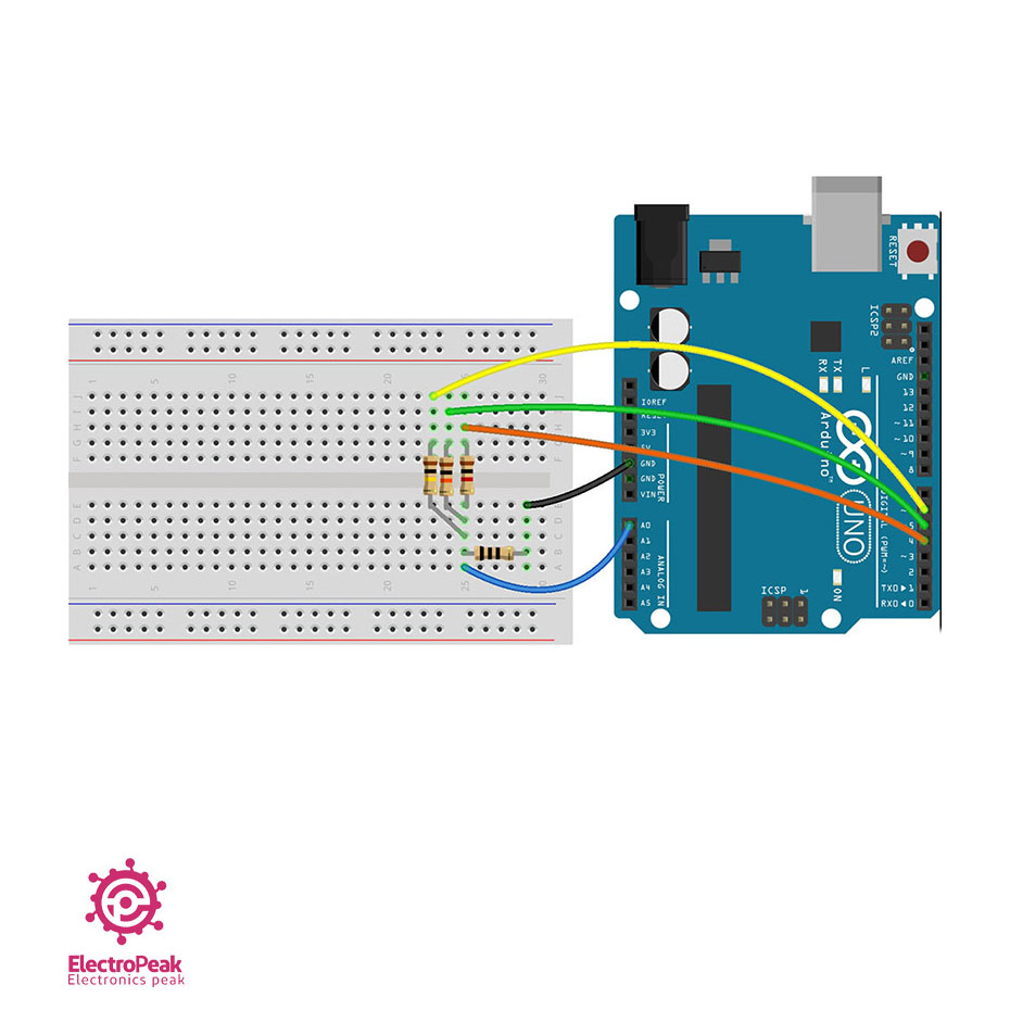
Step 3: Creating the Ohmmeter
We use the same voltage divider technique for making the ohmmeter.
The range of resistors’ values is the main issue in an ohmmeter. The farther apart resistance values of the known and unknown resistors are, the less accurate results will become. So it would be better to use several resistors to maintain smaller ranges. You can manually change the resistors using a switch or set it up automatically.
In order to automatically change the resistance range, we measure the unknown resistor one by one using the known resistors. Using the known resistors and the measured values, we calculate more accurate values for the unknown resistors.
Here we have used three ranges of 1, 10 and 100 kilo-ohms. You can make changes based on your project requirements.
Circuit
Code
Upload the following code to your Arduino and view the results in the Serial Monitor window.
/*
  Ohmmeter with Arduino - Automatic range
  modified on 21 Jul 2019
  by Saeed Hosseini @ Electropeak
  Home
*/
const int OhmMeter = 0;
const int R3 = 6;
const int R2 = 5;
const int R1 = 4;
float R = 0.00;
void calculate_resistor() {
  float v_ref = 4.94;
  float r1 = 0.00;
  float r_ref1 = 1000.00;
  float adc_value1 = 0.00;
  float voltage1 = 0.00;
  float r2 = 0.00;
  float r_ref2 = 10000.00;
  float adc_value2 = 0.00;
  float voltage2 = 0.00;
  float r3 = 0.00;
  float r_ref3 = 100000.00;
  float adc_value3 = 0.00;
  float voltage3 = 0.00;
  pinMode(R1, OUTPUT);
  pinMode(R2, INPUT);
  pinMode(R3, INPUT);
  digitalWrite(R1, HIGH);
  for (int i = 0; i < 20 ; i++)
  {
    adc_value1 = adc_value1 + analogRead(OhmMeter);
    delay(3);
  }

  adc_value1 = adc_value1 / 20;

  if (adc_value1 < 1022.90)
  {
    voltage1 = ((adc_value1 * v_ref) / 1024);
    r1 = (voltage1 * r_ref1) / (v_ref - voltage1);
  }
  pinMode(R1, INPUT);
  pinMode(R2, OUTPUT);
  pinMode(R3, INPUT);
  digitalWrite(R2, HIGH);
  for (int i = 0; i < 20 ; i++)
  {
    adc_value2 = adc_value2 + analogRead(OhmMeter);
    delay(3);
  }
  adc_value2 = adc_value2 / 20;
  if (adc_value2 < 1022.90)
  {
    voltage2 = ((adc_value2 * v_ref) / 1024);

    r2 = (voltage2 * r_ref2) / (v_ref - voltage2);
  }
  pinMode(R1, INPUT);
  pinMode(R2, INPUT);
  pinMode(R3, OUTPUT);
  digitalWrite(R3, HIGH);
  for (int i = 0; i < 20 ; i++)
  {
    adc_value3 = adc_value3 + analogRead(OhmMeter);
    delay(3);
  }
  adc_value3 = adc_value3 / 20;
  if (adc_value3 < 1022.90)
  {
    voltage3 = ((adc_value3 * v_ref) / 1024);
    r3 = (voltage3 * r_ref3) / (v_ref - voltage2);
  }
  r1 = r1 / 1000;

  r2 = r2 / 1000;

  r3 = r3 / 1000;
  if (r1 < 2 && r2 < 101 && r3 < 1001) R = r1*1000;
  else if (r1 > 2 && r2 < 101 && r3 < 1001) R = r2;
  else if (r1 > 2 && r2 > 101 && r3 < 2000) R = r3;
  else R = 0.00;
  Serial.print("R = ");

  Serial.println(R, 2);
}
void setup() {

  Serial.begin(9600);
}
void loop() {
  calculate_resistor();
  Serial.println("_________________________________________");

  delay(2500);
}
Note
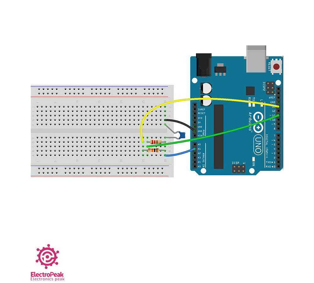
Step 4: Building the Capacitance Meter
Circuit
Here we used a 10 kilo-ohm resistor to charge the capacitor and a 220-ohm resistor for discharge.
Connect the wires according to the following diagram.
Code
Upload the following code to your Arduino and view the results in the Serial Monitor window.
/*
  Capacitance meter with Arduino
  modified on 21 Jul 2019
  by Saeed Hosseini @ Electropeak
  base on: https://www.arduino.cc/en/Tutorial/CapacitanceMeter
  Home
*/
const int CapacitancMeter = 1;
const int ChargePin = 13;
const int DischargePin = 11;
float C = 0.00;
void calculate_capacitance() {
  unsigned long start_time;
  unsigned long elapsed_time;
  float microFarads;
  float nanoFarads;
  float r_ref = 10000.00;
  digitalWrite(ChargePin, HIGH);
  start_time = millis();
  while (analogRead(CapacitancMeter) < 648) {}
  elapsed_time = millis() - start_time;
  microFarads = ((float)elapsed_time / r_ref) * 1000;
  if (microFarads > 1)
  {
    C = microFarads;
  }

  else
  {
    nanoFarads = microFarads * 1000.0;
    C = nanoFarads;
  }
  digitalWrite(ChargePin, LOW);
  pinMode(DischargePin, OUTPUT);
  digitalWrite(DischargePin, LOW);
  while (analogRead(CapacitancMeter) > 0) {}
  pinMode(DischargePin, INPUT);
}

void setup() {
  Serial.begin(9600);
  pinMode(ChargePin, OUTPUT);

  digitalWrite(ChargePin, LOW);
}
void loop() {
  calculate_capacitance();
  Serial.println(C);

  delay(2000);
}
The measurement algorithm is as follows:
- Start charging the capacitor and registering the starting time using millis() command
- Continue charging up to 63.2% of the total capacitance of the capacitor (equal to 648 in ADC)
- Recording the elapsed time until reaching 63.2% charge
- Calculating the capacitance using the time constant formula, knowing the resistance and time
- Full discharge of the capacitor
Note
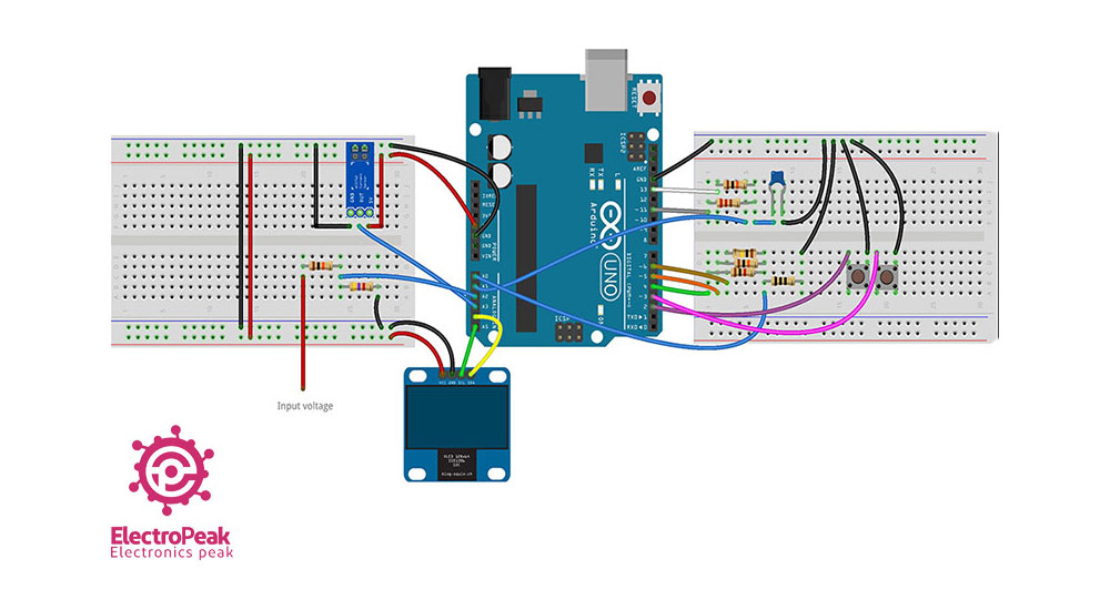
Step 5: Wrapping it Up And Adding a Display
CIrcuit
Code
Upload the following code to your Arduino and view the results in the Serial Monitor window.
/*
  Digital Multimeter with Arduino and OLED
  modified on 21 Jul 2019
  by Saeed Hosseini @ Electropeak
  Home
*/
#include <Wire.h>
#include <Adafruit_GFX.h>
#include <Adafruit_SSD1306.h>
#include "logo.h"
#define SCREEN_WIDTH 128
#define SCREEN_HEIGHT 32
#define OLED_RESET -1
Adafruit_SSD1306 display(SCREEN_WIDTH, SCREEN_HEIGHT, &Wire, OLED_RESET);
const int select_button = 2;
const int right_button = 3;
const int OhmMeter = A0;
const int CapacitancMeter = A1;
const int VoltMeter = A2;
const int Ammeter = A3;
const int R3 = 6;
const int R2 = 5;
const int R1 = 4;
const int ChargePin = 13;
const int DischargePin = 11;
boolean is_select = false;
int navigator = 0;
int flag = 0;
float R = 0.00;
float V = 0.00;
float I = 0.00;
float C = 0.00;
boolean nano = false;
boolean kilo = false;
boolean mili = false;
void OLED_init() {
  if (!display.begin(SSD1306_SWITCHCAPVCC, 0x3C))
  {
    Serial.println(F("SSD1306 allocation failed"));
    for (;;);
  }
  display.clearDisplay();
  diplay_logo(15, 3, Electropeak, F_LOGO_WIDTH, F_LOGO_HEIGHT);
  display.display();
  delay(2000);
  display_clear();
}
void display_clear() {
  display.clearDisplay();
  display.display();
}
void diplay_logo(int x, int y, const uint8_t *bitmap, int w, int h) {
  display.drawBitmap(x, y, bitmap, w, h, WHITE);
}
void display_text(int sz, int x, int y, String str) {
  display.setTextSize(sz);
  display.setTextColor(WHITE);
  display.setCursor(x, y);
  display.println(str);
}
void display_number(int sz, int x, int y, double num) {
  display.setTextSize(sz);
  display.setTextColor(WHITE);
  display.setCursor(x, y);
  display.println(num);
}
void calculate_resistor() {
  float v_ref = 4.94;
  float r1 = 0.00;
  float r_ref1 = 1000.00;
  float adc_value1 = 0.00;
  float voltage1 = 0.00;
  float r2 = 0.00;
  float r_ref2 = 10000.00;
  float adc_value2 = 0.00;
  float voltage2 = 0.00;
  float r3 = 0.00;
  float r_ref3 = 100000.00;
  float adc_value3 = 0.00;
  float voltage3 = 0.00;
  pinMode(R1, OUTPUT);
  pinMode(R2, INPUT);
  pinMode(R3, INPUT);
  digitalWrite(R1, HIGH);
  for (int i = 0; i < 20 ; i++)
  {

    adc_value1 = adc_value1 + analogRead(OhmMeter);
    delay(3);
  }
  adc_value1 = adc_value1 / 20;

  if (adc_value1 < 1022.90)

  {

    voltage1 = ((adc_value1 * v_ref) / 1024);

    r1 = (voltage1 * r_ref1) / (v_ref - voltage1);

  }


  pinMode(R1, INPUT);

  pinMode(R2, OUTPUT);

  pinMode(R3, INPUT);

  digitalWrite(R2, HIGH);

  for (int i = 0; i < 20 ; i++)

  {

    adc_value2 = adc_value2 + analogRead(OhmMeter);

    delay(3);

  }

  adc_value2 = adc_value2 / 20;

  if (adc_value2 < 1022.90)

  {

    voltage2 = ((adc_value2 * v_ref) / 1024);

    r2 = (voltage2 * r_ref2) / (v_ref - voltage2);

  }


  pinMode(R1, INPUT);

  pinMode(R2, INPUT);

  pinMode(R3, OUTPUT);

  digitalWrite(R3, HIGH);

  for (int i = 0; i < 20 ; i++)

  {

    adc_value3 = adc_value3 + analogRead(OhmMeter);

    delay(3);

  }

  adc_value3 = adc_value3 / 20;

  if (adc_value3 < 1022.90)

  {

    voltage3 = ((adc_value3 * v_ref) / 1024);

    r3 = (voltage3 * r_ref3) / (v_ref - voltage2);

  }


  r1 = r1 / 1000;

  r2 = r2 / 1000;

  r3 = r3 / 1000;


  if (r1 < 2 && r2 < 101 && r3 < 1001) R = r1 * 1000;

  else if (r1 > 2 && r2 < 101 && r3 < 1001) R = r2;

  else if (r1 > 2 && r2 > 101 && r3 < 2000) R = r3;

  else R = 0.00;


  if (R < 1)

  {

    R = R * 1000;

    kilo = false;

  }

  else

  {

    kilo = true;

  }


}


void calculate_capacitance() {

  unsigned long start_time;

  unsigned long elapsed_time;

  float microFarads;

  float nanoFarads;

  float r_ref = 10000.00;


  digitalWrite(ChargePin, HIGH);

  start_time = millis();


  while (analogRead(CapacitancMeter) < 648) {}


  elapsed_time = millis() - start_time;


  microFarads = ((float)elapsed_time / r_ref) * 1000;

  if (microFarads > 1)

  {

    C = microFarads;

    nano = false;

  }

  else

  {

    nanoFarads = microFarads * 1000.0;

    C = nanoFarads;

    nano = true;

  }


  digitalWrite(ChargePin, LOW);

  pinMode(DischargePin, OUTPUT);

  digitalWrite(DischargePin, LOW);

  while (analogRead(CapacitancMeter) > 0) {}

  pinMode(DischargePin, INPUT);


}


void calculate_voltage() {

  float R1 = 10000.00;

  float R2 = 4700.00;

  float v_ref = 5.00;

  float resistor_ratio = 0.00;

  float adc_value = 0.00;

  float voltage = 0.00;


  resistor_ratio = (R2 / (R1 + R2));

  for (int i = 0; i < 20 ; i++)

  {

    adc_value = adc_value + analogRead(VoltMeter);

    delay(3);

  }

  adc_value = adc_value / 20;

  voltage = ((adc_value * v_ref) / 1024);


  V = voltage / resistor_ratio;

}


void calculate_current() {

  int sensitivity = 185;

  int adc_value = 0;

  float v_ref = 4.94;

  float voltage = 0.00;

  float pure_voltage = 0.00;

  float offset_voltage = 2.47;


  for (int i = 0; i < 40 ; i++)

  {

    adc_value = adc_value + analogRead(Ammeter);

    delay(2);

  }

  adc_value = adc_value / 40;

  voltage = ((adc_value * v_ref) / 1024);

  pure_voltage = voltage - offset_voltage;

  pure_voltage = pure_voltage * 1000;

  I = pure_voltage / sensitivity;


  if (I < 1)

  {

    I = I * 1000;

    mili = true;

  }

  else

  {

    mili = false;

  }

}
void setup() {

  Serial.begin(9600);

  OLED_init();

  pinMode(right_button, INPUT_PULLUP);

  pinMode(select_button, INPUT_PULLUP);

  pinMode(ChargePin, OUTPUT);

  digitalWrite(ChargePin, LOW);
}

void loop() {

  if (digitalRead(right_button) == 0)
  {

    navigator++;

    while (digitalRead(right_button) == 0);

    delay(5);

    if (navigator > 3) navigator = 0;

    Serial.println(navigator);

  }

  if ( digitalRead(select_button) == 0)

  {

    is_select = true;

    while ( digitalRead(select_button) == 0);

  }

  if (navigator == 0)

  {

    display.clearDisplay();

    diplay_logo(0, 0, RightArrow, F_LOGO_WIDTH, F_LOGO_HEIGHT);

    display_text(2, 17, 8, "Resistor");

    display.display();

    while (is_select)

    {

      display.clearDisplay();

      display_text(1, 0, 0, "Resistor");

      display_text(2, 12, 8, "R=");

      display_number(2, 42, 8, R);

      if (kilo) display_text(1, 115, 15, "k");

      display.display();

      calculate_resistor();

      if ( digitalRead(select_button) == 0)

      {

        is_select = false;

        while ( digitalRead(select_button) == 0);

      }

    }


  }

  if (navigator == 1)

  {

    display.clearDisplay();

    diplay_logo(0, 0, BothArrow, F_LOGO_WIDTH, F_LOGO_HEIGHT);

    display_text(2, 17, 8, "Voltage");

    display.display();

    while (is_select)

    {

      display.clearDisplay();

      display_text(1, 0, 0, "Voltage");

      display_text(2, 12, 8, "V=");

      display_number(2, 42, 8, V);

      display_text(1, 115, 15, "v");

      display.display();

      calculate_voltage();

      if ( digitalRead(select_button) == 0)

      {

        is_select = false;

        while ( digitalRead(select_button) == 0);

      }

    }

  }

  if (navigator == 2)

  {

    display.clearDisplay();

    diplay_logo(0, 0, BothArrow, F_LOGO_WIDTH, F_LOGO_HEIGHT);

    display_text(2, 17, 8, "Current");

    display.display();

    while (is_select)

    {

      display.clearDisplay();

      display_text(1, 0, 0, "Current");

      display_text(2, 12, 8, "I=");

      display_number(2, 42, 8, I);

      if (mili) display_text(1, 115, 15, "mA");

      if (!mili) display_text(1, 115, 15, "A");

      display.display();

      calculate_current();

      if ( digitalRead(select_button) == 0)

      {

        is_select = false;

        while ( digitalRead(select_button) == 0);

      }

    }

  }

  if (navigator == 3)

  {

    display.clearDisplay();

    diplay_logo(0, 0, LeftArrow, F_LOGO_WIDTH, F_LOGO_HEIGHT);

    display_text(2, 12, 8, "Capacitor");

    display.display();

    while (is_select)

    {

      display.clearDisplay();

      display_text(1, 0, 0, "Capacitor");

      display_text(2, 12, 8, "C=");

      display_number(2, 42, 8, C);

      if (nano) display_text(1, 115, 22, "nF");

      if (!nano) display_text(1, 115, 22, "uF");

      display.display();

      calculate_capacitance();

      if ( digitalRead(select_button) == 0)

      {

        is_select = false;

        while ( digitalRead(select_button) == 0);

      }

    }

  }

}

Success
What’s Next?
• Add the automatic range switch for capacitance measurement
• Ability to test connectivity to your multimeter
Explore more exciting electronics projects and expand your skills in the fascinating world of electronics. Stay tuned for more guides and tutorials at Your Electronics Guide.

Comments (71)
Hello. thank you for this Article. it will surely be a great help in building our own multimeter project. I hope you’ll response in my question while building this kind of project. Thanks again!
Hi. We are very glad to hear this article was useful for you.
hi there, just wanna ask some question. how can i combine all the codes?
Hi.
Actually you don’t need to compile all the codes to make the digital multimeter. Separate parts of the digital multimeter are explained in steps 1 to 4. And in step 5, all previous steps are wrapped up in a single circuit and code. So if your question is how you can make a complete digital multimeter -and not just an Ohmmeter or Ammeter-, you can do that by just following the code and circuit of the step 5.
hehe you’re right, its in step 5. thanks a lot.
what should be the right thing to do with the logo.h file? i’ve copied it to the folder where my code is located but it keeps showing an error “logo.h: no such file or directory”.
You should copy it to the folder where your .ino file is located, meaning that logo.h and your .ino file must be in the same folder. In that way when you open the .ino file, logo.h will also appear in a tab next to it. And then there shouldn’t be any problem.
thank you. it finally works! thanks for this article!
Where to connect the inputs for resistance and capacitance?
For measuring the resistance, connect the resistor to the A0 and GND pins of your Arduino Board. And for capacitance, you need to connect the capacitor to pins A1 and GND.
excuse me guys but i dont know how to measure the current?? so can you tell me where to connect the inputs of th curreny?
Hi,
To measure the current, you need to use the AC712 sensor. It is well explained in the “Step 2: Making the Ammeter” section. This sensor has 3 pins, 2 for the power supply -GND and VCC- and the other one “OUT” which is the output pin of the sensor and needs to be connected to an analog pin of Arduino Board -A3 in our case-. Other necessary notes are also included in article.
Hello,
I’m trying assembly this circuit on tinkercad, but I can’t find the part (0.96″ I2C OLED Display Module)
The picture that you shared on step 5 is about tinkercad or did you use another software?
Can you please help me?
Hello Luis,
The picture in step 5 is actually made using a combination of the fritzing and photoshop software programs just to show how the wiring should be. And If you want to use Tinkercad for modelling the circuit, the following link might be helpful. “https://www.tinkercad.com/things/2EKXoCr8iki-096-128×64-oled-display”
Electropeak in making the capacitance
What is the name of the Blue component used with the resistors
That’s the capacitor that we want to measure the value of.
What if I want to add a chargeable battery to the circuit how can I go about it.
Secondly please where would my red and black probes be fixed on the board.
To add a chargeable battery -or any other type of battery-, you can just connect the positive terminal of the battery to the VIN pin and the negative terminal to the GND pin of the Arduino board. And you don’t need to make any other changes to the rest of the circuit.
And about the probes, the black one can be fixed at the GND pin. But where the red one should be fixed at depends on what electrical component you want to measure the value of. For example, to measure the value of a resistor or a capacitor, you should fix the red probe at A0 or A1 pin of your Arduino board respectively.
Thank you very much
This website is very helpful
but can I ask please
What if i did not get the AC712 5A Current Sensor is there any alternatives
You’re quite welcome. So glad the tutorials have been useful for you.
About the ACS712 current sensor, you can replace that with any other current sensor that has an analog output voltage ranging 0 to 5 volts. Then you need to change the code according to the current to voltage formula of the sensor you’re using.
Thank you for this. I’m currently doing a similar project
Right now I’m searching for the best way to adapt main voltage (220 VAC) signal into an analog input that doesn’t fry up my arduino. A voltage divider is out of question and I don’t seem to find a suitable transformer for the job of just measuring.. Any suggestions?
Hello.
You’re welcome.
There are actually a handful of modules that can convert high voltage AC to a DC voltage that can be read by any of your Arduino analog pins. ZMPT101B voltage sensor is one of these modules. You can also find a good tutorial of this sensor in our website. Here’s the link: “https://electropeak.com/learn/interfacing-zmpt101b-voltage-sensor-with-arduino/”
could not convert display.Adafruit_SSD1306 from void to bool
That is what my code( in the Arduino ide) is saying
Any help please ?????
Which line of the code is the error for? There might also have been some mistakes made while copying the code. So, please double check it and make sure that nothing has gone wrong in the process of copying the code and taking it to your Aduino IDE. Then, if the error still persisted and didn’t go away, say which line of the code exactly the error is about.
Electropeak thank you very much I am done with the project but I am having some incorrect readings, the resistor is not measuring and before I test for anything the multimeter just keep reading Like when it is supposed to be 0.00 it would keep reading randomly. Any help please
Your problem can be actually related to the tolerance of the components in your circuit. And generally, a little inaccuracy is acceptable.
Hi,
Do you have an idea how to protect the meter be mistested or misseted, say use a R gear to measure a Voltage by mistake?
Thanks
Adam
Hi,
Unfortunately, I couldn’t fully understand your point. But if you mean how you could calibrate the multimeter so that the voltage is never measured wrongly, you can do as following: You can add this capability to your multimeter by replacing the R2 resistor in the “Measuring the Electrical Voltage” circuit with a multi-turn potentiometer. So, this way, whenever you feel your multimeter is out of calibration, you can adjust the value of the resistor and calibrate the multimeter.
Hey there would you have an idea on how to measure AC voltage?
Yes, there are some modules especially designed for that. For example, the ZMPT101B sensor can be used to measure AC voltages up to 250 volts. You can check the following tutorial for more details on how you can use this module:
“https://electropeak.com/learn/interfacing-zmpt101b-voltage-sensor-with-arduino/”
Hello, i have been trying to run the code for the multimeter but it keeps saying, no matching function for call to ‘Adafruit_SSD1306::Adafruit_SSD1306(int, int, TwoWire*, int)’. How can i solve this error?
Hi…
You probably don’t have the right SSD1306 library installed on your Arduino IDE. To install the appropriate library, open Arduino IDE, go to “Tools → Manage Libraries” and search for SSD1306. Look for “Adafruit SSD1306” and install it. Or update it if it’s already installed. That would solve your problem.
Hi,
thank you for your wonderful work.
I did everything and it went very well, but I have a question, what do I need to change in the program if I take an HD44780 Display instead of the Oled display.
Hi. You’re welcome.
If you want to change the display to HD44780, first, note that it’s no easy job. You might not have enough pins to interface it with Arduino Uno, and also you can’t easily display animations on it. But, if you want to replace the OLED display with an HD44780 one, you will need to change all lines that are related to display and replace them with appropriate code for HD33780 display. The following tutorial shows how you can interface an HD44780 display with an Arduino board and use it.
https://electropeak.com/learn/interfacing-character-lcd-display-modules-with-arduino/
Hi, im willing to make this multimeter but I can’t find the “0.96” Resistor 220 ” could someone send me a link so that I can buy it. Also if possible to someone to send me a picture of the final result of the mutlimeter to [email protected] fast as possible. It would help me a lot.
Thanks
Hi.
It’s just a simple 220-ohm resistor. “0.96” was just a typing mistake.
Good project!! With nothing connected to the “R” input, it reads R=0.00 -it should read infinity. Also when measuring resistance below 1k, the “K” remains showing on display.
Hi. Thanks for your feedback! We’ll look into that.
Hi there ,,,thank you for your effort guys but I got a simple question …. i’ve connected all the components in the circuit above with applying the code you guys put …. but its never measuring values of R and C so do have any assumption where the problem is ,,,,and can you explain how can i use it to measure the voltage because i cant get it
Thank you in advance
Hi,
An important point to consider when making such big circuits with a lot of components is to do it step by step. So, instead of connecting all components at once and applying the final code, try to make the smaller circuits and use the codes corresponding to them. That way, you can debug your problem more easily.
Thanks for everything good tutorial
I want to ask about something. I want to add many thing to this project by (software) but I do not know the code. I want to add the following:
DC (Power and Energy)
AC (Voltage , Current , ohm , Capacitance , Power and Energy)
Note: I want it by software and I want as an addition to the main project not individual
If you can help me with that I will appreciate that
you can contact me on my email
Hi.
Unfortunately, we cannot accept projects. But if you ever decide to do those things you want on your own, we will be so happy to help.
Please I have another question if I want to add DC (Power and Energy)
What should I do how can I calculate P=VI and E=Pt by coding
Hi.
Well, you can calculate the voltage and current (“V” and “I”) using the code in this tutorial. And by having “V” and “I”, you can easily declare an integer variable named “P” and calculate the power using formula “P=VI”.
And you can do the same for the energy. Declare an integer variable and name it “E”, then calculate the energy using the formula “E=Pt”. The variable “t” can be chosen arbitrarily.
You can study the link below for more notes on how to write your code, or consult a programmer.
https://www.programmingelectronics.com/tutorial-3-arduino-ide-and-sketch-overview/
thank you and can I contact you by email or whatsapp ?
Unfortunately not. You can just ask your questions here in the comments.
Hello, thanks for the great project. I only have one problem, I can’t find the OLED anywhere near me and I can only find LCDs can that work? and do you have any Idea how to edit the code to make it work around using an lcd for an output?
Hi,
LCDs can work, too. But there would probably be a lot of change in the code required to make it work. The tutorials below might help you.
https://electropeak.com/learn/interfacing-i2c-16×2-character-lcd-1602-display-module-with-arduino/
https://electropeak.com/learn/interfacing-character-lcd-display-modules-with-arduino/
https://electropeak.com/learn/using-1602-character-lcd-keypad-shield-arduino/
Hello , i have a question , why do you divide by 20 the adc_value in the first step ? “adc_value = adc_value / 20” ? is it because u increment until it’s 20 for i ?
Yes, exactly. It is mainly done to reduce the effect of noise in our measurements.
I am getting a lot of errors in it like Adafruit_GFX.h , Adafruit_SSD1306.h No such file or directory etc. Can anyone kindly help me with making this project?
Hi, I have a question. What changes do I have to do if I want the following ranges of readings from my multimeter:
DC Voltage [100mV – 20V]
DC Current [10mA – 20mA]
Hi
you can use c code that has been written on step2, but note that maximum measuring voltage for ACS712 is 15vDC.
It is so easy to estimate measuring range with a simple propotion between reference voltage and sensivity
for example for 3.3V and 185mv/A(this is Sensivity of ACS712) and 10bit ADC resolution(1023) the result is 57
so for 0.5A = 500mA = 28.5 that you can see in output
And also please tell if this whole process can also meaure AC voltage and current or not??
Yes.
you can use it for this goal.
what is the function of logo.h?
Hi.
logo.h is a library that has several functions to use.
please i want to know codes in Voltmeter , why adc_value divided by 20 ? i dont get it.
Hi dear
if you note to above of adc_value = adc_value / 20; line
you see the for loop with 20 step that read the analog value and plus the Previous and next value.
actually with need to get avarge from 20 cases to get more accurate value.
Greetings
Mehran Maleki
Looking at your project I find it very interesting to try and make one. But I am wondering how I can connect a battery to the circuit for the meter to be portable?
Hi Fedrick
You should use the following device: 5v-1a-power-bank-charger-lithium-battery
When you get the device, you need to connect the battery to this device, and then this device to Arduino.
what changes do i need to make if i want to send the data to my cloud channel in thingspeak instead of displaying it on display board?
Hi Crimson
You should use ESP32 as the microcontroller instead of Arduino Uno. To send data to your cloud channel, you can read the related tutorials on Internet.
I have connected same circuit but nothing is visible on OLED display ,what’s wrong with it???
Hi Navin,
Use an I2C scanner to check your wiring and ensure that the OLED is connected correctly. Additionally, you can try running the OLED example separately to verify whether the OLED is functioning correctly.
can it be used to measuring negative voltage and mV range?
Hi Hukoro,
No, for reading voltage, we use a voltage divider that can read greater than 0 volts.
To measure negative voltage, you might need an external ADC module that supports both positive and negative voltages. Ensure that you provide a suitable negative voltage source for the ADC module.
Alternatively, you can use a full bridge rectifier to convert all voltages to positive values. Then, use an op-amp at the input to detect if the original voltage was positive or negative. Note that this method only works for voltages greater than 0.7 volts (diode forward voltage).
Hello,
can you describe this piece of your code more in Detail please?
I have problems to understand, why you use this condition:
if (r1 < 2 && r2 < 101 && r3 2 && r2 < 101 && r3 2 && r2 > 101 && r3 < 2000) R = r3;
else R = 0.00;
Why you dont use r1 < 11? Why you use r1 < 2?
Because, when i want to use another resistance for lower measures, for example r0 = 150 Ohms, what is the condition?
Is it
r0 < 0.1 && r1 < 2 && r2 < 101 && r3 < 1001 R = r0*10000 ??
best regards
Hello,
In this line, we are measuring the values obtained by the resistive dividers R1_ref, R2_ref, and R3_ref. If the measured resistance is less than 2 kilo-ohms, it uses the R1_ref reference resistor path for measuring the analog value because the sensitivity of the microcontroller in measuring this resistance through this resistor is higher than with R2_ref or R3_ref. Similarly, for measuring resistances higher than 2 kilo-ohms and less than 100 kilo-ohms, the R2_ref resistor circuit is used for measurement.
The values set for comparison here are approximate. You can measure resistances up to 5 kilo-ohms with adequate accuracy using the R2_ref reference resistor circuit. The maximum values specified for measurement through the R2_ref and R3_ref paths (100 and 1000 kilo-ohms) are intended solely to extend the measurement range. If you want to achieve proper measurement accuracy, the resistance you wish to measure should be between one-fifth and five times the value of the reference resistor.
Hello,
i have another question.
Can i use an external 5V power source with your design and external reference ( analogReference(EXTERNAL); ), how must i connect the wires?
You use the digital pins as some kind of switches or voltage sources, right? But i want to use a external 5V power source for better results.
greetings
For your second question:
Yes, you can use the V_ref pin (the reference voltage pin) on the Arduino UNO to provide an external reference voltage for measuring analog voltages. By default, the Arduino UNO uses the 5V pin as the reference voltage for analog-to-digital conversion (ADC). However, you can provide an external reference voltage to improve the accuracy and range of your analog measurements, especially if you need to measure voltages in a different range. Wiring is similar to what is on this page.