
Product added to cart

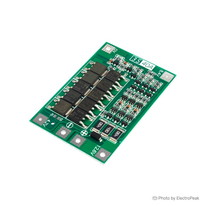
3S Lithium Battery Charging Protection Board - 11.1V, 40A
$0.7500
In stock
SKU
BAT-03-045
Volume discounts:
- +50 4 % $0.7200
- +100 5 % $0.7100
- +300 8 % $0.6900
- +500 9 % $0.6800
- +1000 12 % $0.6600
Ships in 2-3 business days, then:
Free delivery in 12-15 days by Tracked Economic Shipping on orders over $100.
Free delivery in 7-10 days by Express Shipping on orders over $300.
More shipping info

Shop with confidence Learn More
 3S Lithium Battery Charging Protection Board - 11.1V, 25A Previous
3S BMS 11.1V 40A Protection Board Review
This board protects and passively balances a 3S Li-ion or Li-Po battery pack during charging and use. It provides fail-safe cutoffs for overcharge, over-discharge, and short circuits, making it suitable for builders constructing or maintaining 11.1V nominal lithium battery assemblies. This module is strictly a protective circuit, not a complete charging solution. A separate suitable charging source is required to regulate current and voltage safely into the pack.
The module is intended for builders with the tools and experience to assemble, inspect, wire, and meter lithium battery packs. One fundamental limitation should be clear before you design it into hardware: this product has no supplied manufacturer identity, revision-controlled documentation, or verified thermal-performance testing. See other battery management system modules if your build requires documented enterprise traceability or active bus communication.
Specifications of 3S Lithium Battery Charging Protection Board - 11.1V, 40A
- Charging Voltage: DC 12.6V to 13.6V
- Continuous Charging Current: Up to 20A
- Continuous Discharge Current: Up to 40A
- Nominal Cell Voltage: 3.7V
- Fully Charged Voltage: 4.2V
- Battery Type: 3S Li-ion or Li-Po battery packs
- Compatible Battery Types: 18650
- Compatible Battery Types: 26650
- Compatible Battery Types: Lithium Polymer
- Power Handling: Up to 135W
- Board Size (Balance Version): 61x41x4mm
- Board Size (Enhanced Version): 55x41x4mm
- Balancing Current: Up to 60mA per cell
- Operating Temperature: -20°C to +60°C
3S BMS 11.1V 40A Specifications Explained
A 3S configuration has three cell groups connected in series. Each group can contain a single cell or multiple matched cells wired in parallel, such as 3S2P or 3S3P, to increase total runtime. The pack is nominally 11.1V with standard 3.7V chemistry, while three cells in series reach 12.6V when fully charged to 4.2V per cell. For systems requiring higher operating voltages, a four-cell series layout with the 4S 16.8V 40A BMS Board provides a dedicated 16.8V battery-protection path.
Standard cylindrical formats such as 18650 and 26650, along with flat pouch Lithium Polymer packs, are compatible only when they strictly follow standard 3.7V nominal and 4.2V cutoff thresholds. Builders assembling cylindrical configurations often use cells such as the UItraFire 18650 Lithium Battery 6800mAh. Every individual cell must still be thoroughly verified for authentic capacity, internal-resistance matching, and adequate discharge current before assembly.
| Specification | Listed Value | Why It Matters |
|---|---|---|
| Series Configuration | 3S (11.1V nominal / 12.6V full) | Monitors three distinct series junctions. Connecting different cell counts will cause protection lockouts or board failure. |
| Discharge Current | Up to 40A continuous | Defines theoretical switch capacity, but real-world limits depend heavily on wiring gauge, ambient airflow, and thermal build-up. |
| Charge Current | Up to 20A continuous | The external power source must supply controlled current within this limit, and the cells must be rated to absorb it safely. |
| Balancing Method | Passive (up to 60mA per cell) | Bleeds excess energy from higher cells through shunt resistors. It prevents minor drift but cannot recover degraded or mis-matched cells. |
| Form Factor | 61x41x4mm or 55x41x4mm | The board exists in Balance (61mm) and Enhanced (55mm) layouts; confirm received footprint before finalizing enclosure designs. |
3S BMS Charger and Wiring Guide
This module does not regulate input power from raw DC adapters. Use a dedicated CC/CV (constant-current / constant-voltage) lithium charger set to a 12.6V maximum limit to supply input power. To keep the board in the protective loop during both charging and load delivery, wire the charger and target equipment across the common P+ and P− pads.
Soldering high-current packs directly to wiring harnesses creates severe short-circuit hazards. A robust, polarized connector such as an XT60 Connector Male-Female Pair for LiPo Battery on the P+/P− leads provides an isolated, detachable connection between the pack and load.
Follow this strict verification sequence during assembly:
- Confirm that all three series cells or parallel cell groups share identical chemistry, voltage, and health.
- Inspect the PCB silkscreen to locate the B−, B1, B2, B+, P+, and P− terminal pads clearly.
- Use a digital multimeter to measure cumulative tap voltages: B− to B1 (3.7V nominal), B− to B2 (7.4V nominal), and B− to B+ (11.1V nominal).
- Solder the taps in sequence: connect B− first, then intermediate taps B1 and B2, and finish with B+.
- Verify that total pack voltage appears cleanly between the P+ and P− pads.
- Attach the load through P+ and P−. Test at low current while monitoring PCB surface temperatures.
Warning: Connecting balance taps out of sequence or reversing polarity will permanently damage the protection IC and onboard switching MOSFETs. If the board shows zero output voltage across P+ and P− after assembly, connect a 12.6V CC/CV charging source to the P+/P− terminals for two seconds to release the protection circuit from its initial sleep state.
3S 40A Protection Board Limitations and Safety Notes
The board lists a 40A continuous discharge rating, but no accompanying thermal derating curves, copper-weight specifications, or sustained laboratory test data are supplied. Sustained high-current operation without active fan cooling or heat sinking will cause rapid thermal buildup on the switching MOSFETs. In practice, sustained loads above 20A to 25A require independent thermal validation to confirm that PCB temperatures remain well within safe operating limits.
The listing states power handling of up to 135W. Documentation does not define whether this refers to continuous mechanical motor power, thermal dissipation limits, or a specific test-bench condition, so do not use 135W as the sole criterion for sizing system loads. For designs requiring guaranteed high-current delivery under rigorous conditions, the 3S/4S/5S 100A Universal BMS Board provides a higher-current multi-MOSFET platform with configurable series topologies.
Standard hookup wire should never be used across cell terminals in high-current cylindrical battery packs. Weld dedicated High Current Nickel Strip for Battery Connection instead to minimize resistance, eliminate cold solder joints, and prevent localized pack overheating.
Keep these baseline operating limits in mind:
- Passive balancing constraints: Onboard shunts bleed roughly 60mA per cell. This low rate maintains balance across healthy, closely matched cells near the top of the charge cycle; it will not correct severely mismatched or failing series groups.
- Chemistry limits: This board is engineered exclusively for 3.7V nominal / 4.2V maximum Li-ion and Li-Po cells. Do not connect LiFePO4 cells (3.2V nominal / 3.65V max) or 4.35V high-voltage lithium cells, as the fixed protection thresholds will cause severe undercharging or dangerous overcharging.
- System-level safety: A bare protection board does not replace physical fuses, mechanical pack bracing, terminal fishpaper, kapton insulation, or flame-retardant enclosures.
- Board variance: Generic 3S protection boards vary across manufacturing runs. Always inspect the received PCB layout, trace widths, and silkscreen markings carefully before soldering leads.
3S 40A BMS Alternatives and Battery Balancer Comparison
Select the board based on required cell count, current expectations, and whether the system needs circuit interruption or dedicated cell equalization. The comparison table highlights functional differences among related battery-management hardware.
| Model | Series Configuration | Continuous Current | Primary Role |
|---|---|---|---|
| 3S 40A BMS (This Board) | 3S (11.1V nominal) | Up to 40A listed | Protection and passive balance for 3S packs |
| HX-4S-A01 4S 14.8V 12A Board | 4S (14.8V nominal) | 12A continuous (6–8A working) | Compact protection for lower-current 4S packs |
| 4S 16.8V 40A BMS Board | 4S (14.8V nominal) | Up to 40A working | Mid-current protection for four-series builds |
| 3S/4S/5S 100A Universal BMS Board | 3S, 4S, or 5S configurable | 60A–80A working (100A peak) | High-current, configurable multi-cell platforms |
| 3~8 Cell LiPo Balancer Module | 3S to 8S adaptable | 100mA balance current | Active/supplementary balancing (no cutoff protection) |
Distinguish protection boards from dedicated balancers. The 3~8 Cell LiPo Balancer Module provides higher balancing current across multi-cell packs, but it has no switching MOSFETs to cut power during overcharge or short-circuit events. Dedicated balancers are an adjacent tool for maintaining cell balance alongside a protective BMS, not a standalone safety device.
3S Battery Protection Board Accessories and Pack Requirements
A safe 3S lithium pack requires supplementary components beyond the protection PCB. Properly sized conductors, rigid cell retention, and external fail-safes are mandatory for high-energy projects.
Required Components
- Matched 3S Battery Cells: Three series-connected Li-ion or Li-Po cells matched for internal resistance, capacity, and current output.
- Regulated 12.6V CC/CV Power Supply: A dedicated lithium charger setup that provides controlled constant-current, constant-voltage charging.
- Pack Interconnect Material: Use High Current Nickel Strip for Battery Connection spot-welded across cell terminals to handle high continuous currents without excess heat.
- Multimeter: Required to measure individual cell voltages and confirm correct cumulative tap polarity before soldering.
- System Fuse and Heavy-Gauge Lead Wire: Sized to the load profile to protect wiring during external terminal faults.
Recommended Components
- Polarized Output Connectors: An XT60 Connector Male-Female Pair for LiPo Battery helps prevent accidental reversed connections between the pack and external equipment.
- Verified 18650 Cylindrical Cells: High-quality cells such as the UItraFire 18650 Lithium Battery 6800mAh provide standardized form-factor construction for custom packs.
- Cell Spacers and Brackets: A 3 Section 18650 Lithium Battery Holder Bracket provides mechanical isolation, structural rigidity, and essential air gaps between adjacent cells.
- Thermal Monitoring Equipment: Use an infrared thermometer or surface probe to log board and cell temperatures during initial continuous-discharge trials.
Optional Accessories
- Supplementary Balancing Module: Add the 3~8 Cell LiPo Balancer Module in parallel to the balance taps when working with large-capacity parallel banks that require higher balancing current.
- In-Line Power Meter: Useful for measuring continuous amp draw, cumulative watt-hours, and real-time voltage drop under heavy motor loads.
3S BMS 11.1V 40A FAQ and Buying Checklist
Frequently Asked Questions
Does this 3S BMS board charge a battery by itself?
No. This board has no internal charging circuitry and cannot regulate input voltage from an unregulated power adapter. It provides battery protection and passive balancing only, requiring an external regulated 12.6V CC/CV charger connected across P+ and P−.
Is this an 11.1V charger or a 12.6V battery board?
The board manages 11.1V nominal battery packs, which reach 12.6V when fully charged. Three 3.7V nominal cells reach 4.2V each at full charge, matching the listing's charging voltage range of DC 12.6V to 13.6V.
Can I use this board with 18650, 26650, or Li-Po cells?
Yes. The board supports 18650, 26650, and Lithium Polymer packs when they use 3.7V nominal / 4.2V cutoff chemistry. Confirm that the continuous discharge rating of your selected cells meets the demands of the downstream load.
Can I use this 3S BMS with LiFePO4 cells?
No, this board is not compatible with lithium iron phosphate cells. LiFePO4 chemistry uses a 3.2V nominal / 3.65V cutoff profile, so this board's fixed 4.2V overcharge cutoffs would severely overcharge and damage LiFePO4 packs.
Is 40A guaranteed for continuous use?
No. 40A is the maximum continuous rating under ideal thermal conditions, but no thermal derating data is supplied. Sustained high-current operation generates substantial heat on the switching MOSFETs and requires active cooling and verified wire gauge.
Where do I connect the charger and load?
Connect both the charging source and electrical load to the P+ and P− terminals. The B−, B1, B2, and B+ terminals connect exclusively to the battery cells to monitor series junctions.
What do B1 and B2 mean on a 3S battery protection board?
B1 and B2 are intermediate monitoring taps between series cell junctions. B1 connects to the positive terminal of the first cell (3.7V nominal), while B2 connects to the positive terminal of the second cell (7.4V nominal).
Does this board actively balance cells?
No. It uses passive balancing through onboard bleed resistors at up to 60mA per cell. It does not actively transfer energy from higher cells into lower cells, so it cannot rebalance damaged or deeply mismatched packs.
Why might the board get warm?
Heat comes from passive balancing resistors dissipating surplus energy during charging or MOSFET conduction resistance during heavy discharge loads. Ensure sufficient ventilation around the board during operation.
Does this board include monitoring, an app, or a temperature sensor?
No. This module has no microcontrollers, Bluetooth connectivity, telemetry outputs, or external thermistor inputs. It operates purely as an autonomous hardware protection switch.
For alternate dimensions, current limits, or form factors within the 3S range, see other 3S protection-board options: the 3S 11.1V 10A Protection Board, 3S 11.1V 25A Protection Board, 3S 11.1V 20A 18650 BMS Board, compact HX-3S-01 3S 10A BMS, or tool-focused 1031-3SMT 3S 20A BMS for Drill Tools.
Purchase Decision Summary
- Ideal for: Experienced makers building standard 3S Li-ion or Li-Po packs who have an external regulated CC/CV charger and require basic overcharge, over-discharge, short-circuit protection, and passive top-balancing.
- Maybe for: Replacing generic 3S protection boards in existing battery enclosures, provided the physical dimensions and terminal pinouts on the received PCB match your mechanical constraints.
- Avoid if: You need an all-in-one integrated charger, run LiFePO4 chemistry, require digital telemetry or app monitoring, or need verified, certified 40A sustained performance without thermal derating concerns.
Buying Checklist
- [ ] My battery pack consists of three series cell groups (3S configuration).
- [ ] My cells use standard 3.7V nominal and 4.2V full-charge lithium chemistry.
- [ ] My cells are capacity-tested and voltage-matched prior to pack assembly.
- [ ] I have a separate, regulated 12.6V CC/CV lithium battery charger.
- [ ] My continuous current draw accounts for thermal dissipation and does not exceed pack wiring limits.
- [ ] I have the tools to verify B−, B1, B2, and B+ tap voltages before soldering.
- [ ] I have planned external pack protection including a fuse, insulation, and rigid mounting.
- [ ] I do not require smart telemetry, programmable cutoffs, or LiFePO4 chemistry support.
| Cell Count | 3S |
|---|---|
| Nominal Voltage (V) | 11.1V |
| Max Current (A) | 40A |
| Cell Balancing | Balanced charging |
| Protection | Overcharge protection,Over-discharge protection,Overcurrent protection,Short-circuit protection |
| Board Dimensions (mm) | 61x41x4, 55x41x4 |
| Application | Drills with starting current below 80A and power below 135W |
| Operating Temp (°C) | -20 to 60 |
| Balance Current | Up to 60mA per cell |
| Charging Voltage (Pack) | 12.6V to 13.6V DC |
Write Your Own Review

Please complete your information below to login.
Sign In
Create New Account