Product added to cart
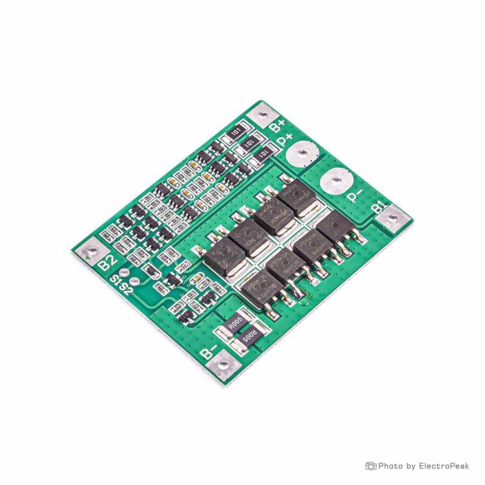
3S Lithium Battery Charging Protection Board - 11.1V, 25A
$0.8500
In stock
SKU
BAT-03-044
Volume discounts:
- +100 6 % $0.8000
- +300 8 % $0.7800
- +500 11 % $0.7600
- +1000 12 % $0.7500
Ships in 2-3 business days, then:
Free delivery in10-15 days by YunExpress on orders over $35.
Free delivery in5-7 days by DHL on orders over $200.
More shipping info
Shop with confidence Learn More
 2S Round Lithium Battery Charging Protection Board - 7.4V, 5A Previous
The BMS (Battery Management System) for 3S Li-ion/Li-Po battery packs with an 11.1V nominal voltage and a 25A maximum continuous discharge current is an essential component for ensuring the safe and efficient operation of lithium battery packs. Designed to manage and protect battery cells, the BMS offers features such as overcharge protection, over-discharge protection, and balanced charging. It is commonly used in applications such as electric vehicles, portable power banks, and solar energy storage systems, where multiple cells are connected in series to achieve higher voltages and capacities while maintaining individual cell health.
Specificatoins of 3S Lithium Battery Charging Protection Board - 11.1V, 25A:
- Nominal Voltage: 11.1V
- Maximum Continuous Discharge Current: 25A
- Battery Type: Designed for 3S (3 series) Li-ion or Li-Po battery packs
- Protection Features: Overcharge protection, over-discharge protection, short-circuit protection, balanced charging
- Balancing Current: Typically up to 60mA per cell
- Temperature Range: Operating temperature -20°C to +60°C
Features of 3S Lithium Battery Charging Protection Board - 11.1V, 25A:
- Safety and Protection: The BMS safeguards the battery pack by preventing overcharging, over-discharging, and short-circuiting, enhancing the lifespan and safety of the cells.
- High Discharge Current: With a maximum continuous discharge current of 25A, the BMS supports high-power applications while maintaining cell health.
- Cell Balancing: The BMS ensures that individual cells within the battery pack are balanced during charging, promoting uniform cell performance and extending battery life.
- Usage Tip:
- Install the BMS according to the manufacturer's guidelines and ensure proper wiring and connections. Monitor the battery pack's voltage regularly and take necessary precautions to prevent over-discharge or overcharge.
- Caution:
- Handle the BMS and battery pack carefully to prevent damage to the components. Ensure that the BMS is properly configured and compatible with the specific battery chemistry (Li-ion or Li-Po) and capacity. Exercise caution when working with high-power battery packs and adhere to recommended safety practices to avoid risks associated with lithium batteries.
Extra Notes:
Note:
This module does not perform charging operations and requires the use of another module to do that. This module is designed to protect the battery from abnormal conditions.
Steps to Follow
1. Connect the power source to the voltage buck module.
For a 3-cell battery pack, you should have a power supply of 16.2V (3x4.2). To do this, you will need a voltage buck module with a controlled current. This module needs a minimum of 14V on the input side in order to produce 12.6V at the output, so you should connect it to the voltage buck module.
2. Use a multimeter to adjust the output voltage.
3. To adjust the current, set the multimeter to the current mode (plug the multimeter cables into the correct ports) and then connect them to the output pads of the module and adjust the output current. Note that the output current should be less than the rated capacity of the batteries.
Connect the negative terminal of the first battery to the B- pad (V0) and the positive terminal to the B1 pad (V4.2). Then connect the negative terminal of the second battery to the B1 pad (V4.2) and the positive terminal to the B2 pad (V8.4). Similarly, connect the negative terminal of the third (last) battery to the B2 pad (V8.4) and the positive terminal to the B+ pad (V12.6).
Note: Follow this order to avoid damaging the BMS.
Then you can use P+ and P- as input and output, and connect these pads to the voltage buck module to perform the charging operation.
Next, connect the output of the Buck module to the p+ and p- pads to start charging. Remember that you should use these p+ and p- pads to use the battery.
Write Your Own Review


Please complete your information below to login.
Sign In
Create New Account