
Product added to cart

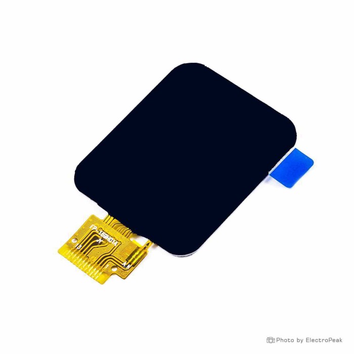
1.69inch TFT LCD - SPI, 12 Pin, ST7789V Driver
$2.2500
In stock
SKU
LCD-01-157
Volume discounts:
- +50 4 % $2.1600
- +100 6 % $2.1100
- +300 8 % $2.0600
- +500 10 % $2.0200
- +1000 12 % $1.9700
Ships in 2-3 business days, then:
Free delivery in 12-15 days by Tracked Economic Shipping on orders over $100.
Free delivery in 7-10 days by Express Shipping on orders over $300.
More shipping info

Shop with confidence Learn More
 1.69inch TFT LCD - Parallel, 18 Pin, ST7789V Driver Previous
1.69 inch TFT LCD ST7789V SPI Display Overview
This 1.69-inch full-color TFT display panel provides 240 x 280 resolution through an integrated ST7789V controller and a 4-wire SPI interface. It is built for compact embedded systems, mobile point-of-sale (MPOS) hardware, and portable instrumentation, connecting through an integrated 12-pin flexible printed circuit (FPC) tail rather than pre-soldered pin headers. The compact footprint suits custom PCB integrations, but it is not a drop-in choice for projects that require standard breadboard headers or pre-defined mounting tabs. For other panel formats and display technologies, browse the wider LCD display category.
Specifications of 1.69inch TFT LCD - SPI, 12 Pin, ST7789V Driver
- Display Size: 1.69 inches (diagonal)
- Resolution: 240 x 280 pixels
- Response Time: Min. 35 ms
- Contrast Ratio: 1000:1
- Brightness: 350 cd/m²
- Display Area: 27.97(H) x 32.63(V) mm
- Overall Size: 33.13 x 41.13 x 3.61 mm
- Pixel Arrangement: Vertical RGB
- Display Mode: Normally Black
- Viewing Angle: 80° in all directions
- Number of Colors: 262K
- Backlight Type: Edge LED
- Driver Chip: ST7789V
- Interface Type: 4-wire SPI
- Operating Temperature: -20°C to +70°C
- Storage Temperature: -30°C to +80°C
1.69 inch TFT LCD FPC Compatibility and 3.3V Requirements
Integrating this panel requires planning for its flat-flex connection and operating voltages. Unlike a breakout board, it terminates in a bare 12-pin FPC tail. The specification does not define the connector pitch or contact pinout, so inspect and meter the physical unit before laying out a custom PCB or buying a surface-mount FPC receptacle.
The ST7789V controller operates strictly within 3.3V-class logic and power levels (typically 2.5V to 3.3V VDD). Direct 5V signals on the data lines or power inputs will damage the display driver. When prototyping with a 5V board such as an Arduino Uno SPI controller, place bidirectional or unidirectional logic-level shifters between the microcontroller pins and the display lines. Native 3.3V platforms, including ESP32, RP2040, and STM32 boards, connect directly through SPI without level shifting.
| Integration Area | Specification / Requirement | Design Consideration |
|---|---|---|
| Physical Connection | 12-pin FPC ribbon | Requires a matching FPC connector or breakout adapter; pitch must be verified on receipt. |
| Host Interface | 4-wire SPI (SCLK, MOSI, CS, DC) | Uses fewer GPIO pins than parallel screens; requires hardware SPI support for smooth frame updates. |
| Logic & Supply Voltage | 3.3V nominal (2.5V–3.3V VDD) | Direct 5V logic will damage the controller; level conversion is mandatory for 5V development boards. |
| Driver Compatibility | ST7789V | Supported by open-source libraries including TFT_eSPI, LovyanGFX, and Adafruit_ST7789. |
| Touch Interface | None (non-touch) | Designed purely as a visual output display; external buttons or rotary encoders are required for navigation. |
For breadboard prototyping or projects that cannot accommodate surface-mount FPC soldering, use the header-equipped 1.69-inch SPI module. It places the 1.69-inch screen on a carrier PCB with a standard 8-pin 2.54 mm header.
1.69 inch TFT LCD ST7789V SPI Display Specifications Explained
Knowing how the panel specifications affect enclosure fit and graphical performance helps prevent costly design iterations.
| Specification | Listed Value | Why It Matters |
|---|---|---|
| Resolution | 240 x 280 pixels | The taller aspect ratio provides 40 extra vertical lines compared to square 240 x 240 panels, accommodating status headers and multi-row menus. |
| Active Area vs Overall Size | 27.97 x 32.63 mm display area; 33.13 x 41.13 x 3.61 mm body | Bezel borders and backlight housing extend beyond the screen area. Enclosure cutouts must match the active area, while internal cavities must clear the outer dimensions. |
| Display Mode | Normally Black | Unlit pixels block light effectively, yielding deep black backgrounds and high perceived color punch. |
| Contrast & Color Depth | 1000:1 contrast; 262K colors | Produces crisp typography, clear UI icons, and distinct tonal boundaries for graphical dashboards. |
| Brightness | 350 cd/m² | Suitable for indoor instruments, handheld terminals, and laboratory gear. Not suited for direct unshaded outdoor sunlight. |
| Interface | 4-wire SPI | Minimizes board trace routing and controller pin consumption, though frame rates are lower than parallel buses. |
Where high frame rates or animated interfaces exceed SPI bus bandwidth, the 1.69-inch parallel TFT display provides an 8-bit 8080 parallel interface for faster full-screen writes, but requires more microcontroller GPIO lines.
1.69 inch TFT LCD ST7789V SPI Display Limitations and Batch Checks
Bare display panels require attention to manufacturing tolerances. This unit is listed at 33.13 x 41.13 x 3.61 mm, with a 350 cd/m² brightness rating and an ST7789V driver. Across the broader electronics market, however, mechanically similar 1.69-inch 240 x 280 panels often show batch-level variations in outside glass dimensions, FPC pin pitches (varying between 0.3 mm, 0.5 mm, and 0.7 mm), and driver revisions such as ST7789V2 or ST7789V3.
Do not mill injection molds, cut final enclosure windows, or order fabrication PCBs until you have a physical production sample in hand. Measure the outer dimensions with calipers, identify pin 1 orientation on the FPC tail, and confirm the mating connector pitch. This panel does not feature touch input, so projects requiring interactive taps need an external touch overlay or mechanical input controls.
1.69 inch TFT LCD SPI vs 1.54 inch, 2 inch and Parallel Displays
Display selection comes down to physical footprint, interface routing, and panel geometry. The table below outlines direct differences across compatible display options.
| Model | Dimensions & Shape | Resolution | Driver IC | Interface & Connection | Intended Use |
|---|---|---|---|---|---|
| 1.69" SPI Panel (This Model) | 1.69" rectangular (33.1 x 41.1 mm) | 240 x 280 | ST7789V | 4-wire SPI; 12-pin FPC | Custom compact PCBs and low-profile enclosures. |
| 1.69" TFT LCD SPI Module | 1.69" rectangular on breakout PCB | 240 x 280 | ST7789V2 | SPI; 8-pin 2.54 mm header | Rapid breadboard prototyping without FPC soldering. |
| square 1.54-inch ST7789V display | 1.54" square panel | 240 x 240 | ST7789V | SPI; 12-pin 0.7 mm FPC | Square interfaces and symmetrical meter gauges. |
| circular 1.28-inch display | 1.28" circular panel | 240 x 240 | GC9A01 | SPI; 12-pin 0.7 mm FPC | Round instrumentation dials and watch-face interfaces. |
| 2-inch SPI TFT display | 2.0" rectangular panel | 240 x 320 | ST7789V2 | SPI; 12-pin 0.7 mm FPC | Larger handheld equipment needing extra readable area. |
| 1.69-inch parallel TFT display | 1.69" rectangular panel | 240 x 280 | ST7789V | 8-bit 8080 parallel; 18-pin FPC | High-update UIs where sufficient GPIO pins exist. |
| two-color I2C OLED alternative | 0.96" rectangular module | 128 x 64 | SSD1306 | I2C; 4-pin header | Simple low-power numeric readouts and text status. |
1.69 inch TFT LCD ST7789V SPI Setup Check
Use this initial bring-up procedure to verify display function before integrating the panel permanently:
- Physical Inspection: Inspect the 12-pin FPC tail under magnification. Check trace integrity, measure contact pitch, and confirm pin 1 orientation.
- Breakout Connection: Insert the FPC tail into a matching test receptacle or carrier board. Connect it to your development board using prototyping jumper wires.
- Power & Logic Level Check: Supply 3.3V to the display VDD and ensure logic signals do not exceed 3.3V. Place level translators in line when driving it with a 5V controller.
- SPI Signal Wiring: Connect SCLK, MOSI, CS (Chip Select), DC (Data/Command), and RST (Reset) to your controller hardware SPI bus. Connect the backlight anode and cathode lines according to your carrier board circuitry.
- Firmware Configuration: Open your graphics library, such as TFT_eSPI or LovyanGFX. Select the ST7789 driver profile, map your GPIO pin assignments, and explicitly configure the screen resolution to 240 x 280 pixels.
- Test Pattern Flash: Upload a simple primary-color cycling sketch (Red, Green, Blue) to confirm screen initialization, color mapping, and display orientation.
If the screen remains completely dark or pure white, check the backlight power circuit and confirm that the CS, DC, and RST pin definitions in your firmware match the physical wiring. A shifted or cropped test image, or static bands, indicates that the library is likely defaulting to a 240 x 240 offset. Correct the resolution definition, then adjust row/column start offsets in your display configuration file.
1.69 inch TFT LCD ST7789V SPI FAQ
Is this a ready-to-wire SPI breakout board?
No. This product is a bare display panel terminating in a 12-pin FPC cable. It does not include 2.54 mm header pins, mounting holes, or integrated level shifting. Connection requires a matching FPC connector, adapter, or custom PCB.
Will this 1.69 inch TFT LCD work with an Arduino Uno?
Yes, but only through external 3.3V logic-level shifters. The Arduino Uno outputs 5V logic on its SPI lines, which will damage the 3.3V ST7789V controller if connected directly.
What FPC connector pitch does this display use?
The listing specifies a 12-pin FPC connection but does not state the pin pitch. Similar displays in this format use 0.3 mm, 0.5 mm, or 0.7 mm pitches, so measure the received unit before buying connectors or finalizing a PCB design.
What resolution should I select in my ST7789 library?
Set the display library configuration to 240 x 280 pixels. Selecting 240 x 240 causes image truncation or coordinate offsets along the vertical axis.
Is the brightness 350 cd/m² or 500 cd/m²?
The specification for this display is 350 cd/m². Some comparable OEM variants list higher typical figures, but treat 350 cd/m² as the operational baseline for your lighting design.
Does this display include touch input?
No, this is a non-touch display panel. Interactive projects require external buttons, encoders, or a separate touch digitizer overlay.
Should I choose the SPI panel or the 1.69-inch parallel display?
Choose this SPI version to conserve microcontroller GPIO pins and simplify routing on compact boards. Choose the 1.69-inch parallel TFT display when your microcontroller has ample pins and the interface requires higher refresh rates over an 8-bit parallel bus.
For bench testing, an MCU-side breadboard prototyping setup helps organize your controller and level shifters, provided the display is mounted on an appropriate FPC adapter.
Purchase Decision Guidance:
- Choose this panel for custom PCB designs requiring a compact, low-profile 1.69-inch 240 x 280 color interface with 4-wire SPI communication.
- Choose the 1.69" TFT LCD SPI Module when you need the same 240 x 280 format with standard 2.54 mm pin headers for immediate breadboard use.
- Choose the 1.69" Parallel TFT LCD when your application demands higher frame rates and your controller can allocate 8 parallel data pins plus control lines.
- Choose the two-color I2C OLED alternative when you only require simple text, low current consumption, and two-wire communication without full color.
Buying Checklist
- Confirm that a 1.69-inch vertical 240 x 280 layout fits your user interface layout.
- Confirm that 4-wire SPI is your intended communication bus.
- Confirm that your project hardware can integrate a 12-pin FPC ribbon connection.
- Plan to verify the physical FPC pitch and pinout on a sample unit before fabricating production PCBs.
- Ensure your circuit supplies 3.3V-class power and logic levels.
- Procure a logic-level shifter if you intend to interface with a 5V controller such as an Arduino Uno.
- Confirm that your project does not require touch screen input.
- Use the 33.13 x 41.13 x 3.61 mm outer dimensions and 27.97 x 32.63 mm active area for preliminary CAD modeling, verifying on physical hardware before final tool runs.
- Verify that 350 cd/m² brightness matches your operating ambient lighting conditions.
- Select the header-equipped 1.69" TFT LCD SPI Module if direct breadboard wiring is required.
| Platform | Arduino, ESP, Raspberry Pi Pico, STM |
|---|---|
| Display Size | 1.69 inch |
| Display Size Range | 1 inch to 1.99 inch |
| Display Resolution | 240 x 280 pixels |
| Display Driver | ST7789V |
| Display Interface | SPI |
| Panle Type | TFT |
| Display Color Type | Full Color |
| Backlight Type | White LED |
| Viewing Angle (°) | 80 degrees (All directions) |
| Operating Temp (°C) | -20 to 70 |
| Operating Voltage (V) | 1.8V, 3.0V |
| Pins | 12 |
| Dimensions (mm) | 27.97 x 32.63 mm; 33.13 x 41.13 x 3.61 mm |
| Pixel Pitch | 0.11655 x 0.11655 mm |
| Brightness | 350 nits |
Write Your Own Review

Please complete your information below to login.
Sign In
Create New Account