
Product added to cart

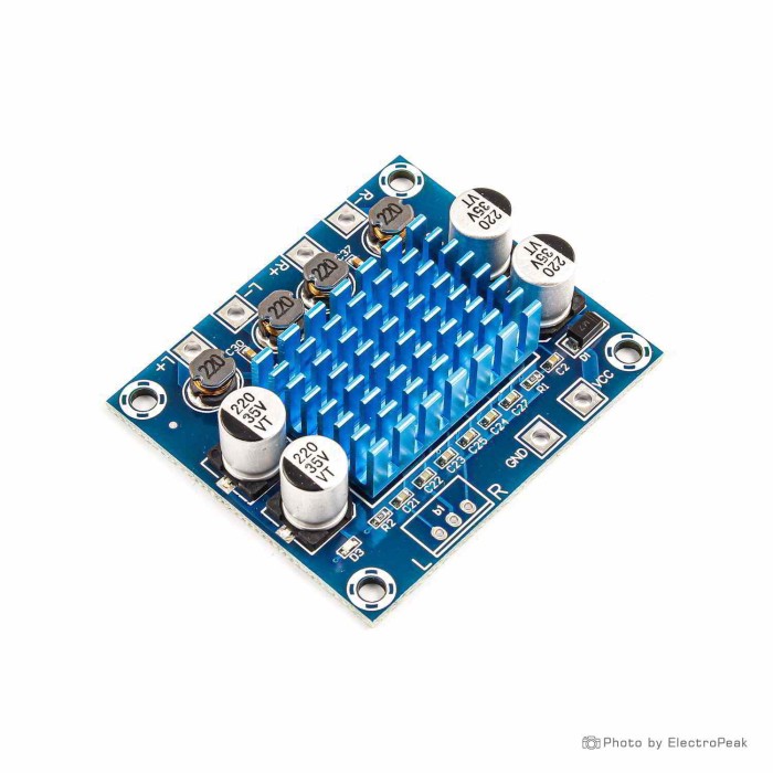
XH-A232 Digital Power Amplifier Board - 2x30W, Class D
$0.9000
In stock
SKU
SEN-17-125
Volume discounts:
- +50 3 % $0.8700
- +100 6 % $0.8500
- +300 8 % $0.8300
- +500 10 % $0.8100
- +1000 11 % $0.8000
Ships in 2-3 business days, then:
Free delivery in 12-15 days by Tracked Economic Shipping on orders over $100.
Free delivery in 7-10 days by Express Shipping on orders over $300.
More shipping info

Shop with confidence Learn More
 XY-AP15H Bluetooth Stereo Power Amplifier Board - 10W/15W/20W Previous
XH-A232 Amplifier Board Review
The XH-A232 is a compact Class D stereo audio amplifier board based on the Texas Instruments TPA3110 amplifier chip. It operates across a DC 8V to 26V range and is intended for DIY wired stereo speakers, electronics projects, bench audio testing, and repair installations. Comparable marketplace listings place boards of this type in the $1–7 range, making it a low-cost analog amplification stage for builders comfortable soldering their own connections and supplying an external audio source with volume control.
The board offers a straightforward analog amplifier in a small 53×45×14 mm footprint, but it is not a plug-and-play all-in-one audio solution. It lacks onboard Bluetooth, has no built-in volume knob, and does not deliver a genuine 2×30W of clean stereo output. Buyers seeking wireless playback, no-solder screw terminals, or dedicated subwoofer power need supplemental hardware or a different amplifier board entirely.
Specifications of XH-A232 Digital Power Amplifier Board - 2x30W, TPA3110
- Amplifier chip: TPA3110 audio amplifier chip
- Power supply voltage: DC8V-26V
- Output power: Varies based on voltage and speaker impedance
- Output power: Up to 15W per channel at 24V and 4Ω
- Max output power: 30W+30W
- Input interface: Soldering pads for audio input
- Speaker output: Soldering pads for connecting speakers
- Output impedance: 4-8ohm
- Current: More than 3A
- Signal to noise ratio: 100db
- Weight: 21g
- Dimensions: 53*45*14mm
The XH-A232's appeal is its minimal footprint, simple solder-pad layout, and solid sound reproduction relative to its low component cost. With appropriate power and speakers, it handles everyday amplification tasks cleanly. Builders who need an integrated wireless receiver, factory-fitted terminal blocks, or quiet-room HiFi operation with zero background hiss should consider other related audio modules and sound-player boards before committing to this hardware.
XH-A232 Output Power, Voltage and Speaker Load
The listed specifications state both "Up to 15W per channel at 24V and 4Ω" and "Max output power: 30W+30W." These figures need context. In practical two-channel stereo operation, the TPA3110 board reliably delivers approximately 10W to 15W per channel of clean, low-distortion audio. The 30W rating reflects a mono parallel bridge-tied load (PBTL) condition or an extreme bridge-tied load (BTL) drive state pushed to 10% total harmonic distortion (THD), which produces severe audible clipping. For standard listening, plan on 10–15W per channel.
The board operates across a DC 8V to 26V input range. A 12V supply provides modest sound levels suited to small desk monitors or background audio. At 18V to 24V, the amplifier reaches its full practical volume. The specification of "Current: More than 3A" is power-supply sizing guidance rather than continuous current draw. Under normal full-power stereo playback at 24V, the board draws approximately 1.4A to 1.5A. A 3A or higher supply provides the dynamic headroom needed to prevent voltage sags and crackling during heavy bass transients.
Speaker load matching is critical for thermal stability and chip protection:
| Parameter | Specification / Guideline | Real-World Application Note |
|---|---|---|
| Listed Impedance | 4–8Ω | Compatible with passive stereo speaker drivers. |
| Supply > 15V Continuous | 4.8Ω minimum | Texas Instruments TPA3110D2 safety limits require at least 4.8Ω for continuous operation above 15V. Use 8Ω speakers when running at 18–24V. |
| Supply ≤ 15V Operation | 4–8Ω acceptable | 4Ω speakers run safely at 12V to 14.4V without excessive thermal stress. |
| Unacceptable Loads | < 4Ω (e.g., 2Ω loads) | Never wire 2Ω drivers or parallel multiple speakers onto a single channel; this triggers overcurrent shutdown and can damage the IC. |
For clean stereo power beyond 15W per channel or large floorstanding cabinets, move to a higher-power TPA3116D2 stereo amplifier board rather than overdriving this module.
XH-A232 Input, Volume Control and Bluetooth Requirements
The term "digital power amplifier" refers only to Class D pulse-width-modulation switching topology, not to a digital audio data interface. The XH-A232 accepts standard analog stereo signals through three dedicated solder pads: Left channel (L), Right channel (R), and Audio Ground (GND). It does not accept I2S, optical, S/PDIF, or USB audio data directly.
The board has no onboard Bluetooth receiver or onboard potentiometer. Control loudness from the audio source—such as a smartphone, PC, external DAC, or microcontroller audio shield—or through a dual-gang 10kΩ or 50kΩ logarithmic potentiometer wired before the input pads. Powering the board with a high-output source connected and no upstream attenuation causes it to play at maximum gain immediately.
Choose the input configuration that fits your build:
- For integrated volume attenuation, a standard 3.5 mm auxiliary jack, and a DC barrel socket, consider an amplifier board with volume control and input jack.
- Compact, single-speaker wireless audio is better served by a mono Bluetooth amplifier module, which provides direct pairing on a single channel.
- Projects needing multi-source audio handling with Bluetooth, auxiliary input, USB flash drive playback, and mobile app control can use an adjacent option such as a multi-input Bluetooth audio board to simplify assembly.
- Direct wireless stereo streaming without a separate receiver is the role of an integrated Bluetooth stereo amplifier board, which removes the extra module from your signal path.
XH-A232 Amplifier Board Limitations and Common Problems
A bare-board amplifier module comes with several hardware quirks and design trade-offs:
- Real Output Ceilings: Clean stereo output tops out at 10–15W per channel. Expecting sustained 30W+30W output in normal stereo conditions leads to heavy clipping and thermal cutoff.
- Audible Idle Hiss: Many generic production batches are factory-strapped for maximum 36 dB gain. The high baseline gain amplifies source noise and input floor hiss, producing audible hiss through sensitive speakers even when no audio is playing.
- Turn-On Pop: The TPA3110 architecture exhibits a brief DC offset settling transient at power-up, heard as a "thump" or "pop" through the speakers. An external delayed speaker protection relay board eliminates this transient.
- Low-End Roll-Off: Frequency response testing on common batches shows noticeable bass roll-off below 200 Hz. The board is tuned for vocal clarity and general-purpose stereo listening, making it poorly suited for dedicated subwoofer builds.
- Heatsink Retention: The board includes a small factory heatsink attached over the IC. Detached heatsinks have been observed after shipping transit, and prolonged operation near 24V into 4Ω causes significant heating. Installing a supplemental heatsink for sustained output and ensuring cabinet ventilation prevents thermal throttling.
- Silkscreen Inaccuracies: Some production runs have misprinted polarity labels on the right-channel speaker pads. If stereo audio sounds hollow, diffuse, or lacks center presence, reverse the positive and negative leads on one speaker to correct phase alignment.
- Supply Sensitivity: Testing the board with an underpowered 12V 1A adapter frequently causes crackling, audio dropouts, and cycling brown-out resets when volume peaks hit.
Avoid this board if you need dead-silent background operation for nearfield desktop listening, plug-and-play wiring without a soldering iron, built-in wireless connectivity, or deep sub-bass reproduction.
XH-A232 vs XH-M543 and PAM8610 Amplifier Boards
A comparison with common alternative stereo boards shows the trade-offs in power delivery, operating voltage, and onboard features:
| Module | Amplifier IC | Stated Output Power | Supply Voltage | Dimensions | Input & Output Interface |
|---|---|---|---|---|---|
| XH-A232 | TPA3110 | Up to 15W/ch (24V 4Ω); 30W+30W max | DC 8–26V | 53*45*14 mm | Solder pads; analog line-in; no volume knob |
| DY-AP3015 | TPA3110 | Up to 15W/ch; 30W*2 max | DC 8–26V | 53*45*14 mm | Identical hardware listing; solder pads |
| XH-M543 | TPA3116D2 | Up to 2x120W (at 24V) | DC 12–26V | 92*68*16 mm | Screw terminals, pins, dual onboard trim pots |
| XH-M181 | PAM8610 | 2x15W (4Ω) / 2x10W (8Ω) | DC 6–15V | 28*22*2.5 mm | Solder pads; compact low-voltage layout |
| PAM8610 with Pot | PAM8610 | 2x10W (8Ω) / 2x20W (4Ω) | DC 7–15V | Compact module | Volume knob, 3.5 mm AUX jack, DC barrel jack |
The identical 2x30W stereo amplifier module listing is an exact-tier alternative source for the same baseline board. Among different designs, start with your supply voltage and connection preferences. For a small battery-powered project running from a 7.4V or 12V pack, a compact low-voltage stereo amplifier option based on the PAM8610 provides a significantly smaller footprint. Need physical volume control and quick-connect cables without custom wiring? Choose an amplifier board with volume control and input jack. For higher-voltage workshop or living room systems where 15W per channel is insufficient, a higher-power TPA3116D2 stereo amplifier board provides substantially higher clean headroom.
XH-A232 Wiring and First Power-On Check
As an analog hardware amplifier module, the XH-A232 requires no firmware, software drivers, or digital configuration. Test it on a workbench before final enclosure mounting to verify channel operation and component integrity.
- Inspect the Board: Check the pre-mounted heatsink to ensure it sits flush on the TPA3110 IC and does not bridge adjacent surface-mount components.
- Prepare Connections: Strip and tin hookup wire leads. Solder audio input wires to L, R, and GND. Connect an analog audio source (phone, DAC, or PC) with the source volume set to minimum.
- Connect Speakers: Solder leads from two passive 4–8Ω speakers to the L+, L-, R+, and R- output pads. Do not link the negative terminals together; each channel runs as an independent bridge-tied load.
- Connect Power: Solder power leads to the VCC and GND pads, double-checking polarity. A reversed DC input will destroy the chip.
- Initial Power-On: Apply DC power. For bench evaluation, a 12V test power supply provides a safe, modest-output testing baseline before deploying a larger 24V unit. A brief click or pop from the speakers is normal during startup.
- Audio Verification: Play a stereo test track and gradually increase source volume. Confirm that both channels produce balanced, clear audio. If the sound stage feels hollow or bass is cancelled out, reverse the positive and negative leads on one speaker pad.
For modular wiring, some builders adapt the board pads with a soldered terminal-block conversion. Check pad spacing on your specific board before soldering, as terminal pin pitch may not match all generic PCB hole spacings.
Required, Recommended, and Optional Accessories
Required
- DC Power Supply: 8–26V DC supply. An 18–24V supply rated at 3A or higher is required for full-volume output.
- Passive Stereo Speakers: Two 4–8Ω passive speaker drivers. Use at least 4.8Ω drivers when operating continuously above 15V.
- Soldering Equipment and Wire: Soldering iron, solder, and 20–24 AWG hookup wire for power, input, and speaker pad connections.
- Analog Audio Source with Attenuation: Smartphone, PC, preamplifier, or external DAC capable of controlling output volume.
Recommended
- Bench Test Power Supply: A 12V 2A switching power supply for safe initial bench testing and low-power installations.
- Supplemental Cooling: An supplemental heatsink for sustained output to keep the IC cool during continuous high-volume operation.
- External Potentiometer: A 10kΩ or 50kΩ dual-gang potentiometer wired to the input pads if your audio source lacks volume adjustment.
- Bluetooth Receiver Board: An upstream wireless audio decoder if Bluetooth streaming is needed.
- Project Enclosure: A vented non-conductive enclosure to protect bare solder points and provide airflow.
Optional
- Delayed Speaker Protection Relay: Suppresses power-on pop transients in permanent speaker cabinets.
- Bulk Input Electrolytic Capacitor: Placed across VCC and GND near the board to reinforce weak power supply lines during heavy audio peaks.
- Ground-Loop Audio Isolator: Resolves hum and whine when the audio source and amplifier share an unisolated common DC power bus.
- Screw Terminal Blocks: A soldered terminal-block conversion for modular wire connection, subject to pad pitch verification.
XH-A232 Amplifier Board FAQ
Is the XH-A232 really 30W+30W?
No, not under clean stereo listening conditions. The board delivers approximately 10W to 15W per channel of clean audio across typical supply voltages. The 30W figure refers to a mono PBTL configuration or heavy 10% THD distortion clipping.
Does the XH-A232 have Bluetooth?
No, the board has no wireless hardware. It accepts only analog stereo signals soldered to its input pads. For portable, low-power battery-operated Bluetooth playback, consider a low-power portable Bluetooth speaker module or browse the broader selection of related audio modules and sound-player boards.
Does the XH-A232 have a volume knob?
No, there is no onboard potentiometer or volume switch. Volume must be attenuated from your input device (phone, PC, or DAC) or by an added external potentiometer placed before the input pads.
Can the XH-A232 run from 12V?
Yes, 12V falls within the DC 8V to 26V range. Output volume will be modest compared with 18V or 24V operation. Expect around 5W to 10W per channel at 12V depending on speaker impedance.
What speakers can I use with the XH-A232?
Use two passive 4Ω to 8Ω speaker drivers. For continuous operation above 15V, select speakers rated at 4.8Ω or higher; standard 8Ω drivers work well and help prevent thermal overload. Do not use 2Ω drivers.
Can I bridge the XH-A232 outputs for mono?
No. Each stereo channel is already configured internally as a bridge-tied load (BTL). Tying the left and right speaker outputs together triggers short-circuit protection and can damage the output stages.
Why does my XH-A232 hiss at low volume?
Many generic boards are factory-set to high gain (36 dB). This amplifies input line noise and the IC's internal noise floor, creating audible hiss on sensitive speakers during silent passages.
Why does the XH-A232 pop when I turn it on?
The TPA3110 IC produces a small DC offset settling transient when first energized. While harmless to most robust drivers, an external speaker protection relay circuit can mute the output until rails stabilize.
Is the XH-A232 suitable for a subwoofer?
No. The board exhibits documented frequency roll-off below 200 Hz on common production batches and lacks low-pass filtering. Dedicated 2.1 or mono subwoofer amplifier boards are better suited to bass reproduction.
What is included with the XH-A232?
You receive the assembled amplifier PCB with a pre-attached heatsink. Power supplies, speakers, audio input cables, volume controls, and mounting hardware are not included and must be sourced separately.
XH-A232 Purchase Decision Summary
Ideal for:
- Builders constructing compact, low-cost wired stereo speakers using salvaged 4–8Ω drivers.
- Adding an analog audio amplification stage to Raspberry Pi, ESP32 DAC, or arcade cabinet projects.
- Workshop, garage, or utility audio systems where simple solder-pad construction and budget pricing are top priorities.
- Hobbyists who already own a 12–24V power supply and an analog source with software volume control.
Maybe for:
- 12V vehicle or battery-powered setups, provided you accept modest output volume levels.
- Builders willing to wire their own external Bluetooth receiver, volume potentiometer, or speaker relay.
Avoid if:
- You expect true 2×30W RMS clean stereo output.
- You need built-in Bluetooth, a physical volume knob, or no-solder screw terminals.
- You are building a quiet-room nearfield HiFi setup where idle background hiss is unacceptable.
- You want to power a dedicated subwoofer driver.
XH-A232 Buying Checklist
- [ ] I need an analog stereo amplifier board and have tools to solder wire leads directly to PCB pads.
- [ ] I understand this board does not include onboard Bluetooth or a physical volume knob.
- [ ] I have an audio source (phone, PC, or external preamp) capable of controlling output volume.
- [ ] I have a DC power supply between 8V and 26V (preferably 18–24V, 3A+ for full performance).
- [ ] I have two passive 4–8Ω speakers (minimum 4.8Ω if operating continuously above 15V).
- [ ] I am planning around 10–15W per channel of clean audio rather than 30W+30W continuous RMS.
- [ ] I will check heatsink attachment and test speaker polarity on the bench before sealing my enclosure.
| Interface Type | Analog |
|---|---|
| Operating Voltage (V) | 12-24 |
| Operating Current (mA) | >3000 |
| Operating Temp (°C) | -40 to 85 |
| Dimensions (mm) | 53x45x14 |
| Mounting Type | Screw holes |
| Audio Function | Amplifier |
| Output Power | 30W |
| Speaker Impedance (Ω) | 4Ω, 8Ω |
| Sampling Rate (Hz) | 14kHz-100kHz |
| Weight (g) | 21 |
| Input Types | Soldering pads |
| Bluetooth Ver. | No |
| Output Type | Analog |
| Channels | 2-channel |
| Chipset | TPA3110 |
| Signal-to-Noise Ratio (SNR) | 100 dB |
Write Your Own Review

Please complete your information below to login.
Sign In
Create New Account