
Product added to cart

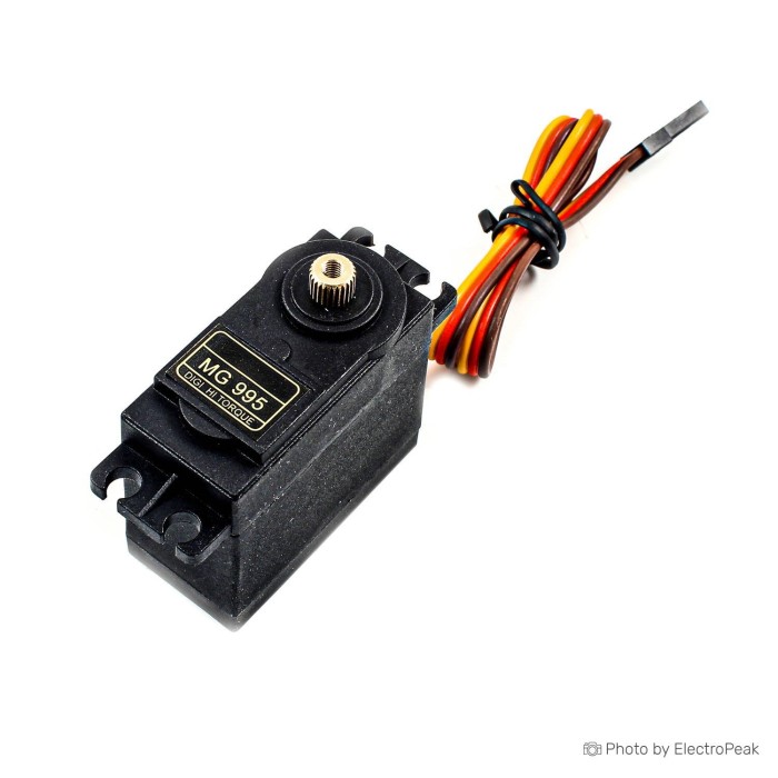
TowerPro MG995 55G Metal Gear Servo
$2.6900
In stock
SKU
MTR-06-005
Volume discounts:
- +25 3 % $2.6000
- +100 5 % $2.5600
- +300 7 % $2.5100
- +500 8 % $2.4700
- +1000 10 % $2.4200
Ships in 2-3 business days, then:
Free delivery in 12-15 days by Tracked Economic Shipping on orders over $100.
Free delivery in 7-10 days by Express Shipping on orders over $300.
More shipping info

Shop with confidence Learn More
 TowerPro Mini Servo SG-90 9G Servo Previous
MG995 Servo Review: 55G Metal-Gear Positional Servo
The TowerPro MG995 is a standard-size 55g positional PWM servo for robotics, steering linkages, and general electronics hardware that needs controlled movement and steady holding power. With all-metal gears and a nominal 180° rotation range, it delivers substantial torque for non-critical hobby and prototype mechanisms when used with an external power source. MG995-family hardware has documented batch variation in travel limits, centering stability, and electrical demand, so it suits assemblies where operating ranges can be verified before final mounting—not precision-calibrated or safety-critical machinery. Compare form factors and control types across project scales in the broader servo motor category.
Specifications of TowerPro MG995 55G Metal Gear Servo
- Model: TowerPro MG995 Metal Servo
- Torque: 13kg/cm
- Deadband: 4μs
- Wirelength: 30cm
- WorkingVoltage: 4.8-7.2V
- Operatingcurrent: 100mA
- Dimensions: 40.7mm x 19.7mm x 42.9mm
- UnloadSpeed: 4.8V0.17sec/60°
- UnloadSpeed: 6.0V0.13sec/60°
- Dimension: mm40.8x20x38
- Weight: 55g
- Rotation range: 90~90- degrees
- Speed: 6.0V: 0.16sec/60°
- Speed: 4.8V: 0.20sec/60°
- Torque: 6.0V: 10kgf.cm
- Torque: 4.8V: 8.5kgf.cm
- Voltage: 4.8V-9V
- PWM pulse frequency: 50Hz
- Operating temperature: 0-55 ºC
MG995 Servo Specifications Explained
These physical and electrical specifications matter when you are designing a mechanism that must stay within safe mechanical limits without stalling or overheating.
| Specification | Listed Value | Engineering Interpretation |
|---|---|---|
| Mass & Dimensions | 55g; 40.7 x 19.7 x 42.9 mm / 40.8 x 20 x 38 mm | The standard 55g casing provides substantial structural rigidity, but two varying dimension sets are listed for this model. Measure physical clearances and mounting bracket spacing from delivered stock before machining rigid chassis parts. |
| Holding & Dynamic Torque | 13kg/cm (headline); 8.5 kgf·cm (4.8V); 10 kgf·cm (6.0V) | Torque values represent maximum stall torque at the motor shaft rather than continuous working capacity. Available lifting force decreases proportionally as lever arm length increases; always design for dynamic loads well below stall limits. |
| Operating Voltage | 4.8–7.2V (working); 4.8V–9V (voltage listing) | The listed voltage fields conflict. While 4.8V to 6.6V (or up to 7.2V) aligns with standard 4-to-5 cell NiMH or 2S LiFe hobby setups, 9V operation lacks validation across technical documentation and risks damaging the internal motor driver. Confirm batch limits before exceeding 6.0V–7.2V. |
| No-Load Transit Speed | 0.20–0.17 sec/60° (4.8V); 0.16–0.13 sec/60° (6.0V) | Transit times scale with supply voltage. Higher supply voltage produces faster travel response, though sudden high-speed direction changes create higher back-EMF spikes. |
| Lead Length | 30cm | The integrated three-wire lead is sufficient for bench tests and compact chassis, but larger mechanical layouts will require a short servo extension cable to reach power distribution rails cleanly. |
| Control Deadband | 4μs | Defines the pulse width change required before internal circuitry initiates motor movement. A 4μs window reduces constant hunting at the expense of minute micro-positioning accuracy. |
Where a 55g case creates balance or space penalties in compact mechanisms or lightweight camera gimbals, the TowerPro MG90S offers a 13.4g footprint as a smaller servo for compact mechanisms.
MG995 Servo Power and PWM Compatibility
The MG995 responds to standard 50Hz pulse-width modulation (PWM), making it electronically compatible with Arduino, ESP32, Raspberry Pi, and standard RC receivers. Control requires pulse widths typically spanning from 1000μs to 2000μs, or 500μs to 2500μs depending on rotation calibration, which map directly to target shaft angles.
A separate regulated external power supply is essential. Although the specification sheet lists an operating current of 100mA, that figure accounts only for unconstrained, idle movement. Under actual operation, MG995-family servos exhibit startup and stall current spikes of 1.0A to 1.5A or higher per motor. Powering this unit directly from the 5V output rail of an Arduino or ESP32 will collapse the logic rail, causing immediate microcontroller brownouts, erratic twitching, and repeated board resets.
Run power (V+) and ground (GND) directly from an external regulated 5V to 6V power source to the servo. Route only the PWM logic pin from your microcontroller to the servo's signal input. Connect the microcontroller's GND pin to the external power supply's negative rail to establish a shared ground reference. For complex robots with multiple servos, a dedicated multi-servo PWM controller driven over I2C reduces timing overhead and wiring congestion.
MG995 Servo Limitations: Torque, Travel and Centering
Successful MG995 integration starts with understanding its mechanical trade-offs. The prominent 13kg/cm torque rating is a stall-condition figure; sustained operation near this threshold causes rapid motor heating, accelerated gear train stress, and potential driver failure. In real-world mechanisms, calculate usable dynamic payload capacity at roughly one-third to one-half of the stall rating, factoring in your specific lever arm distance.
Rotation travel needs empirical validation. Although listed with a 180° rotation range, and alternatively as 90~90- degrees, MG995-family units often show mechanical stop limits near 120° to 160° depending on production batch and internal potentiometer geometry. Forcing the motor to seek an angle beyond its physical stops draws peak stall current continuously. This can strip gears or burn out drive transistors within seconds. Determine software endpoint limits with an unloaded shaft before securing rigid linkages.
Centering repeatability and gear train backlash are common user frustrations. Position hunting, slight overshoot, and mechanical buzzing around neutral positions frequently appear under static loads. Generic MG995 clones are widespread, so internal construction—including intermediate gear materials, bearing types, and motor control electronics—can vary across production batches. Before final installation in a permanent assembly, a manual servo endpoint and centering test helps isolate deadband jitter from software faults. Applications requiring high precision, zero-backlash, and position telemetry call for a smart servo for feedback-driven robotics with internal sensor feedback and programmable serial bus control that standard PWM hobby servos cannot provide.
MG995 Servo Uses and Accessories
The MG995 has extensive practical use in maker projects where high holding force matters more than absolute positional accuracy. Documented installations include:
- Robotic Arms and Grippers: Base rotation, shoulder joints, and claw actuators handling non-precision manipulation.
- RC Vehicle Steering: Steering racks on 1/10-scale rock crawlers and trucks requiring high torque over rough terrain.
- Solar Tracking Mounts: Dual-axis elevation and azimuth pivots moving balanced panel assemblies on low-duty-cycle schedules.
- Automated Latches and Feeder Gates: Physical mechanisms requiring discrete open/close mechanical travel against moderate mechanical resistance.
Where loads are modest and plastic gears provide sufficient durability, the TowerPro SG-5010 is a lower-load standard servo option that reduces mechanical weight without requiring heavy metal gearing.
A functional MG995 build requires a few essential hardware components:
- Required: Use a regulated external 5V–6V DC power supply capable of delivering at least 1.5A to 2A peak current per servo, along with a compatible PWM signal source such as an Arduino, ESP32, or dedicated RC receiver. Mechanical horns and linkages matching the delivered output spline are also required to connect to external hardware.
- Recommended: Use high-gauge wiring and power distribution buses to handle transient current, along with a long servo extension cable to route signals across larger frames or robot arms.
- Optional: Add decoupling electrolytic capacitors (470μF to 1000μF) across the servo power rail to smooth startup voltage dips, and use dedicated multi-channel driver boards for multi-axis setups.
MG995 Servo Quick Start with Arduino
Use this initial verification sequence to confirm motor motion, center alignment, and operating current before mounting the servo in a rigid mechanical frame.
- Visual Inspection: Check the casing, lead wires, and output spline for structural defects or loose wiring at the strain relief joint.
- Wire the Power Rail: Connect the servo's power lead (typically red) to the positive terminal of a regulated 5V–6V power supply, and the ground lead (typically brown or black) to the supply's negative terminal.
- Establish Common Ground: Connect an external jumper wire between the power supply negative terminal and the Arduino GND pin.
- Connect Signal Line: Connect the servo signal lead (typically yellow or orange) to Arduino digital pin 9.
- Initialize Position Without Horn: Upload a basic servo centering sketch using the standard Arduino
Servo.hlibrary commanding a 90° angle (approximately 1500μs pulse width) while the output shaft is completely detached from any horn or mechanism. - Mount Linkage: Once the motor seeks its center without buzzing or overheating, press the servo horn onto the spline at your desired mechanical zero point and fasten the retention screw.
- Calibrate Sweeps: Command limited angular sweeps, for example between 45° and 135°, before expanding to the full stroke. Stop immediately if the motor hums loudly or fails to reach commanded angles due to mechanical interference.
For detailed step-by-step code samples and advanced timer configurations, refer to the complete MG995 Arduino wiring guide.
MG995 Servo FAQ and Buying Checklist
Can I power this MG995 servo from an Arduino or ESP32 5V pin?
No. An Arduino or ESP32 logic pin cannot deliver the dynamic current this servo requires. The microcontrollers can provide the 50Hz PWM signal, but supplying motor current from the development board causes brownout resets under load. Always power the motor through an external regulated 5V–6V supply with grounds connected.
What voltage should I use with this MG995 servo?
Operate the servo between 4.8V and 6.0V, up to 7.2V if supported by your batch. Although one field lists 4.8V–9V, 9V operation is unsupported in technical family documentation and risks damaging the internal motor driver circuit. Verify manufacturer batch details before considering anything above 7.2V.
Does this MG995 servo really provide 13kg/cm torque?
The 13kg/cm figure is a theoretical maximum stall torque, not continuous working output. At 4.8V, holding performance is rated at 8.5 kgf·cm, rising to 10 kgf·cm at 6.0V. Calculate lever distances carefully and plan continuous operating loads substantially lower than stall ratings.
Does the MG995 servo rotate a full 180 degrees?
Not always across every production batch. While listed for 180° motion, internal mechanical stops and potentiometer variations often restrict usable safe travel to between 120° and 160°. Test your delivered unit unloaded to map software endpoints before connecting rigid linkages.
Why is my MG995 servo buzzing, jittering, or resetting the controller?
Persistent buzzing and controller resets usually result from low supply current, voltage drop across thin wiring, a missing shared ground connection, or commanding the servo past its internal physical stops. Ensure your supply delivers at least 1.5A peak current and that PWM pulse limits match physical shaft travel.
Is this MG995 servo suitable for a robot arm?
Yes, provided the arm design accounts for gear backlash, deadband settling, and realistic working loads. It excels in low-cost articulated demonstrators, but mechanisms demanding high absolute accuracy, repeatable sub-millimeter positioning, or closed-loop feedback should consider a serial bus servo with feedback instead.
Is this MG995 servo suitable for RC aircraft?
No. This servo is not recommended for safety-critical primary flight controls. Documented batch variations, centering drift, and deadband characteristics make it unsuitable for aircraft surfaces where uncommanded movement or failure leads to catastrophic loss.
Will a Futaba or JR horn fit this MG995 servo?
MG995 servos commonly share dimensions with standard 25T spline ecosystems, but tolerances vary across clone manufacturers. Check horn engagement by hand before applying mechanical force to avoid stripping the shaft spline.
Are horns, screws, and mounting hardware included?
In-box accessory contents are not formally specified for this product listing. Do not assume mounting hardware, grommets, or specific horn shapes are bundled; verify existing hardware or prepare to source 25T-compatible servo accessories separately.
Purchase Decision Summary
- Ideal for: Educational robotics, non-critical RC steering linkages, grippers, feeder doors, and experimental prototypes requiring metal gear durability and standard-size torque on a budget.
- Maybe for: Multi-axis robot arms and automated linkages where loads are modest, power supplies are engineered for current spikes, and slight centering deadband is acceptable.
- Consider another option if: You require closed-loop angle telemetry, quiet precision positioning, certified 180° travel guarantees, flight-critical reliability, or continuous rotation.
Pre-Purchase Verification Checklist
- Physical space accommodates a 55g standard servo body (approx. 40.7 x 19.7 x 42.9 mm).
- Calculated dynamic payload is comfortably below stall torque at your linkage radius.
- A dedicated regulated 5V–6V power supply (capable of 1.5A–2.0A peak) is planned.
- Ground lines between the logic controller and the motor supply are tied together.
- The project allows for testing safe software endpoints prior to linkage connection.
- Lead routing needs have been measured against the built-in 30cm wire length.
- Application does not involve safety-critical aircraft control or flight stabilization.
| Weight (g) | 55 |
|---|
Write Your Own Review

Please complete your information below to login.
Sign In
Create New Account