
Product added to cart

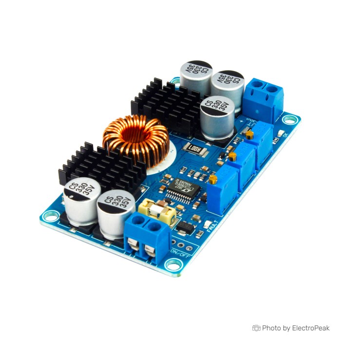
LTC3780 Automatic Buck Boost Power Supply Stabilizer Solar Charging Module
$11.7800
In stock
SKU
BAT-02-097
Volume discounts:
- +25 3 % $11.3900
- +50 5 % $11.1900
- +100 7 % $10.9900
- +300 8 % $10.8000
- +500 10 % $10.6000
Ships in 2-3 business days, then:
Free delivery in 12-15 days by Tracked Economic Shipping on orders over $100.
Free delivery in 7-10 days by Express Shipping on orders over $300.
More shipping info

Shop with confidence Learn More
 DC-DC Buck Step Down Module 6-24V to 5V 3A USB Charger Module Previous
LTC3780 Buck-Boost Module Overview
This LTC3780 buck-boost converter is an adjustable DC-DC power supply module that steps DC voltages up or down. Built for variable DC sources, it accepts an input of 5V to 32V and provides an adjustable output between 1V and 30V. Constant-current and constant-voltage (CC/CV) control suit makers working with lead-acid battery charging, high-power LED arrays, vehicle power stabilization, and custom bench supplies in our broader selection of DC-DC regulator modules.
The module steps voltage up or down as operating conditions change, keeping the output voltage steady when an unregulated input moves above or below your target. Setup matters. Tune the output voltage and current limits with a multimeter before connecting a load. The board has no onboard reverse-polarity protection, and high-power setups need deliberate thermal management. For similar open-frame stock, another adjustable CV/CC buck-boost module provides comparable step-up and step-down functions.
Specifications of LTC3780 Automatic Buck Boost Power Supply Stabilizer Solar Charging Module
- Input Voltage: DC 5-32V
- Recommended Input Voltage: Above 10V
- Output Voltage: DC 1V-30V
- Output Voltage: Continuously adjustable
- Output Voltage: Default 12V
- Output Current: 10A (MAX)
- Output Current: 7A long term
- Output Current: Default 4A
- Output Power: 80W
- Output Power: Peak 130W
- Output Ripple: 50mV
- Output Ripple Condition: 12V to 12V, 5A measured
- Input Reverse Polarity Protection: None
- Output Reverse Connection Protection: None
- Operating Temperature Range: -45 to +85 °C
- Size: 77.6 x 46.5 x 15 mm
- Short Circuit Protection: Yes
LTC3780 Buck-Boost Module Specifications Explained
Selecting a buck boost converter means translating its electrical thresholds into operating limits. The wide 5V to 32V input and 1V to 30V output cover automotive battery swings, fluctuating solar strings, and general DC-DC conversion. Dependable regulation still depends on operating margins and heat dissipation.
| Specification | Value | Why It Matters |
|---|---|---|
| Input Voltage Range | DC 5-32V (Recommended: >10V) | Allows operation across common 12V and 24V systems. Staying above the 10V recommendation ensures optimal switching behavior and full rated current delivery without stressing input stages. |
| Output Voltage Range | DC 1V-30V (Default: 12V) | Continuously adjustable via onboard trimpot. The factory preset is 12V, meaning you must measure and re-tune the trimmer before powering lower-voltage logic or sensitive electronics. |
| Output Current | 10A (MAX) / 7A long term | While the switching hardware can hit 10A briefly, system designs should use 7A as the continuous maximum to avoid thermal runaway. |
| Output Power | 80W continuous / Peak 130W | 80W represents the standard operating target under ambient convection. Delivering up to the 130W peak requires external active cooling and careful temperature monitoring. |
| Output Ripple | 50mV (at 12V to 12V, 5A measured) | Provides a baseline noise figure under matched 12V input/output loading. Ripple will vary depending on your specific input-to-output voltage differential and load current. |
| Physical Size | 77.6 x 46.5 x 15 mm | A compact footprint suitable for integration into vehicle enclosures or modular power cases, though sufficient open air clearance around the heatsink is required. |
For applications that only step down a higher-voltage source and need significantly more capacity, consider higher-power DC-DC regulator options. A dedicated high-power buck converter avoids buck-boost switching overhead entirely.
LTC3780 Solar Charging and CC/CV Setup
Although often described as a solar charging module, this board is an adjustable analog CC/CV converter rather than a full solar controller. It does not perform digital Maximum Power Point Tracking (MPPT). Instead, it provides continuous step-up/step-down regulation with an adjustable under-voltage cutoff potentiometer. This prevents an unregulated source—such as a solar array—from collapsing below a set voltage.
The module is listed as suitable for lead-acid battery charging, with bulk CC and absorption CV stages manually dialed in. It also operates as a standalone power supply without a battery attached; a battery is only necessary when battery charging is your specific objective. For multi-cell lithium batteries, such as Li-ion or LiFePO4, this board does not provide cell balancing, temperature cutoff, or chemistry-specific termination profiles. Using it with lithium packs requires an external battery management system (BMS) with proper safety cutoffs.
To configure the board for CC/CV charging or constant-current loads:
- Connect your input power source, ensuring the input voltage is at least 10V to establish stable control.
- Set the under-voltage protection potentiometer so the board protects your power source from excessive voltage drop.
- With no load connected, measure the output terminals with a multimeter and adjust the voltage potentiometer to your target float or operating voltage.
- Connect an ammeter across the output, or through a test load, and adjust the constant-current potentiometer to set your maximum current limit.
- Disconnect test meters, attach your battery or constant-current load, and monitor module temperatures during initial operation.
Check operating voltages carefully when selecting a solar input source: a nominal 6V panel falls well below the module's recommended 10V operating threshold and will not deliver optimal performance. For complete photovoltaic installations that require an enclosed chassis and automated multi-stage profiles, choose a dedicated solar charge controller.
LTC3780 FAULT LED and First-Power Test
Before wiring delicate loads, perform a bench verification. This hardware-adjusted analog module requires no software, drivers, or microcontrollers. Its onboard status indicators still need to be understood to avoid confusion during setup.
- Verify Input Polarity: Confirm that the input leads match the terminal markings. Connect a DC supply between 10V and 32V.
- Check Status Indicators: If the red FAULT LED illuminates and no output is present, the under-voltage (UV) threshold is set higher than your applied input voltage. Adjust the UV trimpot until the FAULT light extinguishes and the normal output indicator illuminates.
- Set Output Voltage: Place multimeter probes across the output terminals. Rotate the voltage trimpot until your exact operating voltage appears. Do not rely on the factory 12V default.
- Establish Current Limit: Using an inline ammeter, adjust the current limit trimpot to match the safe charging or operating current of your load.
- Attach Load: Remove test meters, connect the final circuit, and verify that the module remains within thermal limits under load.
For modular wiring on high-current battery setups, removable DC connector hardware such as XT60 pairs can help prevent accidental reversed shorts during bench work.
LTC3780 Buck-Boost Module Limitations and Thermal Use
Understanding the LTC3780 buck boost module's hardware constraints helps prevent board failures and unverified operating expectations.
- Zero Reverse-Polarity Protection: Neither the input nor the output has reverse-polarity protection. A reversed connection will damage the switching circuitry immediately. Install a high-current Schottky diode in series with the input, and place another diode on the output if connecting to an active battery.
- External Fusing Required: Component populations vary between production batches, and an onboard input fuse cannot be assumed. Always install an external inline fuse matched to your supply wire gauge and expected current draw.
- Realistic Thermal Envelopes: While 10A and 130W peak figures are specified, plan continuous operation around 7A and 80W. Pushing beyond 80W without forced-air fan cooling or larger external heatsinks will lead to thermal throttling or component stress.
- Protections Do Not Prevent Miswiring: The onboard short-circuit, over-voltage, and overload protections guard the switching stages during normal operation, but they do not protect against crossed input wires or reverse battery feedback.
- Batch Variances: As generic-ecosystem hardware, the board can vary between manufacturing runs in passive components, trimpot sensitivity, and heatsink mounting. Always measure electrical values on your specific board before deployment.
Need an all-in-one bench solution with an integrated display and active cooling already mounted? Consider a display-equipped buck-boost module instead.
LTC3780 vs Adjustable Buck-Boost Power Modules
If your design requires higher operating current, step-down conversion only, or built-in digital parameter readouts, another DC-DC module may better match your enclosure and thermal plans.
| Model | Topology | Input Voltage | Output Voltage | Max Ratings | Display & Cooling | Target Use Case |
|---|---|---|---|---|---|---|
| LTC3780 Module | Buck-Boost | 5–32V (Rec: >10V) | 1–30V | 10A max (7A long term) / 80W (130W peak) | LED indicators only; passive heatsink | Compact analog CC/CV regulation, lead-acid charging, vehicle stabilization |
| ZK-DP60 | Buck-Boost | 5.5–30V | 0.5–30V | 6A max (with fan) / 60W max | Integrated LCD; built-in cooling fan | Low-power bench testing and monitoring where built-in readouts save panel space |
| AP-D5830A | Buck (Step-Down Only) | 20–70V | 2.5–58V | 30A max / 800W max | No display; radiator with temp-controlled fan | High-current industrial or robotics setups where input voltage is always higher than output |
| ZK-SJ30 | Buck-Boost | 6–80V | 1.3–78V | 30A max / 700W max | Integrated digital display; MPPT adjustment knob | High-voltage, high-current solar setups requiring direct parameter readouts |
Start with voltage topology when choosing among these modules. The LTC3780 handles bidirectional crossing when the input can swing above or below the load target. Where high-power step-down duty is required, a high-power buck converter avoids buck-boost switching losses. For high-voltage, high-power regulation with panel readouts, a high-power buck-boost module supports higher electrical limits.
LTC3780 Buck-Boost Module FAQ
Can the LTC3780 module work without a battery?
Yes. The module works as a standard CC/CV DC power supply without a battery. You can connect it directly to resistive loads, microcontrollers, or motors within its voltage and current ratings; a battery is only necessary when battery charging is your project goal.
Is this LTC3780 solar charging module a true MPPT controller?
No, it is an analog CC/CV buck-boost regulator rather than a true MPPT controller. Its under-voltage potentiometer can prevent a panel from collapsing under load, but it does not dynamically sweep or track the maximum power point. For complete photovoltaic installations, use a dedicated solar charge controller.
Can I run this LTC3780 module at 10A continuously?
No. The 10A rating is a maximum ceiling rather than a continuous target. Plan continuous operation around 7A long-term and 80W total power. Operating above 80W or near peak currents requires active cooling and thermal monitoring.
Does the LTC3780 board have reverse-polarity protection?
No, there is no reverse-polarity protection on the input or reverse-connection protection on the output. Reversing positive and negative leads will destroy the module. You must wire an external Schottky diode and inline fuse on the input, as well as an output diode when connecting batteries.
Why is the LTC3780 FAULT LED on with no output?
The FAULT LED turns on when the input voltage is below the configured under-voltage threshold. Rotate the under-voltage trimpot counter-clockwise to lower the threshold until the indicator turns off and normal output resumes.
Can this module charge LiFePO4 or lithium-ion batteries?
Not as a complete standalone solution. The board is specified for lead-acid charging and lacks cell balancing, over-temperature protection, and lithium-specific termination logic. Connecting cells such as an 18650 lithium battery requires a dedicated battery management system (BMS) between the board and the cells.
Does this LTC3780 module have a display?
No, this board uses analog potentiometers and status LEDs without a digital readout. Measure voltage and current with a multimeter during setup. If you need onboard voltage and current displays, choose a display-equipped buck-boost module.
Is there an equivalent alternative if this board is unavailable?
Yes, another adjustable CV/CC buck-boost module provides similar wide-range step-up and step-down DC conversion for bench setups and LED driving.
Purchase Decision Summary
- Ideal for: Makers who need an adjustable 5–32V input to 1–30V output CC/CV buck-boost converter for lead-acid battery maintenance, constant-current LED driving, vehicle 12V stabilization, or general DC bench experiments using manual meter adjustments.
- Maybe for: Basic solar-to-battery setups where you can supply your own reverse-polarity diodes, inline fusing, cooling fan, and manual voltage tuning.
- Consider another option if: Your application requires plug-and-play lithium multi-stage charging, genuine dynamic MPPT solar tracking, built-in reverse-polarity protection, integrated LCD readouts, or continuous loads exceeding 7A / 80W without custom heatsinking.
Buying Checklist
- Confirm your DC source provides between 5V and 32V (recommended above 10V).
- Ensure the required output is between 1V and 30V and continuously adjustable.
- Size continuous loads around 7A long term and 80W total power.
- Have a multimeter ready to measure and set output voltage before connecting loads.
- Have an ammeter ready to adjust the constant-current potentiometer.
- Source an external inline fuse and an input Schottky diode for reverse-polarity defense.
- Source an output blocking diode if connecting to a battery or live DC bus.
- Provide a fan or active ventilation if planning to draw more than 80W.
- Verify that your enclosure accommodates the 77.6 x 46.5 x 15 mm board dimensions.
Write Your Own Review

Please complete your information below to login.
Sign In
Create New Account