
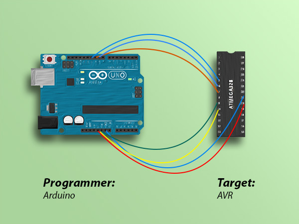
Are you looking to burn a bootloader and program AVR microcontrollers easily and efficiently? In this tutorial, we will guide you through the process using an Arduino Uno board and the Arduino IDE software. By utilizing the In-circuit Serial Programmer (ISP) feature of an Arduino Board, you can quickly install the bootloader and program various AVR microcontrollers.
Overview
There has definitely been times that:
- Your microcontroller IC has been burnt
- Or you have obtained a new microcontroller and are willing to program it in the simplest way with the shortest time
However, before doing that, you need to have bootloader burnt on your microcontroller. When you buy a new microcontroller, you can’t just connect it to your computer and program it using a UBS to TTL converter. First, you need to install the bootloader on your microcontroller through the ISP pins, and then you will be able to upload your desired code to it using a USB to TTL converter.
We can use the ISP (In-circuit Serial Programmer) of an Arduino Board for installing the bootloader and also programming different AVR microcontrollers.
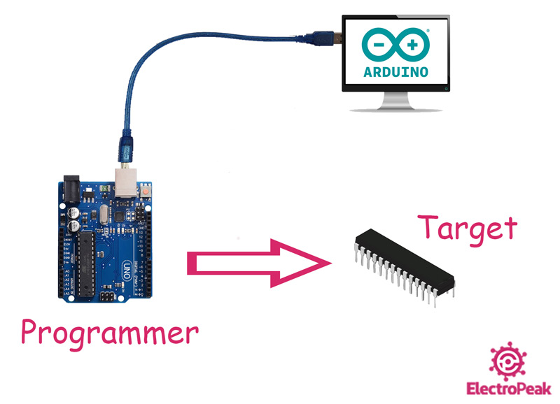
In this comprehensive tutorial, we are going to burn the bootloader on an AVR microcontroller and program it using an Arduino Uno Board and the Arduino IDE software. We will actually use the Arduino Uno as an ISP programmer.
Note
Most of the Arduino Boards come with an AVR microcontroller. So we can do the same thing between two Arduino Boards. We can use one as an ISP programmer and the other as the target. If you want to know more about this, you can check this link.
What You Will Learn
In this tutorial, we want to show you how you can program a new AVR microcontroller using an Arduino Uno board and the Arduino IDE. For that, we first burn a bootloader on the AVR microcontroller using the Arduino Board. Then, we will program the microcontroller with a simple code. So, we will be covering all steps needed to program a new AVR microcontroller using an Arduino Board.
By the end of this tutorial, you will be proficient in burning bootloaders and programming AVR microcontrollers using an Arduino board.
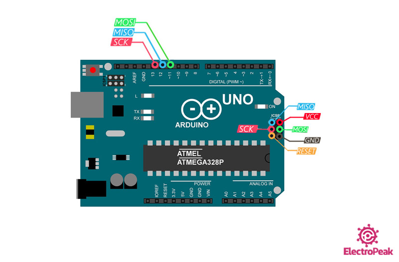
Arduino Uno Board Pinout as an ISP Programmer
One of the easiest ways of programming an AVR microcontroller is to use the ISP pins of an Arduino Board. The ISP pins of an Arduino Board make it possible for us to use the Arduino Board as an ISP programmer. These pins can be accessed in two ways:
- Pins 11, 12, and 13 on the Arduino Uno board (note that the pin numbers may vary for different Arduino boards).
- The ISP connector (having 6 pins) which is directly usable.
The 6 pins of the ISP are as follows:
- VCC: 5V
- GND: Electrical ground
- MOSI: Data line from the Master to the Slave
- MISO: Data line from the Slave to the Master
- SCK: Clock pin
- RESET: Reset pin
Note
The 3 pins 11, 12 and 13 are usually used when using the Arduino Board as the programmer. And, the ISP connector is used if we want to program the Arduino Board.
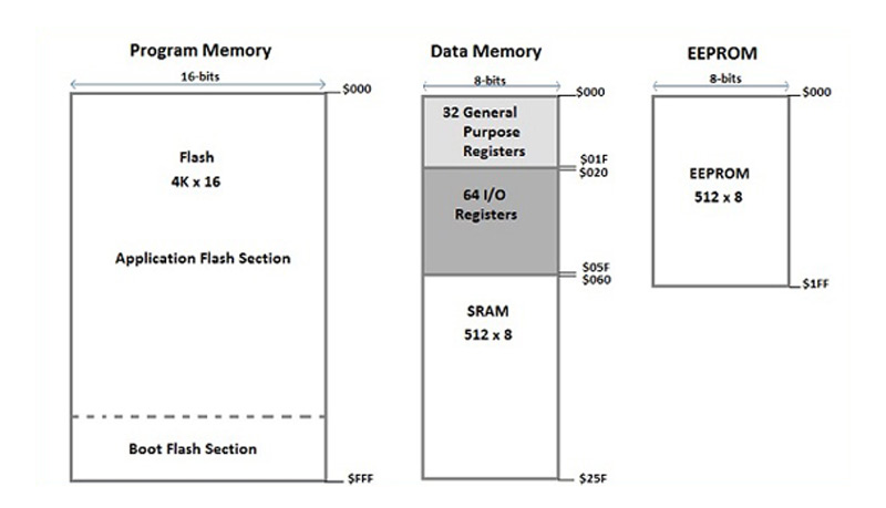
What is a Bootloader?
As mentioned earlier, a new AVR microcontroller cannot be programmed using USB to TTL adapters. To program it in that way, we need to first burn a program named “Bootloader” on it and then, they can be programmed using a USB to TTL converter. Once the bootloader is burnt on the AVR microcontroller, you can upload your desired codes on it using the Arduino IDE.
The volume of this program is about 512B and is stored at the end of the Flash memory. This program is executed again each time the microcontroller is reset. For example, the Atmega8 microcontroller has an 8 KB flash memory. This memory is divided into 2 parts. The end of this memory belongs to the bootloader program, and the rest is used to store other programs that are uploaded. The image below is a representation of the Flash, SRAM and EEPROM memories of the Atmega8 microcontroller.
Different Types of AVR Microcontrollers
AVR microcontroller are manufactured in various sizes and number of pins. Generally, they can be divided into the 5 following categories:
- MighyCore
- MegaCore
- MegaCoreX
- MiniCore
- MicroCore
If you want to know more about each of the AVR microcontroller categories above, click here.
The Atmega8 microcontroller belongs to the MiniCore family. These microcontrollers have a total of 28 pins. The pinout of the microcontrollers in the MiniCore series is as follows:

To install the bootloader on an AVR microcontroller and program it, we need some information regarding its pinout:
- 1- These pins are used for burning the bootloader on the microcontroller.
- 2- The microcontroller power supply pins -GND and VCC-
- 3- These 2 pins are for connecting the external crystal to set the operating frequency of the microcontroller
- 4- The RX and TX pins for programming the microcontroller using a USB to TTL converter.
Note that the same pins are used for all AVR microcontrollers. They only might have different pin numbers in different microcontrollers.
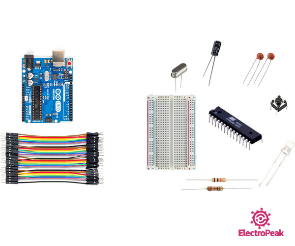
Required Material
We are going to complete this tutorial on the Atmega8 microcontroller from the AVR microcontroller series. To program this microcontroller properly, some other components are also used. These components are necessary for the proper functioning of the whole process. Here is the list you need:
Hardware Components
Software Apps
Burn Bootloader on an AVR Microcontroller
Step 1: Arduino as an ISP Programmer
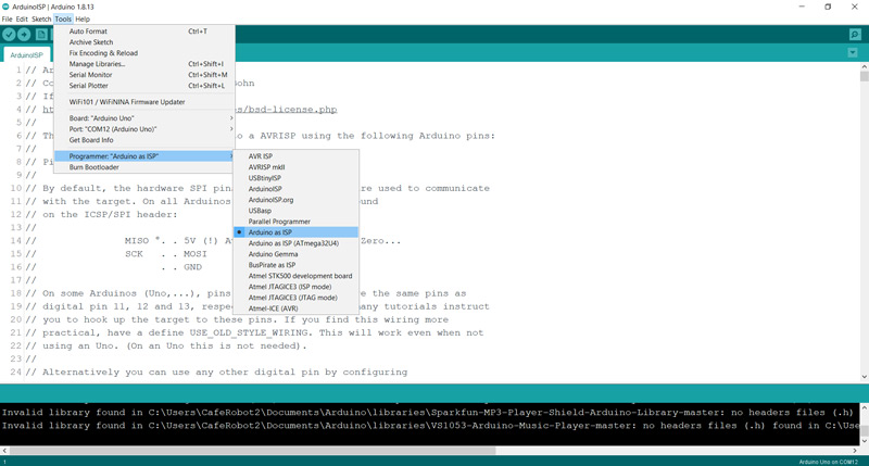
We want to use an Arduino Uno board as a programmer. For that, we first choose the right board and port from the “tools” menu in the Arduino IDE.

In the same menu and in the “Programmer” section, we choose the “Arduino as ISP” option.
Now, we go to “Files → Examples” and open the “ArduinoISP”.
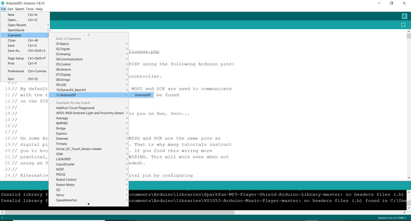
The following code will appear. Upload it on your Arduino board:
/*
  Made on 18 may 2021
  Home
  based on Arduino Library
*/
// ArduinoISP
// Copyright (c) 2008-2011 Randall Bohn
// If you require a license, see
// http://www.opensource.org/licenses/bsd-license.php
//
// This sketch turns the Arduino into a AVRISP using the following Arduino pins:
//
// Pin 10 is used to reset the target microcontroller.
//
// By default, the hardware SPI pins MISO, MOSI and SCK are used to communicate
// with the target. On all Arduinos, these pins can be found
// on the ICSP/SPI header:
//
//               MISO °. . 5V (!) Avoid this pin on Due, Zero...
//               SCK   . . MOSI
//                     . . GND
//
// On some Arduinos (Uno,...), pins MOSI, MISO and SCK are the same pins as
// digital pin 11, 12 and 13, respectively. That is why many tutorials instruct
// you to hook up the target to these pins. If you find this wiring more
// practical, have a define USE_OLD_STYLE_WIRING. This will work even when not
// using an Uno. (On an Uno this is not needed).
//
// Alternatively you can use any other digital pin by configuring
// software ('BitBanged') SPI and having appropriate defines for PIN_MOSI,
// PIN_MISO and PIN_SCK.
//
// IMPORTANT: When using an Arduino that is not 5V tolerant (Due, Zero, ...) as
// the programmer, make sure to not expose any of the programmer's pins to 5V.
// A simple way to accomplish this is to power the complete system (programmer
// and target) at 3V3.
//
// Put an LED (with resistor) on the following pins:
// 9: Heartbeat   - shows the programmer is running
// 8: Error       - Lights up if something goes wrong (use red if that makes sense)
// 7: Programming - In communication with the slave
//

#include "Arduino.h"
#undef SERIAL


#define PROG_FLICKER true

// Configure SPI clock (in Hz).
// E.g. for an ATtiny @ 128 kHz: the datasheet states that both the high and low
// SPI clock pulse must be > 2 CPU cycles, so take 3 cycles i.e. divide target
// f_cpu by 6:
//     #define SPI_CLOCK            (128000/6)
//
// A clock slow enough for an ATtiny85 @ 1 MHz, is a reasonable default:

#define SPI_CLOCK 		(1000000/6)


// Select hardware or software SPI, depending on SPI clock.
// Currently only for AVR, for other architectures (Due, Zero,...), hardware SPI
// is probably too fast anyway.

#if defined(ARDUINO_ARCH_AVR)

#if SPI_CLOCK > (F_CPU / 128)
#define USE_HARDWARE_SPI
#endif

#endif

// Configure which pins to use:

// The standard pin configuration.
#ifndef ARDUINO_HOODLOADER2

#define RESET     10 // Use pin 10 to reset the target rather than SS
#define LED_HB    9
#define LED_ERR   8
#define LED_PMODE 7

// Uncomment following line to use the old Uno style wiring
// (using pin 11, 12 and 13 instead of the SPI header) on Leonardo, Due...

// #define USE_OLD_STYLE_WIRING

#ifdef USE_OLD_STYLE_WIRING

#define PIN_MOSI	11
#define PIN_MISO	12
#define PIN_SCK		13

#endif

// HOODLOADER2 means running sketches on the ATmega16U2 serial converter chips
// on Uno or Mega boards. We must use pins that are broken out:
#else

#define RESET     	4
#define LED_HB    	7
#define LED_ERR   	6
#define LED_PMODE 	5

#endif

// By default, use hardware SPI pins:
#ifndef PIN_MOSI
#define PIN_MOSI 	MOSI
#endif

#ifndef PIN_MISO
#define PIN_MISO 	MISO
#endif

#ifndef PIN_SCK
#define PIN_SCK 	SCK
#endif

// Force bitbanged SPI if not using the hardware SPI pins:
#if (PIN_MISO != MISO) ||  (PIN_MOSI != MOSI) || (PIN_SCK != SCK)
#undef USE_HARDWARE_SPI
#endif


// Configure the serial port to use.
//
// Prefer the USB virtual serial port (aka. native USB port), if the Arduino has one:
//   - it does not autoreset (except for the magic baud rate of 1200).
//   - it is more reliable because of USB handshaking.
//
// Leonardo and similar have an USB virtual serial port: 'Serial'.
// Due and Zero have an USB virtual serial port: 'SerialUSB'.
//
// On the Due and Zero, 'Serial' can be used too, provided you disable autoreset.
// To use 'Serial': #define SERIAL Serial

#ifdef SERIAL_PORT_USBVIRTUAL
#define SERIAL SERIAL_PORT_USBVIRTUAL
#else
#define SERIAL Serial
#endif


// Configure the baud rate:

#define BAUDRATE	19200
// #define BAUDRATE	115200
// #define BAUDRATE	1000000


#define HWVER 2
#define SWMAJ 1
#define SWMIN 18

// STK Definitions
#define STK_OK      0x10
#define STK_FAILED  0x11
#define STK_UNKNOWN 0x12
#define STK_INSYNC  0x14
#define STK_NOSYNC  0x15
#define CRC_EOP     0x20 //ok it is a space...

void pulse(int pin, int times);

#ifdef USE_HARDWARE_SPI
#include "SPI.h"
#else

#define SPI_MODE0 0x00

class SPISettings {
  public:
    // clock is in Hz
    SPISettings(uint32_t clock, uint8_t bitOrder, uint8_t dataMode) : clock(clock) {
      (void) bitOrder;
      (void) dataMode;
    };

  private:
    uint32_t clock;

    friend class BitBangedSPI;
};

class BitBangedSPI {
  public:
    void begin() {
      digitalWrite(PIN_SCK, LOW);
      digitalWrite(PIN_MOSI, LOW);
      pinMode(PIN_SCK, OUTPUT);
      pinMode(PIN_MOSI, OUTPUT);
      pinMode(PIN_MISO, INPUT);
    }

    void beginTransaction(SPISettings settings) {
      pulseWidth = (500000 + settings.clock - 1) / settings.clock;
      if (pulseWidth == 0)
        pulseWidth = 1;
    }

    void end() {}

    uint8_t transfer (uint8_t b) {
      for (unsigned int i = 0; i < 8; ++i) {
        digitalWrite(PIN_MOSI, (b & 0x80) ? HIGH : LOW);
        digitalWrite(PIN_SCK, HIGH);
        delayMicroseconds(pulseWidth);
        b = (b << 1) | digitalRead(PIN_MISO);
        digitalWrite(PIN_SCK, LOW); // slow pulse
        delayMicroseconds(pulseWidth);
      }
      return b;
    }

  private:
    unsigned long pulseWidth; // in microseconds
};

static BitBangedSPI SPI;

#endif

void setup() {
  SERIAL.begin(BAUDRATE);

  pinMode(LED_PMODE, OUTPUT);
  pulse(LED_PMODE, 2);
  pinMode(LED_ERR, OUTPUT);
  pulse(LED_ERR, 2);
  pinMode(LED_HB, OUTPUT);
  pulse(LED_HB, 2);

}

int error = 0;
int pmode = 0;
// address for reading and writing, set by 'U' command
unsigned int here;
uint8_t buff[256]; // global block storage

#define beget16(addr) (*addr * 256 + *(addr+1) )
typedef struct param {
  uint8_t devicecode;
  uint8_t revision;
  uint8_t progtype;
  uint8_t parmode;
  uint8_t polling;
  uint8_t selftimed;
  uint8_t lockbytes;
  uint8_t fusebytes;
  uint8_t flashpoll;
  uint16_t eeprompoll;
  uint16_t pagesize;
  uint16_t eepromsize;
  uint32_t flashsize;
}
parameter;

parameter param;

// this provides a heartbeat on pin 9, so you can tell the software is running.
uint8_t hbval = 128;
int8_t hbdelta = 8;
void heartbeat() {
  static unsigned long last_time = 0;
  unsigned long now = millis();
  if ((now - last_time) < 40)
    return;
  last_time = now;
  if (hbval > 192) hbdelta = -hbdelta;
  if (hbval < 32) hbdelta = -hbdelta;
  hbval += hbdelta;
  analogWrite(LED_HB, hbval);
}

static bool rst_active_high;

void reset_target(bool reset) {
  digitalWrite(RESET, ((reset && rst_active_high) || (!reset && !rst_active_high)) ? HIGH : LOW);
}

void loop(void) {
  // is pmode active?
  if (pmode) {
    digitalWrite(LED_PMODE, HIGH);
  } else {
    digitalWrite(LED_PMODE, LOW);
  }
  // is there an error?
  if (error) {
    digitalWrite(LED_ERR, HIGH);
  } else {
    digitalWrite(LED_ERR, LOW);
  }

  // light the heartbeat LED
  heartbeat();
  if (SERIAL.available()) {
    avrisp();
  }
}

uint8_t getch() {
  while (!SERIAL.available());
  return SERIAL.read();
}
void fill(int n) {
  for (int x = 0; x < n; x++) {
    buff[x] = getch();
  }
}

#define PTIME 30
void pulse(int pin, int times) {
  do {
    digitalWrite(pin, HIGH);
    delay(PTIME);
    digitalWrite(pin, LOW);
    delay(PTIME);
  } while (times--);
}

void prog_lamp(int state) {
  if (PROG_FLICKER) {
    digitalWrite(LED_PMODE, state);
  }
}

uint8_t spi_transaction(uint8_t a, uint8_t b, uint8_t c, uint8_t d) {
  SPI.transfer(a);
  SPI.transfer(b);
  SPI.transfer(c);
  return SPI.transfer(d);
}

void empty_reply() {
  if (CRC_EOP == getch()) {
    SERIAL.print((char)STK_INSYNC);
    SERIAL.print((char)STK_OK);
  } else {
    error++;
    SERIAL.print((char)STK_NOSYNC);
  }
}

void breply(uint8_t b) {
  if (CRC_EOP == getch()) {
    SERIAL.print((char)STK_INSYNC);
    SERIAL.print((char)b);
    SERIAL.print((char)STK_OK);
  } else {
    error++;
    SERIAL.print((char)STK_NOSYNC);
  }
}

void get_version(uint8_t c) {
  switch (c) {
    case 0x80:
      breply(HWVER);
      break;
    case 0x81:
      breply(SWMAJ);
      break;
    case 0x82:
      breply(SWMIN);
      break;
    case 0x93:
      breply('S'); // serial programmer
      break;
    default:
      breply(0);
  }
}

void set_parameters() {
  // call this after reading parameter packet into buff[]
  param.devicecode = buff[0];
  param.revision   = buff[1];
  param.progtype   = buff[2];
  param.parmode    = buff[3];
  param.polling    = buff[4];
  param.selftimed  = buff[5];
  param.lockbytes  = buff[6];
  param.fusebytes  = buff[7];
  param.flashpoll  = buff[8];
  // ignore buff[9] (= buff[8])
  // following are 16 bits (big endian)
  param.eeprompoll = beget16(&buff[10]);
  param.pagesize   = beget16(&buff[12]);
  param.eepromsize = beget16(&buff[14]);

  // 32 bits flashsize (big endian)
  param.flashsize = buff[16] * 0x01000000
                    + buff[17] * 0x00010000
                    + buff[18] * 0x00000100
                    + buff[19];

  // AVR devices have active low reset, AT89Sx are active high
  rst_active_high = (param.devicecode >= 0xe0);
}

void start_pmode() {

  // Reset target before driving PIN_SCK or PIN_MOSI

  // SPI.begin() will configure SS as output, so SPI master mode is selected.
  // We have defined RESET as pin 10, which for many Arduinos is not the SS pin.
  // So we have to configure RESET as output here,
  // (reset_target() first sets the correct level)
  reset_target(true);
  pinMode(RESET, OUTPUT);
  SPI.begin();
  SPI.beginTransaction(SPISettings(SPI_CLOCK, MSBFIRST, SPI_MODE0));

  // See AVR datasheets, chapter "SERIAL_PRG Programming Algorithm":

  // Pulse RESET after PIN_SCK is low:
  digitalWrite(PIN_SCK, LOW);
  delay(20); // discharge PIN_SCK, value arbitrarily chosen
  reset_target(false);
  // Pulse must be minimum 2 target CPU clock cycles so 100 usec is ok for CPU
  // speeds above 20 KHz
  delayMicroseconds(100);
  reset_target(true);

  // Send the enable programming command:
  delay(50); // datasheet: must be > 20 msec
  spi_transaction(0xAC, 0x53, 0x00, 0x00);
  pmode = 1;
}

void end_pmode() {
  SPI.end();
  // We're about to take the target out of reset so configure SPI pins as input
  pinMode(PIN_MOSI, INPUT);
  pinMode(PIN_SCK, INPUT);
  reset_target(false);
  pinMode(RESET, INPUT);
  pmode = 0;
}

void universal() {
  uint8_t ch;

  fill(4);
  ch = spi_transaction(buff[0], buff[1], buff[2], buff[3]);
  breply(ch);
}

void flash(uint8_t hilo, unsigned int addr, uint8_t data) {
  spi_transaction(0x40 + 8 * hilo,
                  addr >> 8 & 0xFF,
                  addr & 0xFF,
                  data);
}
void commit(unsigned int addr) {
  if (PROG_FLICKER) {
    prog_lamp(LOW);
  }
  spi_transaction(0x4C, (addr >> 8) & 0xFF, addr & 0xFF, 0);
  if (PROG_FLICKER) {
    delay(PTIME);
    prog_lamp(HIGH);
  }
}

unsigned int current_page() {
  if (param.pagesize == 32) {
    return here & 0xFFFFFFF0;
  }
  if (param.pagesize == 64) {
    return here & 0xFFFFFFE0;
  }
  if (param.pagesize == 128) {
    return here & 0xFFFFFFC0;
  }
  if (param.pagesize == 256) {
    return here & 0xFFFFFF80;
  }
  return here;
}


void write_flash(int length) {
  fill(length);
  if (CRC_EOP == getch()) {
    SERIAL.print((char) STK_INSYNC);
    SERIAL.print((char) write_flash_pages(length));
  } else {
    error++;
    SERIAL.print((char) STK_NOSYNC);
  }
}

uint8_t write_flash_pages(int length) {
  int x = 0;
  unsigned int page = current_page();
  while (x < length) {
    if (page != current_page()) {
      commit(page);
      page = current_page();
    }
    flash(LOW, here, buff[x++]);
    flash(HIGH, here, buff[x++]);
    here++;
  }

  commit(page);

  return STK_OK;
}

#define EECHUNK (32)
uint8_t write_eeprom(unsigned int length) {
  // here is a word address, get the byte address
  unsigned int start = here * 2;
  unsigned int remaining = length;
  if (length > param.eepromsize) {
    error++;
    return STK_FAILED;
  }
  while (remaining > EECHUNK) {
    write_eeprom_chunk(start, EECHUNK);
    start += EECHUNK;
    remaining -= EECHUNK;
  }
  write_eeprom_chunk(start, remaining);
  return STK_OK;
}
// write (length) bytes, (start) is a byte address
uint8_t write_eeprom_chunk(unsigned int start, unsigned int length) {
  // this writes byte-by-byte, page writing may be faster (4 bytes at a time)
  fill(length);
  prog_lamp(LOW);
  for (unsigned int x = 0; x < length; x++) {
    unsigned int addr = start + x;
    spi_transaction(0xC0, (addr >> 8) & 0xFF, addr & 0xFF, buff[x]);
    delay(45);
  }
  prog_lamp(HIGH);
  return STK_OK;
}

void program_page() {
  char result = (char) STK_FAILED;
  unsigned int length = 256 * getch();
  length += getch();
  char memtype = getch();
  // flash memory @here, (length) bytes
  if (memtype == 'F') {
    write_flash(length);
    return;
  }
  if (memtype == 'E') {
    result = (char)write_eeprom(length);
    if (CRC_EOP == getch()) {
      SERIAL.print((char) STK_INSYNC);
      SERIAL.print(result);
    } else {
      error++;
      SERIAL.print((char) STK_NOSYNC);
    }
    return;
  }
  SERIAL.print((char)STK_FAILED);
  return;
}

uint8_t flash_read(uint8_t hilo, unsigned int addr) {
  return spi_transaction(0x20 + hilo * 8,
                         (addr >> 8) & 0xFF,
                         addr & 0xFF,
                         0);
}

char flash_read_page(int length) {
  for (int x = 0; x < length; x += 2) {
    uint8_t low = flash_read(LOW, here);
    SERIAL.print((char) low);
    uint8_t high = flash_read(HIGH, here);
    SERIAL.print((char) high);
    here++;
  }
  return STK_OK;
}

char eeprom_read_page(int length) {
  // here again we have a word address
  int start = here * 2;
  for (int x = 0; x < length; x++) {
    int addr = start + x;
    uint8_t ee = spi_transaction(0xA0, (addr >> 8) & 0xFF, addr & 0xFF, 0xFF);
    SERIAL.print((char) ee);
  }
  return STK_OK;
}

void read_page() {
  char result = (char)STK_FAILED;
  int length = 256 * getch();
  length += getch();
  char memtype = getch();
  if (CRC_EOP != getch()) {
    error++;
    SERIAL.print((char) STK_NOSYNC);
    return;
  }
  SERIAL.print((char) STK_INSYNC);
  if (memtype == 'F') result = flash_read_page(length);
  if (memtype == 'E') result = eeprom_read_page(length);
  SERIAL.print(result);
}

void read_signature() {
  if (CRC_EOP != getch()) {
    error++;
    SERIAL.print((char) STK_NOSYNC);
    return;
  }
  SERIAL.print((char) STK_INSYNC);
  uint8_t high = spi_transaction(0x30, 0x00, 0x00, 0x00);
  SERIAL.print((char) high);
  uint8_t middle = spi_transaction(0x30, 0x00, 0x01, 0x00);
  SERIAL.print((char) middle);
  uint8_t low = spi_transaction(0x30, 0x00, 0x02, 0x00);
  SERIAL.print((char) low);
  SERIAL.print((char) STK_OK);
}
//////////////////////////////////////////
//////////////////////////////////////////


////////////////////////////////////
////////////////////////////////////
void avrisp() {
  uint8_t ch = getch();
  switch (ch) {
    case '0': // signon
      error = 0;
      empty_reply();
      break;
    case '1':
      if (getch() == CRC_EOP) {
        SERIAL.print((char) STK_INSYNC);
        SERIAL.print("AVR ISP");
        SERIAL.print((char) STK_OK);
      }
      else {
        error++;
        SERIAL.print((char) STK_NOSYNC);
      }
      break;
    case 'A':
      get_version(getch());
      break;
    case 'B':
      fill(20);
      set_parameters();
      empty_reply();
      break;
    case 'E': // extended parameters - ignore for now
      fill(5);
      empty_reply();
      break;
    case 'P':
      if (!pmode)
        start_pmode();
      empty_reply();
      break;
    case 'U': // set address (word)
      here = getch();
      here += 256 * getch();
      empty_reply();
      break;

    case 0x60: //STK_PROG_FLASH
      getch(); // low addr
      getch(); // high addr
      empty_reply();
      break;
    case 0x61: //STK_PROG_DATA
      getch(); // data
      empty_reply();
      break;

    case 0x64: //STK_PROG_PAGE
      program_page();
      break;

    case 0x74: //STK_READ_PAGE 't'
      read_page();
      break;

    case 'V': //0x56
      universal();
      break;
    case 'Q': //0x51
      error = 0;
      end_pmode();
      empty_reply();
      break;

    case 0x75: //STK_READ_SIGN 'u'
      read_signature();
      break;

    // expecting a command, not CRC_EOP
    // this is how we can get back in sync
    case CRC_EOP:
      error++;
      SERIAL.print((char) STK_NOSYNC);
      break;

    // anything else we will return STK_UNKNOWN
    default:
      error++;
      if (CRC_EOP == getch())
        SERIAL.print((char)STK_UNKNOWN);
      else
        SERIAL.print((char)STK_NOSYNC);
  }
}
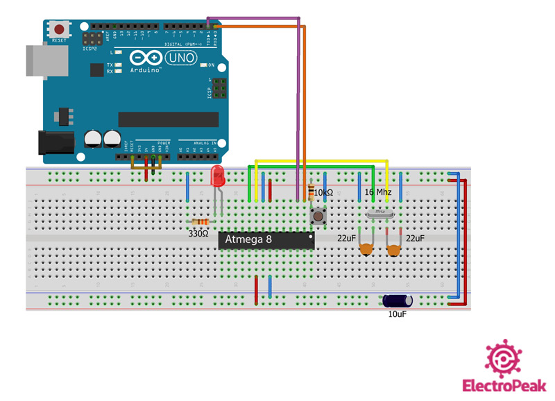
Step 2: Circuit
In this step, the microcontroller is connected to the required components on a breadboard and finally connected to the Arduino Board:
- The “RESET” pin is pulled-up using a 10K resistor.
- A 10 uF capacitor is put between the power supply pins (VCC and GND) to avoid noise and stabilize the supply voltage.
- The 2 pins of the crystal connected to the GND through 2 22pF capacitors
Note
The 2 capacitors used for the crystal can be between 18 – 22 pF.

Step 3: Adding the Target Microcontroller
Now, the circuit is ready, and we can add a microcontroller, so we can burn the bootloader on it. For that, we do as following:
- Step 1: First, check this Github link and find out the AVR category your microcontroller belong to. For example, ours is the Atmega8 and belong to the MiniCore category.
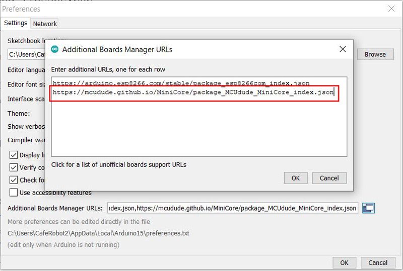
- Step 2: In the Github link above, go to “How to install” section and copy the link below:
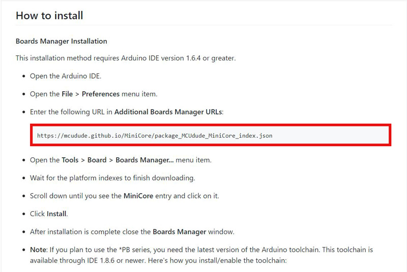
- Step 3: Open the Arduino IDE and open the “Preferences” in the “Files” menu. In the opened page, click on the “Additional Boards Manager URLs” and paste the link you copied in the previous step:
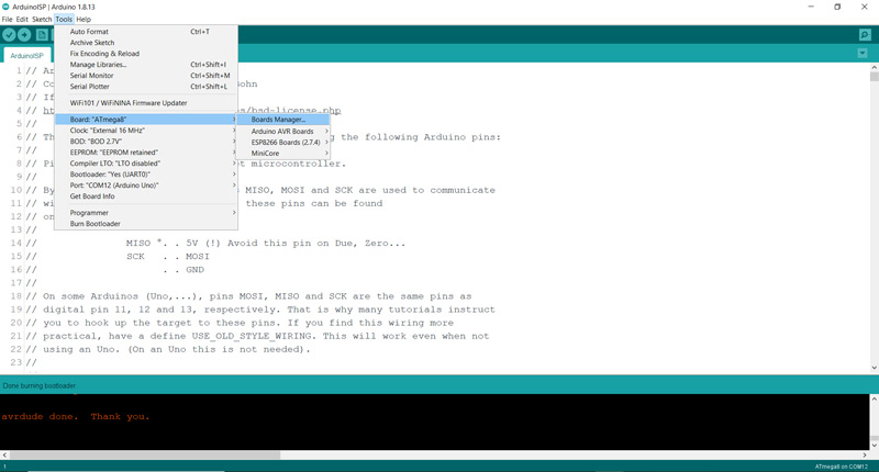
- Step 4: Go to “Tools → Board” and open the “Board Manager” icon.
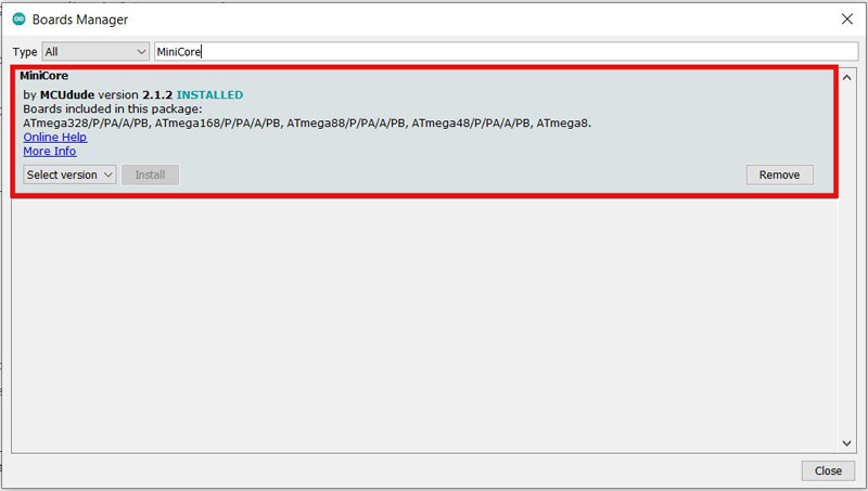
- Step 5: Wait until the downloading is completed. Then, search the word “MiniCore” and install it.
Note
You can repeat the same procedure for any other AVR microcontroller.
Step 4: Burn the Bootloader on the Target AVR Microcontroller
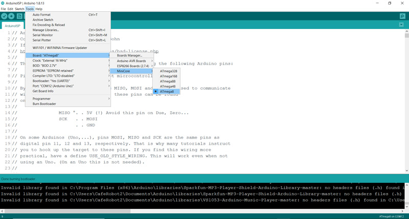
When the final circuit is ready, once again open the Arduino IDE, go to “Tools → Board” and open the MiniCore icon and choose your target microcontroller which is “Atmega8” in our case.
Finally, click on “Burn Bootloader” at the end of the “Tools” menu. Wait for the burning to complete. After properly doing the procedure above, the phrase “Done Burning Bootloader” will appear.

Note
In some applications, we need the whole memory to program the microcontroller. In such cases that the bootloader has been burnt on your microcontroller, and now you need the whole memory for your new code, write your desired code and instead of upload, go to the “Sketch” menu and click on “Upload Using Programmer”. This way, the bootloader is removed and the code you’ve uploaded will occupy as much space as it needs.
Program the Microcontroller
Once the bootloader is burnt on your microcontroller, the microcontroller is ready to be programmed using a USB to TTL adapter and the Arduino IDE. Now, we are going to upload a simple code on the microcontroller and test its performance.
For that, we can use the Arduino Board as our USB to TTL converter and program the microcontroller through the 2 RX and TX pins.
Step 1: Circuit
As already said, the 2 pins RX and TX are used for the communication between the microcontroller and the software. Pay attention that we should connect the RX and TX pins of the Arduino Board to the RX and TX pins of the microcontroller, respectively. We actually want to program the microcontroller using the USB to TTL adapter chip of the Arduino Board. To do that, we need to take the microcontroller of the Arduino Board out of the circuit. For that purpose, connect the “RESET” pin of the Arduino Board to the Ground.
We have connected an LED to pin 8 of the microcontroller, so we can test the programmer performance with a simple code.
Step 2: Programming the Microcontroller
After setting up the circuit, connect the Arduino Board to the computer again and check the settings in the “Tools” menu:
- In “Tools → Board”, choose Atmega8
- In “Tools → Port”, choose the port the Arduino Uno is connected to
To make sure everything has been done successfully up to now, we are going to upload a simple “Blink” code on the Atmega8 microcontroller and see the results.
Note
For the uploading process to performed properly, we connect a button to the “RESET” pin of the microcontroller and the other side of the button to GND. When we hit the “Upload” in the Arduino IDE, we should push the button down at the same time and keep pushing. In that time, the code starts getting compiled. When it starts uploading, we should release the button. This way, the “Uploading” will be completed and the phrase “Done Uploading” will appear.
Upload the following code on your microcontroller.
/*
  Made on 18 may 2021
  Home
  based on Arduino Library
*/

// the setup function runs once when you press reset or power the board
void setup() {
  // initialize digital pin LED_BUILTIN as an output.
  pinMode(8, OUTPUT);
}

// the loop function runs over and over again forever
void loop() {
  digitalWrite(8, HIGH);   // turn the LED on (HIGH is the voltage level)
  delay(100);                       // wait for a second
  digitalWrite(8, LOW);    // turn the LED off by making the voltage LOW
  delay(100);                       // wait for a second
}
If all the steps above are done properly, the LED will start blinking. You can change the delay time and upload again to make sure that it is working just fine.
What’s Next?
- Using an 8MHz clock and changing the fuses of the microcontroller
- Setting up the microcontroller with the internal clock
- Using a USB to TTL adapter to program the microcontroller
- Programming an Arduino Board using another Arduino Board
- Programming STM32 microcontrollers with the Arduino IDE
This concludes the process of burning the bootloader on an AVR microcontroller and programming it using the Arduino IDE. Feel free to explore further and experiment with different codes and functionalities.
Good luck with your AVR microcontroller projects!

Comments (3)
I don’t have an IC to restore the bootlader!!! Can I perform the same procedure with a TTL usb module ? All my UNO and NANO boards do not respond to the code and it is compiled without error but does not perform any operation. Help !!!
Hi
no you can not use USB TTL.
you need any external board with Microcontroller
whats your problem about UNO?
Very lovely your tutorial.
In many cases, it is seen that the ATmega8 microcontroller is not available in the board manager list during chip selection in the IDE, which happened to me. Finally, after downloading the MiniCore URL in the Arduino IDE, the ATmega8 became available.