

Overview
What You Will Learn
- What load cell is and how it works
- How to use the load cell module with Arduino
- Build a digital scale with Arduino
- Use a load cell as force gauge

Getting Started with Load Cells
A load cell is an electronic sensor for measuring weight and force. When a force is applied to it, a weak electrical signal at the millivoltage level appears on its output wires. In fact, the load cell is a transducer which converts force into measurable electrical output.
A load cell consists of a metal core and a set of electrical resistances that transform when a force is applied to it. But after the force is removed, it returns to its original state. The reversibility of this material determines the quality and accuracy of the load cell. The equivalent electrical circuit of a load cell is as follows:
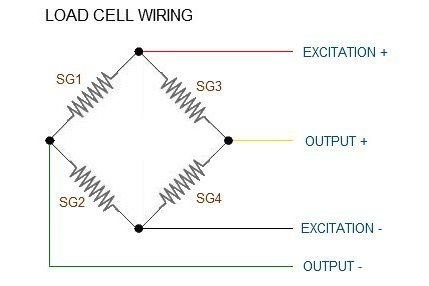
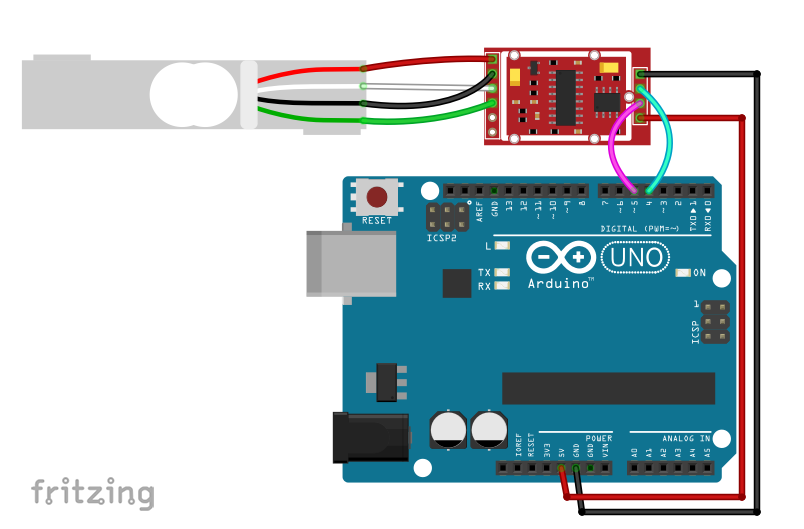
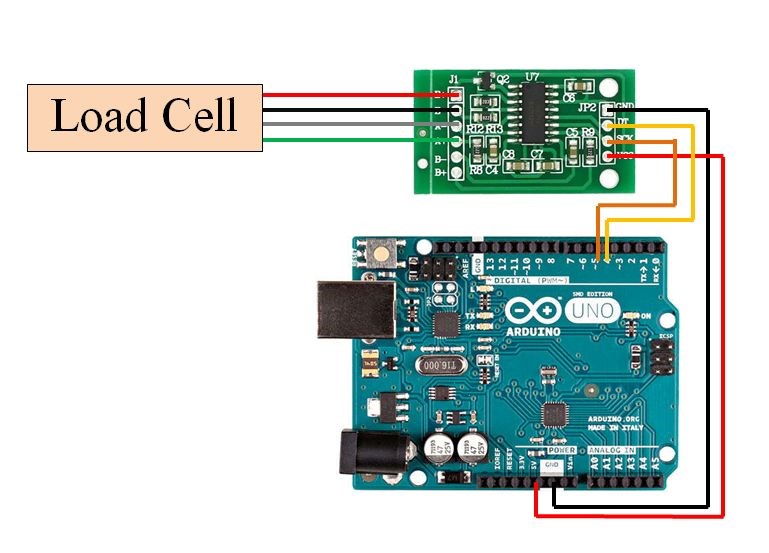
Load cells have 4 wires:
- Red for Excitation+
- Black for Excitation-
- White for Output-
- Green for Output+
Required Materials
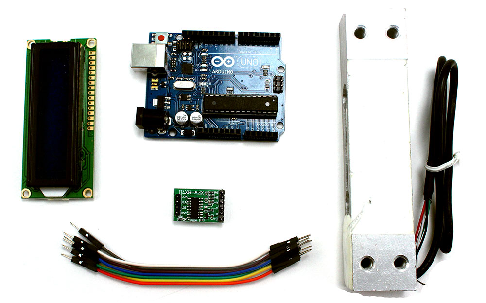
Hardware Components
Software Apps
Interfacing a Load Cell with Arduino
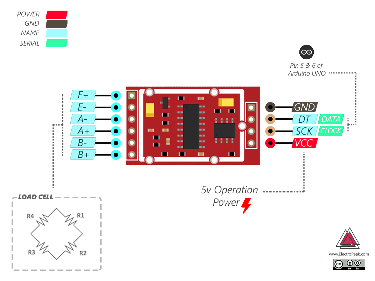
| Loaedcell | HX711 | HX711 | Arduino |
|---|---|---|---|
| Red | E+ | Vcc | 5v |
| Black | E- | GND | GND |
| White | A- | SCK | 5 |
| Greeen | A+ | DT | 6 |
Circuit
Note

Load Cell Calibration
To use a load cell, first you need to calibrate it. To do this upload the following code on your Arduino board. Wait until the Reading message is displayed on the serial monitor and then place a specified weight item on the load cell. Using the A key, you can increase the calibration_factor one unit and you can use the Z key to decrease it to get the correct weight. Now your scale is calibrated!
Code
You need HX711 Library:
/*
 *  HX711 Calibration
 *  by Hanie Kiani
 *  https://electropeak.com/learn/
 */
/*
 Setup your scale and start the sketch WITHOUT a weight on the scale
 Once readings are displayed place the weight on the scale
 Press +/- or a/z to adjust the calibration_factor until the output readings match the known weight
*/

#include "HX711.h"
#define DOUT  4
#define CLK  5
HX711 scale;

float calibration_factor = 2230; // this calibration factor must be adjusted according to your load cell
float units;
void setup() {
  scale.begin(DOUT, CLK);
  Serial.begin(9600);
  Serial.println("HX711 calibration sketch");
  Serial.println("Remove all weight from scale");
  Serial.println("After readings begin, place known weight on scale");
  Serial.println("Press + or a to increase calibration factor");
  Serial.println("Press - or z to decrease calibration factor");

  scale.set_scale(calibration_factor); //Adjust to this calibration factor
  scale.tare();  //Reset the scale to 0

  long zero_factor = scale.read_average(); //Get a baseline reading
  Serial.print("Zero factor: "); //This can be used to remove the need to tare the scale. Useful in permanent scale projects.
  Serial.println(zero_factor);
}

void loop(){

  Serial.print("Reading");
  units = scale.get_units(), 5;
  if (units < 0)
  {
    units = 0.00;
  }
  Serial.print("Weight: ");
  Serial.print(units);
  Serial.print(" grams");
  Serial.print(" calibration_factor: ");
  Serial.print(calibration_factor);
  Serial.println();

  if(Serial.available())
  {
    char temp = Serial.read();
    if(temp == '+' || temp == 'a')
      calibration_factor += 1;
    else if(temp == '-' || temp == 'z')
      calibration_factor -= 1;
  }
  if(Serial.available())
  {
    char temp = Serial.read();
    if(temp == 't' || temp == 'T')
      scale.tare();  //Reset the scale to zero
  }
}
set_scale(); function set the calibration_factor, which uses for the scale calibration, to desired value and tare(); function set it to zero.
get_units(); function reads the weight and if it is smaller than zero, it is considered to be zero. Measuring the Weight of Objects
Circuit
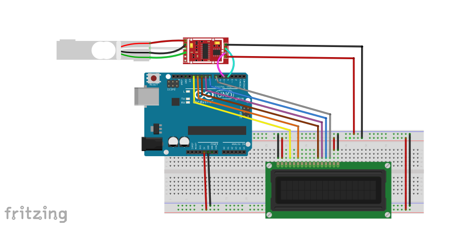
Code
/*
 *  Digital Weighing Scale with Load Cell
 *  by Hanie kiani
 *  https://electropeak.com/learn/
 */

#include "HX711.h"  //You must have this library in your arduino library folder
#include <LiquidCrystal.h>
LiquidCrystal lcd(12, 11, 10, 9, 8, 7);
#define DOUT  4
#define CLK  5

HX711 scale;

float calibration_factor = 2230; // this calibration factor is adjusted according to my load cell
float units;

void setup() {
  scale.begin(DOUT, CLK);
  lcd.begin(16,2);
  Serial.begin(9600);
  Serial.println("Press T to tare");

  scale.set_scale(calibration_factor); //Adjust to this calibration factor
  scale.tare();
}


void loop() {

 units = scale.get_units(), 5;
  if (units < 0)
  {
    units = 0.00;
  }
  lcd.setCursor(0,0);
  lcd.print("Weight: ");
  lcd.setCursor(8,0);
  lcd.print(units,5); //displays the weight in 4 decimal places only for calibration
  lcd.setCursor(14,0);
  lcd.print("grams");


  if(Serial.available())
  {
    char temp = Serial.read();
    if(temp == 't' || temp == 'T')
      scale.tare();  //Reset the scale to zero
  }
}
Make a Force Gauge
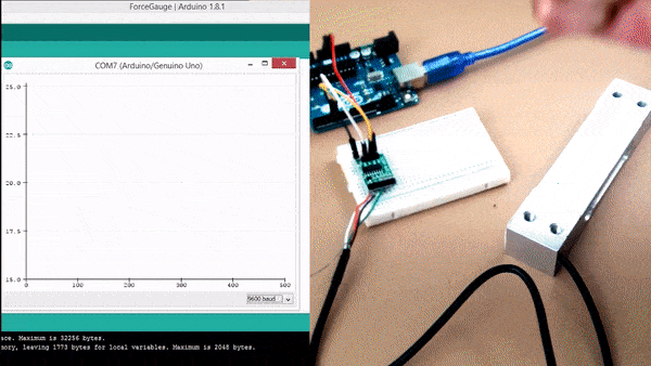
You can also use load cell module to measure the force in newtons.To do this, you can upload the following code after applying a proper calibration_factor on your board, and see the result by applying different forces to the load cell.
Note
Place the load cell on a flat surface. Then apply a force to it with your hand. You can see when you apply more force to load the cell, a larger number is displayed on the LCD.
Code
/*
*  Digital Force Gauge with Loa d Cell
*  by Hanie kiani
*  https://electropeak.com/learn/
*/

#include "HX711.h"  //You must have this library in your arduino library folder
#include <LiquidCrystal.h>
LiquidCrystal lcd(12, 11, 10, 9, 8, 7);
#define DOUT  4
#define CLK  5
HX711 scale;

float calibration_factor = 1; // this calibration factor is adjusted according to my load cell
float units;

void setup() {
  scale.begin(DOUT, CLK);
  lcd.begin(16,2);
  Serial.begin(9600);
  Serial.println("Press T to tare");
 scale.set_scale(calibration_factor); //Adjust to this calibration factor
  scale.tare();
}


void loop() {

 units = scale.get_units(), 5;
  if (units < 0)
  {
    units = 0.00;
  }
  lcd.setCursor(0,0);
  lcd.print("Force: ");
   Serial.print("Force: ");
  lcd.setCursor(8,0);
  lcd.print(units,5); //displays the weight in 4 decimal places only for calibration
   Serial.print(units,5);
  lcd.setCursor(14,0);
  lcd.print("N");
   Serial.print("N ");
     Serial.println();
delay(2000);


  if(Serial.available())
  {
    char temp = Serial.read();
    if(temp == 't' || temp == 'T')
      scale.tare();  //Reset the scale to zero
  }
}
Warning
What's Next?
- By adding a potentiometer and a rotary encoder to the circuit, make the user able to change the measurement unit.
- Add the possibility to define a custom “zero” condition. This is useful when there is already an object on the scale and you want to measure the weight of a new object.

Comments (16)
Wonderful tutorial. Thanks.
It would be amazing if you put some source codes for AVR.
Thank you again.
Thank you.
We always try to do our best.
When pasting this code into the IDE, it says the ” error: no matching function for call to ‘HX711::HX711(int, int)” What do I need to alter in the code? I have installed all of the libraries.
Does your libraries up to date?
Yes my libraries are up to date , still same error : no matching function for call HX711::HX711(int,int); . What need to be changed
Hello, I love this project. I want to create a permanent scale with the options listed in “What’s Next”. Do you have suggestions for parts and code that would fulfill this?
Hello Neil,
Thanks for your reply. To make this module function as a scale, I recommend using two sheets of acrylic along with this module, similar to how it’s done in this product. Additionally, you can use this product for a more compact design and to display the values directly on its screen.
same bro… did you resolve it in any way
Could you please elaborate on how this code would be changed to incorporate multiple load cells?
I am currently working on making a three load cell scale which will measure the force applied onto it in Newtons. Any coding examples you can provide would be greatly appreciated!
Hi,
I think you should use three HX711 seperatly
Arduino: 1.8.16 (Windows 10), Board: “Arduino Uno”
sketch_sep11a:15:22: error: no matching function for call to ‘HX711::HX711(int, int)’
HX711 scale(DOUT, CLK);
^
In file included from C:\Users\Thulasiraman R\Documents\Arduino\sketch_sep11a\sketch_sep11a.ino:12:0:
C:\Users\Thulasiraman R\Documents\Arduino\libraries\HX711-master\src/HX711.h:30:3: note: candidate: HX711::HX711()
HX711();
^~~~~
C:\Users\Thulasiraman R\Documents\Arduino\libraries\HX711-master\src/HX711.h:30:3: note: candidate expects 0 arguments, 2 provided
C:\Users\Thulasiraman R\Documents\Arduino\libraries\HX711-master\src/HX711.h:19:7: note: candidate: constexpr HX711::HX711(const HX711&)
class HX711
^~~~~
C:\Users\Thulasiraman R\Documents\Arduino\libraries\HX711-master\src/HX711.h:19:7: note: candidate expects 1 argument, 2 provided
sketch_sep11a:19:12: error: expected initializer before ‘}’ token
void setup }()
^
sketch_sep11a:19:12: error: expected declaration before ‘}’ token
exit status 1
no matching function for call to ‘HX711::HX711(int, int)’
This report would have more information with
“Show verbose output during compilation”
option enabled in File -> Preferences.
Hi, thank you for the feedback!
There was something wrong with the code. Now it’s updated.
Hi! I followed all the instructions above to construct my circuit and input the code into the Arduino board, but the LCD display shows nothing but a blue screen. I’m wondering if anyone has encountered the same issue? Thanks!
Hi,
To troubleshoot the problem, first, double check the wiring. Sometimes a disconnection of a single wire can result in the malfunction of the whole circuit. If the wiring was properly done, the problem might be related to the the voltage of the backlight pin of the LCD. Actually, there must be a resistor -around 1 to 10 KOhm- between the backlight pin of the LCD -pin 15- and 5V. The character LCD we have used in this tutorial has an onboard resistor connected to pin 15. But the LCD you have might not have it. So, you need to add one between 5V and pin 15. Hope that solves your problem! Good luck.
How to measure more significant figures. you say “you will create a digital scale that can measure the weight with an accuracy of 0.0001 grams and also a force gauge.” How do I modify the sketch or library to be able to include those additional significant figures?
PLEASE HELP IT IS COMING LIKE THIS!!
Sketch uses 5896 bytes (18%) of program storage space. Maximum is 32256 bytes.
Global variables use 301 bytes (14%) of dynamic memory, leaving 1747 bytes for local variables. Maximum is 2048 bytes.
avrdude: stk500_recv(): programmer is not responding
avrdude: stk500_getsync() attempt 1 of 10: not in sync: resp=0x8d
avrdude: stk500_recv(): programmer is not responding
avrdude: stk500_getsync() attempt 2 of 10: not in sync: resp=0x8d
avrdude: stk500_recv(): programmer is not responding
avrdude: stk500_getsync() attempt 3 of 10: not in sync: resp=0x8d
avrdude: stk500_recv(): programmer is not responding
avrdude: stk500_getsync() attempt 4 of 10: not in sync: resp=0x8d
avrdude: stk500_recv(): programmer is not responding
avrdude: stk500_getsync() attempt 5 of 10: not in sync: resp=0x8d
avrdude: stk500_recv(): programmer is not responding
avrdude: stk500_getsync() attempt 6 of 10: not in sync: resp=0x8d
avrdude: stk500_recv(): programmer is not responding
avrdude: stk500_getsync() attempt 7 of 10: not in sync: resp=0x8d
avrdude: stk500_recv(): programmer is not responding
avrdude: stk500_getsync() attempt 8 of 10: not in sync: resp=0x8d
avrdude: stk500_recv(): programmer is not responding
avrdude: stk500_getsync() attempt 9 of 10: not in sync: resp=0x8d
avrdude: stk500_recv(): programmer is not responding
avrdude: stk500_getsync() attempt 10 of 10: not in sync: resp=0x8d
Failed uploading: uploading error: exit status 1