
Product added to cart

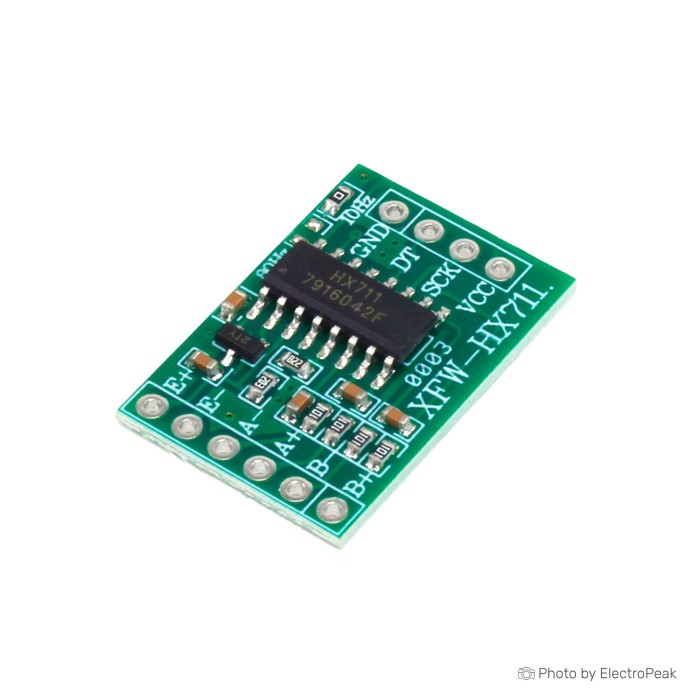
HX711 Dual-Channel 24-bit A/D Conversion Module
$0.4100
In stock
SKU
SEN-13-017
Volume discounts:
- +100 5 % $0.3900
- +500 7 % $0.3800
- +5000 10 % $0.3700
- +10000 12 % $0.3600
Ships in 2-3 business days, then:
Free delivery in 12-15 days by Tracked Economic Shipping on orders over $100.
Free delivery in 7-10 days by Express Shipping on orders over $300.
More shipping info

Shop with confidence Learn More
 ENC28J60 Network Controller for Relay Module Previous
HX711 Load Cell Module Review
The HX711 Dual-Channel 24-bit A/D Conversion Module is an analog-to-digital converter breakout that amplifies the millivolt-level differential signals produced by bridge sensors. Measuring 35 mm by 21 mm, it provides an accessible interface for weight scales, presence detectors, and slow force-measurement prototypes. Its onboard low-noise programmable gain amplifier and 24-bit converter turn the small mechanical deformations detected by a Wheatstone bridge into serial data that standard microcontroller GPIO pins can read.
A bridge sensor alone cannot effectively drive a microcontroller analog pin because full-scale strain-gauge bridge output is typically only a few millivolts. This board fills that gap. It supplies excitation voltage to power the bridge, amplifies the sensor's returned differential voltage, and sends digitized values through a two-wire serial interface. For hobbyist scales or automated inventory bins, pairing this breakout with a 5 kg load cell creates a straightforward measurement system. See the broader adapters and converters category for related interface options.
The main trade-off is its single-rail implementation and communication architecture. The module accepts an input voltage range from 2.7 V to 5 V, but exposes one VCC rail without isolated analog and digital power routing. Hosts operating strictly at 3.3 V require careful verification of the data output line to avoid exceeding input voltage tolerances. For builds that need separate filtering between analog and digital rails, the HX711 Load Cell Amplifier - Red uses an alternative layout with dedicated LC filtering on the analog supply path.
Specifications of HX711 Dual-Channel 24-bit A/D Conversion Module
- Chip: HX711
- Resolution: 24 bit
- Channel: 2 Channel
- Input Voltage: 2.7V ~ 5V
- Operation Current: <1.5mA
- Output Data Rate: 10SPS or 80SPS
- Supply Rejection: Simultaneous 50 and 60Hz
- Pin Number: 10 Pin
- Size: 35mm x 21mm
- E+: Excitation positive
- E-: Excitation negative
- A-: Channel A Negative Input
- A+: Channel A positive Input
- B-: Channel B Negative Input
- B+: Channel B positive Input
- GND: 0V / Ground Power Connection
- DT: Data IO Connection
- SCK: Serial Clock Input
- VCC: Power Input
HX711 Load Cell Module Specifications Explained
To interpret the HX711 specifications, separate raw converter capability from real-world system accuracy. A 24-bit analog-to-digital converter provides over 16 million discrete output counts, but mechanical settling, thermal drift, and electrical noise determine the usable resolution. The table below shows how each listed specification affects physical scale builds.
| Specification | Value | Why It Matters |
|---|---|---|
| Resolution | 24 bit | Provides high digital granularity for small bridge voltage changes. It does not guarantee 24-bit noise-free measurement; stable mass readings depend directly on bridge quality, mechanical rigidity, and electrical shielding. |
| Channel Count | 2 Channel | Offers two differential inputs (Channel A and Channel B) routed through an internal multiplexer to a single converter. Channels are sampled alternately rather than simultaneously. Channel A provides selectable 128x or 64x gain, while Channel B features a fixed 32x gain. |
| Input Voltage | 2.7V ~ 5V | Allows operation across common logic ranges. On this breakout, the single VCC connection dictates both the digital communication level and the excitation voltage supplied to the sensor. |
| Operation Current | <1.5mA | Reflects the typical quiescent draw of the converter IC under internal regulation. Total current consumption increases once the load cell resistance is powered via the excitation pins. |
| Output Data Rate | 10SPS or 80SPS | Determines conversion latency and update frequency. A 10 samples-per-second rate provides high 50 Hz and 60 Hz line-noise rejection for stable static scales, while 80 SPS suits dynamic presence detection at the expense of higher noise. This specific board does not expose a dedicated pin to toggle rates on the fly. |
| Supply Rejection | Simultaneous 50 and 60Hz | Suppresses mains hum when running at the default 10 SPS rate, minimizing 50 Hz and 60 Hz electrical interference from surrounding AC power wiring. |
| Physical Size | 35mm x 21mm | Defines mounting footprint inside scale bases or junction boxes. Projects with severe enclosure constraints can alternatively evaluate the HX711 Load Cell Amplifier - Purple, which utilizes a 22 mm by 22 mm square board format. |
HX711 Load Cell Module Wiring, Voltage and Compatibility
Connect a four-wire Wheatstone bridge load cell by electrical function, not wire insulation color. Wire colors vary among load cell manufacturers. Use the sensor datasheet or measure resistance across the pairs with a multimeter: the higher-resistance pair is the excitation path and connects to E+ and E-, while the lower-resistance pair is the signal output and connects to A+ and A-.
| System Interface | Implementation Details | Compatibility Notes |
|---|---|---|
| Sensor Interface (Channel A) | E+, E-, A+, A- | Primary connection for standard full-bridge load cells. Connects bridge excitation across E+/E- and the differential signal to A+/A- for 128x or 64x internal amplification. |
| Secondary Sensor (Channel B) | B+, B- | Auxiliary differential input with fixed 32x gain. Shares the excitation terminals (E+/E-) with Channel A. Cannot be read concurrently with Channel A. |
| Host Communication | DT (Data Output) and SCK (Clock Input) | Uses a proprietary, two-wire serial protocol clocked by the microcontroller. This is not standard SPI, I2C, or UART hardware; any two general-purpose digital input/output pins can manage the protocol. |
| Logic and Power Voltage | VCC (2.7 V to 5 V) and GND | When powered from 5 V, the DT line outputs 5 V logic. Connecting a 5 V-powered board directly to 3.3 V-only microcontrollers (such as ESP32 or STM32) risks damaging the host GPIO unless level shifting is implemented. |
| Host Platforms | Arduino AVR, ESP8266, ESP32, STM32 | Widely supported via standard open-source HX711 libraries across major development environments. Direct 3.3 V operation is supported by the IC, but excitation stability depends on supply rail consistency. |
For complete connection diagrams and sample sketches with classic 5 V boards, see the Arduino HX711 wiring guide or the broader Arduino digital weight-scale guide. Where hosts separate analog and digital power domains, the HX711 Load Cell Amplifier - Red provides dedicated decoupling on its analog supply lines.
Required and Recommended Hardware
This board is strictly an analog-to-digital converter breakout, so external hardware is required for a functioning weighing mechanism:
- Required Sensors: Match the bridge load cell to your mechanical load requirements: a 1 kg load cell for precision balances, a 5 kg load cell for kitchen scales, a 10 kg load cell for general benchtop tasks, or a 20 kg load cell for heavier platform bins.
- Required Host: Use a microcontroller or development board with at least two available digital GPIO pins and a common ground reference.
- Required Power Source: Provide a stable direct-current supply between 2.7 V and 5 V with minimal ripple.
- Required Calibration Standard: Use a known reference mass to calibrate raw digital counts into grams or kilograms.
- Recommended Equipment: A digital multimeter verifies bridge resistance and identifies signal pairs before power is applied.
- Recommended Wiring: Soldered connections or strain-relieved terminal blocks prevent erratic readings caused by loose contact resistance.
- Recommended Protection: Add logic-level shifting circuitry when connecting a 5 V-powered HX711 module to 3.3 V microcontrollers.
- Optional Additions: Add a secondary bridge sensor to Channel B for non-synchronized differential monitoring, or use protective mechanical base plates to limit physical over-travel on the load cell.
HX711 Load Cell Module Limitations and Calibration
The HX711 outputs raw signed 24-bit integers, not engineering units. An uncalibrated system returns numbers roughly between -8,388,608 and 8,388,607 that shift with temperature, wiring resistance, and mechanical pre-load. Real-world weight measurement requires a two-step firmware calibration routine: establish a zero-load reference (tare), then calculate a calibration factor with a verified reference weight.
Channel architecture is another common source of confusion. Although labeled as a two-channel module, the chip has only one analog-to-digital converter. An internal multiplexer switches between Channel A and Channel B. When reading both channels, firmware must command the switch and discard initial settling conversions, which prevents synchronized dual-axis force captures. Channel A provides programmable gain settings of 128x (giving a full-scale differential input of ±20 mV at 5 V excitation) or 64x (±40 mV), whereas Channel B is fixed at 32x gain (±80 mV).
Reading stability depends heavily on electrical and environmental hygiene. High-gain amplification makes the analog input sensitive to electromagnetic interference, loose jumper wires, and unstable power supplies. For step-by-step firmware implementations and tare calculations, refer to the Arduino digital weight-scale guide.
HX711 Load Cell Module Alternatives
Board dimensions, supply isolation, and display integration determine which load cell interface form factor fits an assembly. These options address specific wiring and layout constraints:
- HX711 Load Cell Amplifier - Red: This equivalent HX711 breakout separates analog and digital supply rails and includes an integrated 3.3 µH inductor and 0.1 µF filter capacitor. It suits environments with high electrical noise on the primary power bus.
- HX711 Load Cell Amplifier - Purple: This equivalent breakout uses an ultra-compact 22 mm by 22 mm square footprint. It is intended for miniature assemblies, compact wearable devices, or space-constrained scale enclosures where the standard 35 mm board length cannot fit.
- HX711 4-Digit Display Module: This standalone weighing platform combines the HX711 converter with an integrated 4-digit numeric LED display, onboard buttons, and persistent memory. It supports direct readout up to 9999 g without an external microcontroller or custom firmware.
HX711 Load Cell Module Setup Check
Before permanently mounting the hardware, use this benchtop verification sequence to confirm that the load cell and breakout module are functioning properly:
- Connect the load cell bridge wires to the analog terminal side: excitation positive to E+, excitation negative to E-, signal positive to A+, and signal negative to A-. A medium-capacity unit such as a 10 kg load cell works well for initial bench testing.
- Connect GND to microcontroller ground, VCC to an appropriate power pin, DT to a digital input pin, and SCK to a digital output pin.
- Confirm that logic voltage thresholds match the microcontroller. When running the module at 5 V with a 3.3 V host, add inline logic shifting on the DT line.
- Install an established open-source HX711 library in the development environment, then load a basic raw-value reading sketch configured with the selected pin numbers. For detailed library configuration, consult the Arduino HX711 wiring guide.
- Open the serial monitor and confirm that the module reports changing raw integer counts when manual finger pressure is applied to the load cell cantilever.
- Remove all physical force from the sensor, execute the tare command to zero the baseline offset, apply a known reference mass, and record the calibration factor that converts counts into units of mass.
HX711 Load Cell Module FAQ
Does the HX711 Dual-Channel 24-bit A/D Conversion Module include a load cell?
No. This module includes only the amplifier breakout board. You must provide a compatible Wheatstone bridge sensor, such as a 1 kg load cell or higher-capacity variant, along with connecting wires and mounting hardware.
Can this module read two load cells at the same time?
No, it cannot sample two load cells simultaneously. The module has two differential input channels (A and B) that share a single internal analog-to-digital converter through an input multiplexer, so the channels must be read sequentially.
Which channel should I use for a standard load cell?
Use Channel A (pins A+ and A-) for standard weighing projects. It provides software-selectable 128x or 64x amplification for typical millivolt bridge outputs, while Channel B is limited to a fixed 32x gain.
Can I use this HX711 module with an ESP32 or ESP8266?
Yes, HX711 software libraries support ESP32 and ESP8266 microcontrollers. Because these processors use 3.3 V logic and are not 5 V tolerant, you must either power the module rail at 3.3 V or use a logic-level converter on the DT line when powering the board from 5 V.
Can this module run reliably from a 3.3 V power supply?
The HX711 integrated circuit is specified to operate down to 2.7 V, allowing 3.3 V operation. At 3.3 V, the excitation voltage supplied to the load cell drops proportionally, lowering the bridge's millivolt output and reducing signal-to-noise ratio compared with a 5 V excitation supply.
Is it safe to connect a 5 V-powered HX711 module directly to 3.3 V microcontroller pins?
No, not without level shifting. When the module is powered by 5 V, its DT pin outputs 5 V high-level logic signals, which can degrade or permanently damage GPIO pins on 3.3 V processors such as the ESP32.
Why does the HX711 output raw numbers instead of grams?
The onboard converter reports raw digital conversion counts proportional to the analog voltage differential across its inputs. To convert these arbitrary values into grams or kilograms, your microcontroller code must subtract the zero-load offset (tare) and divide by a scaling factor determined with a known weight.
Does 24-bit resolution guarantee high-precision weight readings?
No. A 24-bit resolution describes the converter's mathematical code width, not practical measurement accuracy. Real-world weighing stability is limited by mechanical deflection, platform stiffness, temperature fluctuations, thermal EMF, and electrical noise.
Can I switch the data output rate between 10 SPS and 80 SPS on this board?
The HX711 chip supports both 10 SPS and 80 SPS rates, but this breakout does not expose the RATE pin to a header or provide an onboard selector switch. Changing the sampling rate typically requires lifting pin 15 of the IC or bridging onboard surface-mount pads, depending on the underlying PCB trace routing.
Is there a way to display weight without writing code for a microcontroller?
Yes. The HX711 4-Digit Display Module is a standalone board that integrates an HX711 amplifier, a 4-digit seven-segment display, and pushbutton calibration routines to measure and display loads up to 9999 g without writing firmware.
Purchase Decision Summary
| Project Fit | Recommendation |
|---|---|
| Ideal For |
|
| Consider With Adjustments |
|
| Consider Another Option |
|
Buying Checklist
- Confirm that your sensor is a compatible Wheatstone bridge load cell rather than an unamplified piezoelectric disc or resistive force film.
- Select a load cell capacity (1 kg, 5 kg, 10 kg, or 20 kg) that matches the anticipated mechanical load range without exceeding physical yield limits.
- Ensure that the load cell includes documented wire functions for excitation (+/-) and differential signal (+/-).
- Verify that the host microcontroller has two free general-purpose digital I/O pins for the serial DT and SCK interface.
- Plan logic voltage compatibility: prepare level-shifting hardware when connecting a 5 V-powered module to a 3.3 V-only processor.
- Ensure access to a known reference weight to calculate the software calibration multiplier.
- Prepare mechanical baseplates, standoffs, and rigid mounting surfaces to prevent cantilever binding or torsional frame distortion.
- Confirm that the sequential multiplexing behavior of Channels A and B matches the measurement timing requirements.
| Interface Type | Digital |
|---|---|
| Operating Voltage (V) | 2.7 - 5 |
| Operating Current (mA) | < 1.5 mA |
| Operating Temp (°C) | -40 to 85 |
| Dimensions (mm) | 24x16mm |
| Mounting Type | THT |
| Encoder Resolution (PPR) | 24-bit |
| Output Type | Digital |
| Channels | 2-channel |
| Chipset | HX711 |
| Voltage Range | 2.7V ~ 5V |
| Conversion Type | Analog to Digital |
| Pins | 10 pins |
Write Your Own Review

Please complete your information below to login.
Sign In
Create New Account