
Overview
In this tutorial, you’ll learn about the TCS230 sensor and how to use it with Arduino to recognize colors.
At the end of this tutorial, you’ll find a fascinating idea to create a color picker pen. With this pen, you can scan the colors of the objects around you, and start painting on an LCD using that color.
What You Will Learn
- An introduction of TCS230
- How to use the TCS230 module with Arduino and recognize different colors
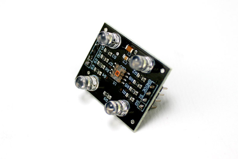
What Is the TSC230 Sensor?
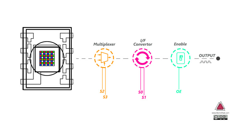
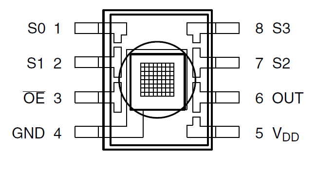
TCS230 Pinout

| S0 | S1 | OUTPUT FREQUENCY SCALING (f0) | S2 | S3 | PHOTODIODE TYPE | |
|---|---|---|---|---|---|---|
| L | L | Power down | L | L | Red | |
| L | H | 2% | L | H | Blue | |
| H | L | 20% | H | L | Clear (no filter) | |
| H | H | 100% | H | H | green |
Required Materials

Hardware Components
Software Apps
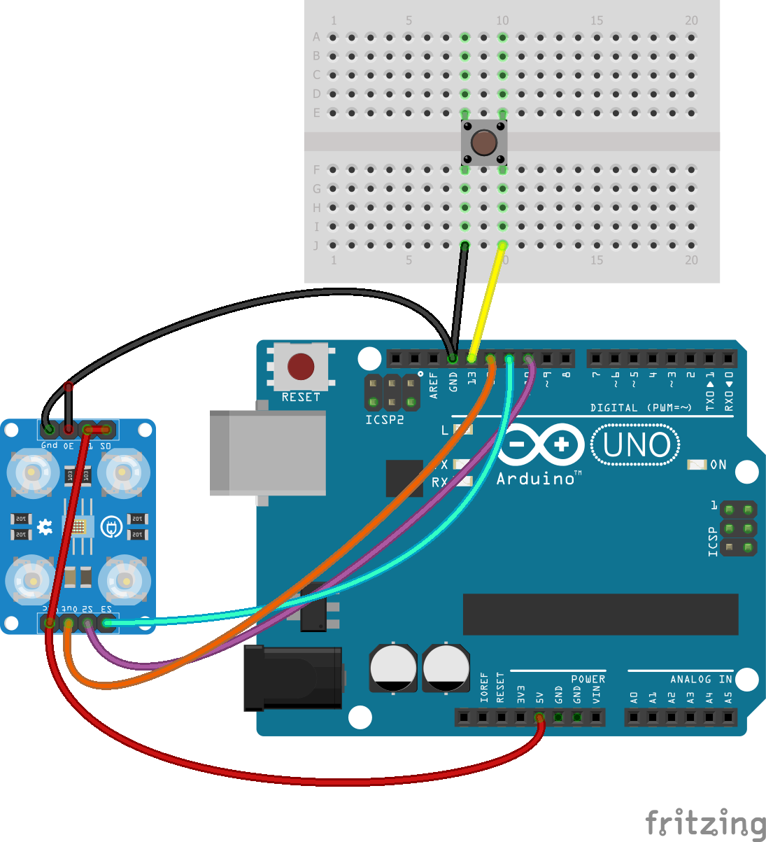
TCS239 Color Sensor and Arduino interfacing
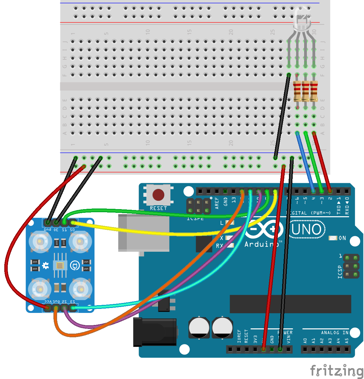
Circuit
Code
The following code measures the output signal for each of the three colors and displays the result on the serial port.
/*
  TCS230 color recognition sensor
  modified on 7 May 2019
  by Mohammadreza Akbari @ Electropeak
  Home

Color Sensor      Arduino
-----------      --------
 VCC               5V
 GND               GND
 s0                8
 s1                9
 s2                10
 s3                11
 OUT               12
 OE                GND
*/
const int s0 = 8;
const int s1 = 9;
const int s2 = 10;
const int s3 = 11;
const int out = 12;
// LED pins connected to Arduino
int redLed = 2;
int greenLed = 3;
int blueLed = 4;
// Variables
int red = 0;
int green = 0;
int blue = 0;

void color()
{
  digitalWrite(s2, LOW);
  digitalWrite(s3, LOW);
  //count OUT, pRed, RED
  red = pulseIn(out, digitalRead(out) == HIGH ? LOW : HIGH);
  digitalWrite(s3, HIGH);
  //count OUT, pBLUE, BLUE
  blue = pulseIn(out, digitalRead(out) == HIGH ? LOW : HIGH);
  digitalWrite(s2, HIGH);
  //count OUT, pGreen, GREEN
  green = pulseIn(out, digitalRead(out) == HIGH ? LOW : HIGH);
}

void setup()
{
  Serial.begin(9600);
  pinMode(s0, OUTPUT);
  pinMode(s1, OUTPUT);
  pinMode(s2, OUTPUT);
  pinMode(s3, OUTPUT);
  pinMode(out, INPUT);
  pinMode(redLed, OUTPUT);
  pinMode(greenLed, OUTPUT);
  pinMode(blueLed, OUTPUT);
  digitalWrite(s0, HIGH);
  digitalWrite(s1, HIGH);
}

void loop()
{
  color();
  Serial.print("R Intensity:");
  Serial.print(red, DEC);
  Serial.print(" G Intensity: ");
  Serial.print(green, DEC);
  Serial.print(" B Intensity : ");
  Serial.print(blue, DEC);
  //Serial.println();

  if (red < blue && red < green && red < 20)
  {
   Serial.println(" - (Red Color)");
   digitalWrite(redLed, HIGH); // Turn RED LED ON
   digitalWrite(greenLed, LOW);
   digitalWrite(blueLed, LOW);
  }

  else if (blue < red && blue < green)
  {
   Serial.println(" - (Blue Color)");
   digitalWrite(redLed, LOW);
   digitalWrite(greenLed, LOW);
   digitalWrite(blueLed, HIGH); // Turn BLUE LED ON
  }

  else if (green < red && green < blue)
  {
   Serial.println(" - (Green Color)");
   digitalWrite(redLed, LOW);
   digitalWrite(greenLed, HIGH); // Turn GREEN LED ON
   digitalWrite(blueLed, LOW);
  }
  else{
  Serial.println();
  }
  delay(300);
  digitalWrite(redLed, LOW);
  digitalWrite(greenLed, LOW);
  digitalWrite(blueLed, LOW);
 }
The color function controls the S2 and S3 pins to read all the colors of the object. This function uses the pulseln command to receive the transmitted pulses by the color sensor.
For more information, you can read this page.

conditional operator?
TCS230 Color Sensor Calibration
Code
/*
  // TCS230 color recognition with calibration
  modified on 7 May 2019
  by Mohammadreza Akbari @ Electropeak
  Home

  Color Sensor      Arduino
  -----------      --------
  VCC               5V
  GND               GND
  s0                8
  s1                9
  s2                10
  s3                11
  OUT               12
  OE                GND
*/
const int s0 = 8;
const int s1 = 9;
const int s2 = 10;
const int s3 = 11;
const int out = 12;
// LED pins connected to Arduino
int redLed = 5;
int greenLed = 6;
int blueLed = 3;
// Variables
int red = 0;
int green = 0;
int blue = 0;

// Calibrated value
int cal_min = 5;
int cal_max_r = 50;
int cal_max_g = 50;
int cal_max_b = 50;

void calibrate() {
  Serial.println("Clear sensor area. Then enter c again");
    while (Serial.read() != 'c') {
      //do nothing
      ;
    }
    color();
    cal_max_r = red;
    cal_max_g = green;
    cal_max_b = blue;
    Serial.println("Put white color infront of sensor, Then enter c again");
    while (Serial.read() != 'c') {
      //do nothing
      ;
    }
    color();
    cal_min = (red + green + blue) / 3;
    Serial.println("calibrated successfully.");
    delay(300);
}

void color() {
  digitalWrite(s2, LOW);
  digitalWrite(s3, LOW);
  //count OUT, pRed, RED
  red = pulseIn(out, digitalRead(out) == HIGH ? LOW : HIGH);
  digitalWrite(s3, HIGH);
  //count OUT, pBLUE, BLUE
  blue = pulseIn(out, digitalRead(out) == HIGH ? LOW : HIGH);
  digitalWrite(s2, HIGH);
  //count OUT, pGreen, GREEN
  green = pulseIn(out, digitalRead(out) == HIGH ? LOW : HIGH);
}

void setup()
{
  Serial.begin(9600);
  pinMode(s0, OUTPUT);
  pinMode(s1, OUTPUT);
  pinMode(s2, OUTPUT);
  pinMode(s3, OUTPUT);
  pinMode(out, INPUT);
  pinMode(redLed, OUTPUT);
  pinMode(greenLed, OUTPUT);
  pinMode(blueLed, OUTPUT);
  digitalWrite(s0, HIGH);
  digitalWrite(s1, HIGH);
}

void loop()
{
  color();
  if (Serial.read() == 'c') {
    calibrate();
  }


  red = map(red, cal_min, cal_max_r, 255, 0);
  green = map(green, cal_min, cal_max_g, 255, 0);
  blue = map(blue, cal_min, cal_max_b, 255, 0);
  Serial.print("R Intensity:");
  Serial.print(red);
  Serial.print(" G Intensity: ");
  Serial.print(green);
  Serial.print(" B Intensity : ");
  Serial.println(blue);
  delay(200);
}
Make a Color Picker Pen with TCS230 Sensor and Arduino
Circuit
Code
/*
  TCS230 color picker + paint
  Modified on 8 May 2019
  By Mohammadreza Akbari @ Electropeak
  Home

  Color Sensor      Arduino
  -----------      --------
  VCC               5V
  GND               GND
  s0                5V
  s1                5V
  s2                10
  s3                11
  OUT               12
  OE                GND
*/

#include <Adafruit_GFX.h>    // Core graphics library
#include <Adafruit_TFTLCD.h> // Hardware-specific library
#include <TouchScreen.h>

#if defined(__SAM3X8E__)
#undef __FlashStringHelper::F(string_literal)
#define F(string_literal) string_literal
#endif

//LCD
#define YP A3  // must be an analog pin, use "An" notation!
#define XM A2  // must be an analog pin, use "An" notation!
#define YM 9   // can be a digital pin
#define XP 8   // can be a digital pin

#define TS_MINX 150
#define TS_MINY 120
#define TS_MAXX 920
#define TS_MAXY 940

// For better pressure precision, we need to know the resistance
// between X+ and X- Use any multimeter to read it
// For the one we're using, its 300 ohms across the X plate
TouchScreen ts = TouchScreen(XP, YP, XM, YM, 300);

#define LCD_CS A3
#define LCD_CD A2
#define LCD_WR A1
#define LCD_RD A0
// optional
#define LCD_RESET A4

// Assign human-readable names to some common 16-bit color values:
#define BLACK   0x0000
#define BLUE    0x001F
#define RED     0xF800
#define GREEN   0x07E0
#define CYAN    0x07FF
#define MAGENTA 0xF81F
#define YELLOW  0xFFE0
#define WHITE   0xFFFF

Adafruit_TFTLCD tft(LCD_CS, LCD_CD, LCD_WR, LCD_RD, LCD_RESET);

#define BOXSIZE 40
#define PENRADIUS 3
int oldcolor, ccolor;

#define MINPRESSURE 10
#define MAXPRESSURE 1000

//Color sensor
const int s2 = 10;
const int s3 = 11;
const int out = 12;

const int button = 13;


// Color variables
int red = 0;
int green = 0;
int blue = 0;

// Calibrated value
int cal_min = 5;
int cal_max_r = 50;
int cal_max_g = 50;
int cal_max_b = 50;

uint16_t my_color;

void calibrate() {
  Serial.println("Clear sensor area. Then enter c again");
  while (Serial.read() != 'c') {
    //do nothing
    ;
  }
  color();
  cal_max_r = red;
  cal_max_g = green;
  cal_max_b = blue;
  Serial.println("Put white color infront of sensor, Then enter c again");
  while (Serial.read() != 'c') {
    //do nothing
    ;
  }
  color();
  cal_min = (red + green + blue) / 3;
  Serial.println("calibrated successfully.");
  delay(300);
}

void color() {
  digitalWrite(s2, LOW);
  digitalWrite(s3, LOW);
  //count OUT, pRed, RED
  red = pulseIn(out, digitalRead(out) == HIGH ? LOW : HIGH);
  digitalWrite(s3, HIGH);
  //count OUT, pBLUE, BLUE
  blue = pulseIn(out, digitalRead(out) == HIGH ? LOW : HIGH);
  digitalWrite(s2, HIGH);
  //count OUT, pGreen, GREEN
  green = pulseIn(out, digitalRead(out) == HIGH ? LOW : HIGH);
}

void pick_color() {
  color();
  red = map(red, cal_min, cal_max_r, 255, 0);
  green = map(green, cal_min, cal_max_g, 255, 0);
  blue = map(blue, cal_min, cal_max_b, 255, 0);

  Serial.print("R Intensity:");
  Serial.print(red);
  Serial.print(" G Intensity: ");
  Serial.print(green);
  Serial.print(" B Intensity : ");
  Serial.println(blue);

  //my_color = tft.color565(abs(255 - red), abs(255 - green), abs(255 - blue));
  my_color = tft.color565(red, green, blue);
  tft.fillRect(0, 0, 6*BOXSIZE, BOXSIZE, my_color);


  delay(100);

}

void setup()
{
  Serial.begin(9600);
  tft.reset();
  delay(1000);
  uint16_t identifier = tft.readID();

  if (identifier == 0x9325) {
    Serial.println(F("Found ILI9325 LCD driver"));
  } else if (identifier == 0x9328) {
    Serial.println(F("Found ILI9328 LCD driver"));
  } else if (identifier == 0x7575) {
    Serial.println(F("Found HX8347G LCD driver"));
  } else if (identifier == 0x9341) {
    Serial.println(F("Found ILI9341 LCD driver"));
  } else if (identifier == 0x8357) {
    Serial.println(F("Found HX8357D LCD driver"));
  } else {
    Serial.print(F("Unknown LCD driver chip: "));
    Serial.println(identifier, HEX);
    Serial.println(F("If using the Adafruit 2.8\" TFT Arduino shield, the line:"));
    Serial.println(F("#define USE_ADAFRUIT_SHIELD_PINOUT"));
    Serial.println(F("should appear in the library header (Adafruit_TFT.h)."));
    Serial.println(F("If using the breakout board, it should NOT be #defined!"));
    Serial.println(F("Also if using the breakout, double-check that all wiring"));
    Serial.println(F("matches the tutorial."));
    return;
  }

  tft.begin(identifier);

  tft.fillScreen(BLACK);

  tft.fillRect(0, 0, 6*BOXSIZE, BOXSIZE, RED);
  my_color = RED;

  pinMode(s2, OUTPUT);
  pinMode(s3, OUTPUT);
  pinMode(out, INPUT);
  pinMode(button, INPUT_PULLUP);
}

void loop()
{
  if (Serial.read() == 'c') {
    calibrate();
  }

  while (digitalRead(button) == LOW) {
    pick_color();
  }

  TSPoint p = ts.getPoint();

  // if sharing pins, you'll need to fix the directions of the touchscreen pins
  //pinMode(XP, OUTPUT);
  pinMode(XM, OUTPUT);
  pinMode(YP, OUTPUT);
  //pinMode(YM, OUTPUT);

  // we have some minimum pressure we consider 'valid'
  // pressure of 0 means no pressing!

  if (p.z > MINPRESSURE && p.z < MAXPRESSURE) {
    /*
    Serial.print("X = "); Serial.print(p.x);
    Serial.print("\tY = "); Serial.print(p.y);
    Serial.print("\tPressure = "); Serial.println(p.z);
    */

    if (p.y < (TS_MINY-5)) {
      Serial.println("erase");
      // press the bottom of the screen to erase
      tft.fillRect(0, BOXSIZE, tft.width(), tft.height()-BOXSIZE, BLACK);
    }
    // scale from 0->1023 to tft.width
    p.x = map(p.x, TS_MINX, TS_MAXX, tft.width(), 0);
    p.y = map(p.y, TS_MINY, TS_MAXY, tft.height(), 0);
    /*
    Serial.print("("); Serial.print(p.x);
    Serial.print(", "); Serial.print(p.y);
    Serial.println(")");
    */

    if (((p.y-PENRADIUS) > BOXSIZE) && ((p.y+PENRADIUS) < tft.height())) {
      tft.fillCircle(p.x, p.y, PENRADIUS, my_color);
    }
  }
}
The pick_color function is called when the key is pressed. It reads the color of the object located near the sensor and changes the pen color to that color.
What’s Next?
- Make a small color sorter to sort lego pieces based on their color.

Comments (3)
please may i know from where did you get the color picker pen for this prototype
Hi,
It comes with the TFT LCD Display Shield.
there is some mistake in map method:
is: red = map(red, cal_min, cal_max_r, 255, 0);
should be : red = map(red, cal_min, cal_max_r, 0, 255);
the same with rest of the colors.