
Product added to cart

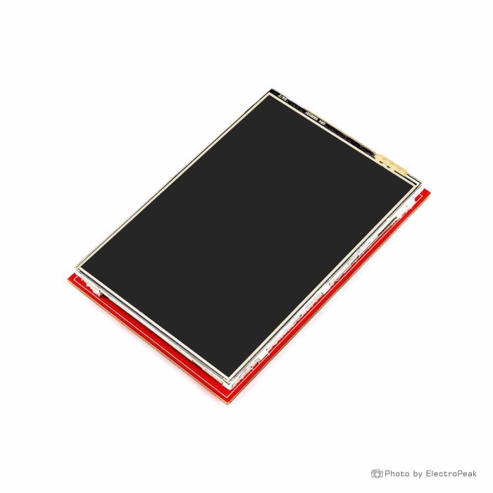
3.5 inch Full Color Touch TFT Display Module
$9.5000
In stock
SKU
LCD-01-135
Volume discounts:
- +25 4 % $9.1200
- +50 6 % $8.9300
- +100 8 % $8.7400
- +300 10 % $8.5500
- +500 12 % $8.3600
Ships in 2-3 business days, then:
Free delivery in 12-15 days by Tracked Economic Shipping on orders over $100.
Free delivery in 7-10 days by Express Shipping on orders over $300.
More shipping info

Shop with confidence Learn More
 1.8inch IPS Full Color TFT Display Module Previous
3.5 Inch Full Color Touch TFT Display Module Review
This 3.5 inch full color touch TFT display module combines a 480x320 pixel screen, pressure-based resistive touch, and an always-on white backlight on a narrow PCB board. It is intended for Arduino Mega-header display setups where the host microcontroller can spare at least twelve IO lines for graphical output and touch interaction. It suits control panels and graphical interfaces that can accommodate a multi-pin display connection. If your project needs low pin consumption, a confirmed controller model out of the box, or smartphone-style capacitive touch, evaluate this module carefully before ordering because the listing includes conflicting controller references.
When comparing TFT LCD modules, verified electrical and interface specifications help prevent wiring rework. Below are the complete specifications recorded for this display module:
Specifications of 3.5 inch Full Color Touch TFT Display Module
- Display size: 3.5 inch
- Resolution: 480x320 pixels
- Display type: TFT
- Display color: Full color
- Interface: SPI Parallel
- Minimum IO requirement: twelve IO
- Internal regulator: 5 or 3.3 volt
- Backlight: White
- Touch: Touch
- Driver: ILI9486 (RM68140)
- Driver test library: LCDWIKI_KBV
- Driver test setting: ILI9486
- Touch type: Resistive touch
- Operating voltage: DC 5V
- Driver: ILI9481
- Data bits: 8-16
- Distance: 1 mm
3.5 Inch Touch TFT Module Specifications Explained
These specifications translate directly into practical hardware decisions. The 480x320 resolution on a 3.5 inch viewing diagonal provides adequate pixel density for readable system menus, sensor plots, status readouts, and tactile UI buttons. As a resistive touch TFT display, it registers input through mechanical pressure from a fingernail or stylus rather than the electrical capacitance of a bare finger. It works with gloves. It does not support multi-touch gestures and requires software calibration during initial setup to align touch inputs with screen coordinates.
Plan the interface before choosing a host board. The module lists an ambiguous "SPI Parallel" interface, 8-16 data bits, and a minimum requirement of twelve IO lines. Assigning twelve or more pins to the display leaves limited GPIO on smaller microcontrollers. If your build cannot spare that many pins, the 2.8" SPI Touch TFT Module (ILI9341/ST7789) for pin-conscious projects uses a 4-wire SPI connection and includes a dimmable PWM backlight.
| Specification | Listed Value | Why It Matters to Your Build |
|---|---|---|
| Screen Size & Resolution | 3.5 inch, 480x320 pixels | Provides sufficient screen area for dashboards and text menus without requiring high-end graphics processing. |
| Touch Type | Resistive touch | Requires firm, point-based pressure; ideal for stylus input or gloved hands, but requires touch coordinate calibration. |
| IO Lines Required | Minimum twelve IO | Demands significant pin allocation; best suited to microcontrollers with large pin counts such as the Arduino Mega. |
| Backlight Control | White, always on | The backlight cannot be dimmed or switched off via standard software commands, drawing continuous power. |
| Operating Voltage | DC 5V (internal regulator: 5 or 3.3 volt) | Designed to run from a standard 5V rail; the internal regulator manages step-down, but universal 3.3V logic safety is unconfirmed. |
The white backlight is listed as always on, so sleep states and dimming options are unavailable in software without custom hardware modifications. For system power, the module lists a DC 5V operating voltage alongside an internal regulator for 5 or 3.3 volt. The onboard regulation handles step-down power needs, but verify exact pin signaling tolerances before wiring the module directly to native 3.3V boards. For other display form factors and technologies, browse the wider selection of LCDs.
3.5 Inch Touch TFT Module Compatibility and Setup
The module is described as suitable for Arduino Mega headers, making large ATmega-based boards its intended platform. The display itself does not require a USB driver; your computer communicates only with the host development board's serial interface. An Arduino Uno R3 host board for display testing can be used only after you verify connector fit and confirm that the minimum twelve IO requirements do not conflict with required peripherals.
For a verified plug-in form factor with documented pin usage, the 2.4 inch Arduino touch shield with stated MicroSD support offers a direct-mount option with an integrated card slot. If you are integrating this 3.5 inch display, use this basic bench test procedure:
- Inspect the physical header orientation and connector on the actual board before applying power.
- Supply the listed DC 5V power and map the minimum twelve IO control lines according to your physical board markings.
- Install the specified LCDWIKI_KBV driver test library into your Arduino IDE.
- Select the ILI9486 driver test setting in your library initialization code.
- Flash a basic color-fill or graphic test to confirm that the always-on white backlight illuminates and shapes render cleanly.
- Run a touch calibration sketch to determine the accurate minimum and maximum analog coordinate boundaries for the resistive panel.
For additional connection notes and example code, consult the full Arduino setup guide.
ILI9486 vs ILI9481: 3.5 Inch Touch TFT Driver and Touch Limits
Driver ambiguity is the main technical concern with this display. The specifications list both "Driver: ILI9486 (RM68140)" and "Driver: ILI9481." These are distinct LCD controller chips that require different register initialization commands. They are not interchangeable in code. If you flash firmware configured for an ILI9486 and see a blank white screen, the display glass may instead be connected to an ILI9481 controller.
Begin testing with the recommended LCDWIKI_KBV library configured for the ILI9486 setting. If initialization fails, switch the configuration profile to ILI9481 before changing your wiring. Generic display modules in this class can show controller variation between production batches, so confirming the driver is a necessary early troubleshooting step. The full Arduino setup guide includes more detail on library initialization.
Plan for these physical and electrical limitations:
- Resistive interaction: Resistive touch panels register touches through pressure. They lack multi-touch support and require user calibration to match screen pixel boundaries.
- Unswitched backlight: The white backlight is always on, so power-saving standby modes cannot darken the panel.
- Missing documentation: Exact PCB outer dimensions, mounting hole placements, touch controller IC part numbers, and operating current draw are not stated.
- Storage: No onboard MicroSD card slot is confirmed in the listing specifications.
Need a 3.5 inch panel on an Arduino header without touch input? The 3.5 inch non-touch Arduino display shield removes touch-calibration overhead while retaining the same viewing area.
3.5 Inch Touch TFT Module Alternatives
Display choice comes down to pin limits, processing overhead, and whether your user interface needs touch capability.
| Display Model | Screen Size & Resolution | Interface | Touch Type | Key Trade-Off |
|---|---|---|---|---|
| 3.5" Touch TFT (This Module) | 3.5", 480x320 | SPI Parallel (12 IO min) | Resistive | Conflicting controller listings; always-on backlight. |
| 2.4" Arduino Touch LCD Shield | 2.4", 240x320 | 8-bit Parallel | Resistive | Smaller screen area; consumes analog pins 0–3 and digital pins 5–13. |
| 2.8" SPI Touch TFT Module | 2.8", 320x240 | 4-wire SPI | Resistive | Lower resolution; requires logic conversion on 5V boards lacking regulators. |
| 3.5" Arduino LCD Shield (ILI9486) | 3.5", 480x320 | SPI | None (Non-touch) | No touch interaction; always-on backlight. |
| Nextion 7" NX8048T070 HMI | 7.0", 800x480 | TTL Serial (UART) | Resistive | Requires high power (5V, 2A) and proprietary Nextion Editor software. |
For a restricted board footprint, the 2.4 inch Arduino touch shield with stated MicroSD support provides a direct-plug solution with documented pin allocations. Pin-constrained setups are better matched to the 2.8" SPI Touch TFT Module (ILI9341/ST7789) for pin-conscious projects, which reduces host pin use to a standard 4-wire SPI bus and provides PWM backlight dimming. If touch input is unnecessary, the 3.5 inch non-touch Arduino display shield retains the same 480x320 viewing area and adds an onboard SD slot; setup guidance for that hardware is available in the non-touch 3.5 inch TFT shield setup article.
For complex graphical interfaces that overwhelm an 8-bit microcontroller, consider the Nextion 7" NX8048T070 standalone smart HMI display for offloaded UI processing. Its onboard processor and 16 MB flash memory render UI assets locally, while data exchanges with your controller over a simple serial UART connection. The trade-off is a 5V 2A power requirement.
3.5 Inch Touch TFT Module Accessories and Arduino Projects
Before assembling a setup around this module, verify what hardware is already on your bench. The module does not include a host microcontroller, connecting wires, a programming cable, or a stylus.
- Required Host Microcontroller: Use an Arduino board or compatible platform capable of driving at least twelve IO lines. An Arduino Uno R3 host board for display testing can handle initial verification once pin and connector fit are confirmed. You also need a matching USB cable to upload firmware from your computer.
- Recommended Wiring: If the module does not plug directly into compatible headers, use jumper wiring for a TFT module to break out individual signal paths.
- Recommended Prototyping Space: A breadboard setup for wired display modules is useful when you need to wire pull-up resistors or intermediate sensors alongside the display lines.
- Touch Stylus: A plastic resistive stylus improves precision when navigating small menus compared with bare-finger presses.
- Enclosure & Power: A custom 3D-printed bezel or panel-mount frame protects the display edges. Projects that require dimming need external switching circuitry on the power feed.
This module suits stationary embedded projects with ample GPIO. Typical builds include Arduino Mega touch-screen control panels, localized sensor status monitors, benchtop power supply readouts, and educational UI demonstration rigs. For more project options, see the catalog of TFT LCD modules and display alternatives.
3.5 Inch Touch TFT Module FAQ and Buying Checklist
Is this a capacitive touch display?
No. This module uses resistive touch, registering input through mechanical pressure applied to the screen surface. Software calibration is required to map touch points accurately.
Which library and driver setting does this 3.5 inch TFT module use?
The module lists the LCDWIKI_KBV library with an ILI9486 test setting. The specification list also includes ILI9481, so keep both controller definitions in mind if initial testing produces a blank display.
Why does the listing mention both ILI9486 and ILI9481?
Both entries appear in the product specifications. ILI9486 and ILI9481 are different controller ICs with distinct initialization registers. Start with the ILI9486 configuration in LCDWIKI_KBV, then try ILI9481 if the screen does not initialize. Step-by-step guidance is available in the full Arduino setup guide.
How many pins does this touch TFT display need?
The display specifies a minimum requirement of twelve IO lines, with data bits listed as 8-16. Confirm that your microcontroller has enough unassigned GPIO pins before buying.
What voltage does the module use?
The operating voltage is DC 5V. The board notes an internal regulator for 5V or 3.3V, but verify your physical pinout and signal levels before applying direct 3.3V logic signals.
Can I turn off or dim the backlight?
No. The white backlight is listed as always on, with no built-in software dimming or dedicated PWM backlight control pin.
Will it mount directly on my Arduino board?
The display is described as suitable for Arduino Mega headers. Complete connector mechanical drawings are not supplied, so verify the physical pin layout upon receipt before inserting it directly into an Arduino Uno R3 host board for display testing.
Does this display include a MicroSD-card slot or stylus?
No. Neither a MicroSD card slot nor an included stylus is confirmed in the technical specifications.
Should I choose this display or the 2.8 inch SPI touch module?
Choose this 3.5 inch display when your interface needs a 480x320 viewing area and you have at least twelve IO lines available. Choose the 2.8" SPI Touch TFT Module (ILI9341/ST7789) for pin-conscious projects when you need to conserve pins with a 4-wire SPI bus or require PWM backlight control.
Purchase Decision Summary
- Ideal for: Arduino Mega builders who need an interactive 3.5 inch, 480x320 graphical display, accept resistive pressure touch, and can allocate twelve or more IO lines.
- Maybe for: Makers comfortable verifying controller initialization settings in library code, calibrating touch coordinates, and wiring modules manually.
- Consider another option if: You require smartphone-like capacitive touch, low pin consumption (consider the 2.8" SPI Touch TFT Module), a non-touch screen (consider the 3.5" Arduino LCD Shield), or offloaded UI rendering (consider the Nextion 7" NX8048T070 HMI Touch Display).
Pre-Purchase Checklist
- Confirm your enclosure accommodates a 3.5 inch screen with 480x320 resolution.
- Confirm that your project works well with pressure-based resistive touch rather than capacitive finger gestures.
- Ensure your microcontroller has at least twelve free IO lines reserved for the display.
- Verify that your power supply delivers a stable DC 5V rail.
- Check that an unswitched, always-on white backlight suits your system's power budget.
- Be prepared to test both ILI9486 and ILI9481 settings using the LCDWIKI_KBV library.
- Note that a stylus, MicroSD card, host controller, and USB connection cable are not included and must be sourced separately.
| Platform | Arduino Mega, Arduino Uno |
|---|---|
| Display Size | 3.5 inch |
| Display Size Range | 3.5 inch to 6.9 inch |
| Display Resolution | 480x320 |
| Display Driver | ILI9486 (RM68140) |
| Display Interface | Parallel, SPI |
| Display Color Type | Full Color |
| Touchscreen Type | Resistive |
| Backlight Type | White LED |
| Operating Voltage (V) | 3.3V, 5V |
| Pins | 12 |
Write Your Own Review

Please complete your information below to login.
Sign In
Create New Account