
Product added to cart

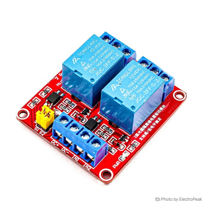
2-Channel Relay Module - 12V (High and Low Level Trigger)
$1.1300
In stock
SKU
REL-01-022
Volume discounts:
- +50 4 % $1.0800
- +100 6 % $1.0600
- +300 9 % $1.0300
- +500 11 % $1.0100
- +1000 13 % $0.9800
Product Variations:


Ships in 2-3 business days, then:
Free delivery in 12-15 days by Tracked Economic Shipping on orders over $100.
Free delivery in 7-10 days by Express Shipping on orders over $300.
More shipping info

Shop with confidence Learn More
 4-Channel Relay Module - 12V (High and Low Level Trigger) Previous
2-Channel 12V Relay Module Review
The 2-channel 12V relay module provides two independently controlled electromechanical switches for electronics, robotics, and low-voltage automation systems. Each channel includes jumper-selectable high- or low-level input triggering, status LEDs, and dedicated screw terminals for normally open and normally closed circuits. It suits bench prototypes and dual-load DC projects powered by a regulated 12V DC power supply. Do not choose it if you need guaranteed direct 3.3V logic switching, certified mains safety, or high-speed motor modulation.
The input circuit must be tested with your specific controller, so this module suits builders comfortable verifying trigger thresholds on the bench before permanent assembly. For projects requiring pre-documented logic isolation or solid-state operation, see our wider selection of relay and switching modules.
Specifications of 2-Channel Relay Module - 12V (High and Low Level Trigger)
- Type: Relay module
- Number of channels: 2 channel
- Operating voltage: 12V DC
- Working current: 190mA
- Trigger current: 3mA ~ 5mA
- Low-level trigger voltage: 0V ~ 1.5V
- High-level trigger voltage: 10~12V
- Load capacity: 10A at 250VAC or 30VDC
- Terminal block: Screw terminal block
- LED indicator: Yes
- Dimensions: 5x4.1x1.8 mm
- Weight: 33g
- DC+: Positive power supply
- DC-: Power negative
- xIN: Trigger signal input
- NO: Normally open relay output
- COM: Common relay output
- NC: Normally closed relay output
2-Channel 12V Relay Module Specifications Explained
To evaluate this module for a real-world build, consider how the published ratings affect physical wiring, logic levels, and load limits. Bench testing with a temporary control wiring for low-voltage testing kit helps verify these behaviors safely before final installation.
| Specification | Published Value | Why It Matters |
|---|---|---|
| Number of channels | 2 channel | Provides two fully independent single-pole double-throw (SPDT) electromechanical relays, allowing two separate circuits to be operated from independent control signals. |
| Operating voltage & current | 12V DC, 190mA | The relay coils require an external 12V DC power source connected to DC+ and DC-. They cannot be powered from microcontroller GPIO pins or standard 5V rails. |
| Trigger voltage ranges | Low: 0V ~ 1.5V; High: 10~12V | Changing the on-board jumper toggles the active trigger state. The wide gap between 1.5V and 10V means controller compatibility must be confirmed on the bench rather than assumed. |
| Trigger current | 3mA ~ 5mA | Represents the current drawn through the xIN control pin when activated, which fits within the drive capability of most standard digital interface stages. |
| Contact rating | 10A at 250VAC or 30VDC | This is a maximum resistive contact rating. Inductive loads like pumps, solenoids, and motors produce turn-off voltage spikes and inrush currents that require significant derating and external suppression. |
| Output terminals | NO, COM, NC | COM is the common contact. When the coil is de-energized, COM connects to NC (Normally Closed). When triggered, internal magnetic force pulls the armature to connect COM to NO (Normally Open). |
| Board dimensions | 5x4.1x1.8 mm | The published figure represents an unverified dimension entry; inspect and physically measure the received hardware before manufacturing or 3D printing custom enclosures. |
2-Channel 12V Relay Module Wiring and Compatibility
Powering and signaling this board means keeping coil power separate from control signals. The module needs an external 12V DC source connected directly to the DC+ and DC- terminals, capable of supplying the 190mA working current. Where an enclosure contains only a regulated 5V rail, a dual-channel relay board for regulated 5V systems avoids the need for a secondary supply.
Each xIN pin controls its corresponding channel. Set the jumper to HIGH to energize the channel when the input voltage reaches the high trigger threshold, published at 10~12V. In the LOW setting, the coil switches when the input is pulled between 0V and 1.5V. Documentation varies across generic boards, so do not assume direct 3.3V or 5V logic compatibility until you confirm trigger thresholds with your specific Arduino, ESP32, Raspberry Pi, or PLC output stage.
On the load side, wire external circuits in series through the COM terminal and either NO or NC. The relay is strictly a mechanical contact closure; it supplies no output voltage of its own. COM and NO leave the load disconnected until the trigger pin activates, while COM and NC keep the load powered whenever the module is idle or unpowered. The relay board itself needs no USB connection, firmware, device drivers, or communication libraries to function.
For bench testing and prototype hookups, use a dedicated regulated 12V DC power supply for board power and temporary control wiring for low-voltage testing jumpers for low-voltage signals.
2-Channel 12V Relay Module Limitations and Safety
This module provides straightforward dual-circuit on/off control, but several hardware constraints require careful engineering before permanent installation:
- Uncertain input thresholds: The published specifications list a 10~12V high-level trigger alongside a 0V~1.5V low-level trigger. Direct 3.3V GPIO driving from microcontrollers like the ESP32 or Raspberry Pi is not documented. If your setup requires verified low-voltage signaling, consider a board with listed 3.3V control support and four-channel 5V switching.
- No documented isolation: Optocoupler presence, trace creepage, and galvanic isolation ratings are unverified for this board. Do not treat the board as an isolated barrier between control electronics and hazardous lines.
- Resistive contact ratings: The 10A at 250VAC / 30VDC contact figure applies to purely resistive loads. Inductive elements such as fans, compressors, and linear actuators produce back-EMF arcing that can weld contacts shut unless snubbers, flyback diodes, or external contactors are added.
- Physical geometry: The listed 5x4.1x1.8 mm dimension is a catalog error for a dual electromechanical board. Always measure mounting-hole spacing and vertical clearance on the actual unit before ordering or machining an enclosure.
- High-voltage handling: Switching mains power requires appropriate fusing, grounded metal or fire-retardant enclosures, proper wire gauge, and mechanical strain relief. Hazardous voltages should only be serviced by qualified individuals.
2-Channel 12V Relay Module Alternatives
Circuit count, available power rails, and switching characteristics determine whether another switching module is a closer fit.
Channel Count and Logic Variations
Match the relay count to the number of circuits you need to avoid unnecessary board footprint:
- Single load: Use the one-channel 12V relay option for single-circuit designs with the same selectable high/low triggering. For systems using only active-low outputs, the compact fixed active-low relay option reduces enclosure footprint down to 43mm x 17mm.
- Four loads: The four-channel high/low-trigger relay option handles four independent circuits with selectable polarity. The four-channel fixed active-low switching board suits dedicated active-low logic buses.
- High-density control: Large automation setups can use the eight-channel relay control board with selectable triggering, or centralized high-channel-count relay control for up to 16 outputs from a unified 12V supply.
Alternative Switching Technologies
Mechanical relays use moving armatures, so they click audibly and have finite cycle lives. Different load types call for different switching technologies:
- Silent AC/DC switching: The silent solid-state switching for compatible loads module uses optotriac/semiconductor outputs to eliminate acoustic clicking and contact wear on supported loads.
- DC speed control and dimming: Mechanical armatures cannot handle pulse-width modulation. The PWM-capable DC motor and LED switching module drives 5–36V DC loads up to 15A at high switching frequencies.
- Wireless operation: For direct smartphone activation without writing microcode or wiring a controller, the Bluetooth-controlled two-channel switching board provides direct serial switching over short ranges.
2-Channel 12V Relay Module Setup Check
Follow this low-voltage verification sequence to confirm board operation and contact continuity before wiring higher-energy loads.
- Visual inspection: With all power disconnected, check terminal blocks for loose solder debris. Verify that the relay cans indicate a 12V DC coil rating and inspect the H/L jumper positions.
- Power connection: Connect a benchtop regulated 12V DC power supply to the DC+ (positive) and DC- (negative) screw terminals. Confirm that the on-board power LED illuminates.
- Jumper configuration: Place the selector jumper in the LOW position to test ground-referenced switching, using temporary control wiring for low-voltage testing leads.
- Continuity baseline: Set a digital multimeter to continuity mode. Touch the probes across COM and NC; the meter should indicate continuity. Touch COM and NO; the meter should show an open circuit.
- Trigger verification: Momentarily short the xIN pin to DC- for LOW trigger mode. The channel LED should light, the relay should produce an audible click, and the meter should show continuity between COM and NO while opening COM to NC. Repeat the test for the second channel.
- Load integration: Disconnect the 12V power supply before wiring external load circuits to the terminal blocks. Ensure appropriate fusing is placed in line with the load supply.
2-Channel 12V Relay Module FAQ and Buying Checklist
Does this 2-channel relay module need a 12V power supply?
Yes. The relay coils require a 12V DC supply connected to DC+ and DC- to operate. Microcontroller development boards cannot supply the 12V rail or the 190mA working current needed to energize the internal electromagnets. Power the module with a dedicated regulated 12V DC power supply.
Can an Arduino trigger this 12V relay module directly?
Direct Arduino compatibility is not guaranteed without testing because documented trigger thresholds conflict across generic production runs. The module lists a 10~12V high trigger and a 0~1.5V low trigger. Active-low jumper mode often responds to standard 5V digital pins pulling low, but you must verify voltage and current behavior on your specific board before finishing a design.
Will this relay module work directly with an ESP32 or Raspberry Pi?
Direct 3.3V logic compatibility is not documented for this board. A 3.3V GPIO output may fail to switch the input circuitry reliably or leave the input floating near switching thresholds. Use an external NPN transistor, a logic-level shifter, or select a dedicated 3.3V-compatible relay board instead.
What does high-level and low-level trigger mean on this 12V relay module?
The on-board jumper determines whether the relay energizes when the xIN pin receives a high signal or a low signal. In high-level mode, the relay switches on when the input sees a voltage between 10V and 12V. In low-level mode, it switches on when xIN is pulled down to 0V–1.5V.
Can both relays be controlled separately?
Yes. The module has two independent channels. Each channel has its own dedicated xIN control pin and output terminal set, allowing independent on/off operation from separate microcontroller signals.
What do NO, NC, and COM mean on the relay output?
COM is the common contact connected directly to the movable internal switch. NC (Normally Closed) remains connected to COM whenever the relay coil is off. NO (Normally Open) connects to COM only when the relay is triggered and energized.
Can this 10A relay module switch a pump, motor, heater, or 230V mains load?
The contacts carry a published rating of 10A at 250VAC or 30VDC for resistive loads, but inductive equipment requires substantial derating. Motors and pumps generate severe turn-off voltage spikes and startup inrush currents that can destroy bare relay contacts. Certified safety enclosures, arc suppression snubbers, and professional installation are mandatory for mains and high-energy loads.
Is this relay module optically isolated?
Optical isolation and separate ground topologies are not documented for this specific board. Do not assume galvanic isolation exists between the control inputs, board ground, and switching side.
Why does the relay click but the connected device stay off?
The relay functions solely as an isolated mechanical contact and does not output any voltage of its own. Confirm that your load circuit forms a closed loop including its own power source, wired in series through the COM and NO or NC terminals. Check contact continuity with a multimeter to verify that the contacts are closing.
Can this relay module dim an LED strip or control DC motor speed with PWM?
No. Electromechanical relays are limited to slow on/off switching and cannot respond to PWM frequencies. Attempting to PWM a mechanical relay causes rapid contact burning and mechanical failure. Use a PWM-capable DC motor and LED switching board for DC speed control and dimming tasks.
Purchase Decision Summary
- Ideal for: Dual-circuit automation, robotics, and prototype setups with an available 12V DC power rail that require basic on/off switching.
- Maybe for: Arduino and PLC systems where you can bench-test input thresholds and supply line suppression before permanent installation. If you only have a 5V power supply, choose a dual-channel relay board for regulated 5V systems instead.
- Avoid if: You need guaranteed direct 3.3V GPIO triggering, optical isolation certification, silent operation, PWM motor speed control, or documented high-inrush mains ratings. See our complete range of relay and switching modules for alternatives.
Buying Checklist
- Do you have a regulated 12V DC power source capable of at least 190mA?
- Have you verified whether your controller requires active-high or active-low trigger logic?
- Are you prepared to test trigger threshold compatibility if interfacing with 3.3V or 5V logic?
- Does your load circuit include an independent power supply wired through COM?
- Have you accounted for inrush current and inductive kickback if controlling motors or pumps?
- Do you have appropriate fuses, wire gauges, and protective enclosures planned?
- Have you planned to measure the physical board before fabricating custom enclosures?
| Interface Type | Digital |
|---|---|
| Operating Voltage (V) | 12V |
| Operating Current (mA) | 190 |
| Dimensions (mm) | 5x4.1x1.8 mm |
| Mounting Type | Screw holes |
| Control Type | Relay (Electromechanical) |
| Channel Count | 2 |
| Switching Capacity | 10A/250VAC or 10A/30VDC |
| Load Current (A) | 10 |
| Control Signal | Digital |
| LED Count | 2 |
| Relay Type | Relay output |
| Trigger Level | 0V ~ 1.5V (Low), 5V ~ 12V (High) |
| Display Type | LED |
| Material | PCB |
| Input Type (AC/DC) | DC |
| Weight (g) | 33 |
| Trigger Current | 3mA ~ 5mA |
Write Your Own Review

Please complete your information below to login.
Sign In
Create New Account