
Product added to cart

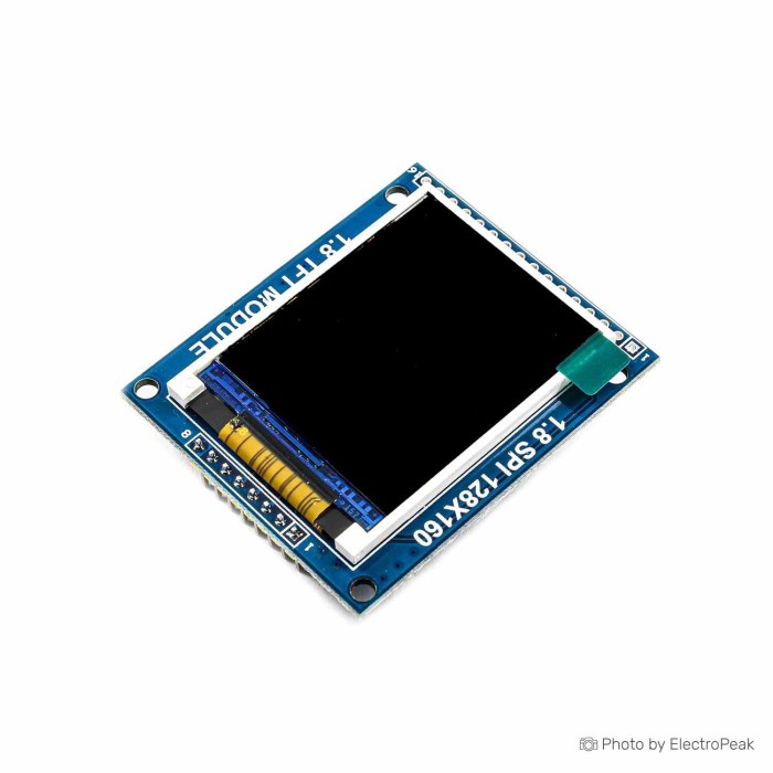
1.8 inch ST7735R SPI TFT LCD Display Module
$2.5800
In stock
SKU
LCD-01-062
Volume discounts:
- +25 4 % $2.4700
- +100 7 % $2.4100
- +300 9 % $2.3600
- +500 11 % $2.3000
- +1000 13 % $2.2500
Product Variations: View out of stock variants


Ships in 2-3 business days, then:
Free delivery in 12-15 days by Tracked Economic Shipping on orders over $100.
Free delivery in 7-10 days by Express Shipping on orders over $300.
More shipping info

Shop with confidence Learn More
 74HC59 4-Digit 7-Segment Display Module Previous
1.8 Inch ST7735R SPI TFT LCD Display Module Review
The 1.8 inch ST7735R SPI TFT LCD Display Module is a 128x160 full-color graphical display with an onboard SD card slot for microcontroller projects. It communicates over a serial peripheral interface (SPI) and suits compact user interfaces, telemetry displays, and bitmap rendering where monochrome indicators fall short. Direct connection to 5V logic systems requires external level shifting when onboard regulation is absent, and undocumented mechanical revisions require verification before the board is integrated into fixed production designs.
For bench testing and embedded prototyping, this screen offers an accessible way to add full-color graphics to microcontrollers. Detailed wiring steps are covered in our guide to interfacing the 1.8 inch ST7735 TFT display with Arduino, while broader options are available in our LCD display modules selection.
Specifications of 1.8 inch ST7735R SPI TFT LCD Display Module
- Type: TFT (Full Color)
- Driver IC: ST7735R
- Input Voltage: 5V
- Color: Full Color (262,144 colors)
- Screen Size: 1.8 inch
- Resolution: 128x160 pixels
- Interface: SPI
- PCB Size: 46mm x 50mm
- SD Card Slot: Yes
- Compatible With: Arduino and microcontrollers
- RESET: directly to the microcontroller IO
- CS: directly to the microcontroller IO
- A0: IO control registers select
- SDA: IO control data transmission
- SCL: IO control SPI bus
- BL: High-Level 3.3V backlight on
1.8 Inch ST7735R SPI TFT LCD Display Module Specifications Explained
The electrical and physical specifications translate directly into practical project constraints. The table below explains what each critical specification means in use.
| Specification | Value | Why It Matters |
|---|---|---|
| Resolution & Size | 128x160 pixels, 1.8 inch | Provides sufficient pixel density for status readouts, small icons, multi-line sensor readouts, and menus. It is not intended for dense, high-resolution user interfaces. |
| Color Depth | Full Color (262,144 colors) | Allows full RGB color rendering, enabling color-coded alarm thresholds, graphical gauges, and full-color bitmap images rather than monochrome text. |
| Bus Interface | SPI (SDA / SCL labels) | Uses synchronous SPI communication. Despite the SDA and SCL silkscreen markings, this is an SPI interface where SDA carries data output (MOSI) and SCL serves as the clock line, not an I2C bus. |
| Frame Buffer & I/O Count | Pixel-addressable internal buffer | The internal display RAM offloads rendering refresh tasks from the host microcontroller, enabling basic display operation using as few as 4 digital I/O lines. |
| Storage Expansion | Integrated SD Card Slot | Enables loading raw bitmaps and icon assets directly from removable flash storage, preserving the microcontroller's internal program memory. |
| Physical Footprint | 46mm x 50mm PCB | Defines overall space requirements for custom panels. Because exact mounting-hole patterns are not documented, enclosure designers should measure the board on arrival before finalizing custom cutouts. |
Where space is limited and a square aspect ratio is preferred, the 1.44" TFT LCD (128x128) offers a smaller footprint with a similar ST7735-family driver.
1.8 Inch ST7735R SPI TFT LCD Arduino Compatibility
The module connects to SPI-capable microcontrollers and operates natively at 3.3V logic levels. Although the board specification lists an input voltage of 5V, the signal lines communicate at 3.3V. With a 5V microcontroller such as an Arduino Uno R3 (Clone), use a bidirectional or unidirectional logic level converter on the digital control lines unless your module includes onboard level-shifting circuitry.
The display interface exposes six primary control pins: RESET, CS (Chip Select), A0 (Register / Data select), SDA (Data transmission / MOSI), SCL (Clock / SCK), and BL (Backlight control). SDA and SCL connect to your hardware SPI bus, not the microcontroller's I2C pins. A 3.3V high signal on BL switches the backlight on. Do not tie BL directly to 5V rails without confirming regulation.
The onboard SD card slot needs connections beyond the six display control pins. The TFT controller is receive-only, but reading data from an SD card requires a SPI MISO (Master In Slave Out) line and a dedicated, separate card chip-select (CS) connection. For reliable breadboard prototyping, use secure connections with quality male/female jumper wires. For more wiring configurations, consult our technical overview of interfacing the 1.8 inch SPI TFT color display module with Arduino.
For projects that only need basic diagnostic text and benefit from conserving microcontroller pins with a native two-wire interface, consider the 0.96" Yellow/Blue I2C OLED as an alternative approach.
1.8 Inch ST7735R SPI TFT LCD Display Module Limitations
This unbranded display module has hardware constraints that can cause design delays or component damage:
- 5V Logic Vulnerability: The module input voltage is rated at 5V, but signal pins operate at 3.3V. Connecting signal lines directly to 5V logic without verifying onboard regulation or using level shifters can lead to premature display failure.
- Silkscreen Misidentification: The display lines are marked SDA and SCL. Users unfamiliar with this pinout frequently mistake them for I2C pins, leading to non-functional wiring.
- Driver Initialization Variations: While specified with an ST7735R controller, generic modules can occasionally feature minor silicon revisions within the ST7735 family. Incompatible software initialization can cause inverted colors, shifted pixel offsets, or incorrect display orientation.
- Backlight Dimming: The specification defines BL strictly as high-level 3.3V for backlight activation. The board does not document onboard transistor switching or PWM dimming support.
- Mechanical and Sourcing Consistency: Mechanical drawings, exact mounting hole placements, and PCB revision numbers are not documented. This makes the module well-suited for prototypes and hobby projects, but less suitable for production runs requiring strict revision control.
Test the panel, color rendering, and SD card functionality upon delivery before permanently mounting the module in an enclosure.
1.8 Inch ST7735R TFT vs 1.44 Inch TFT and I2C OLED
Your enclosure constraints, available communication bus, and color requirements determine the appropriate display. The table below compares this 1.8-inch module with alternative options from our catalog.
| Feature | 1.8" ST7735R SPI TFT | 1.44" ST7735S SPI TFT | 0.96" SSD1306 I2C OLED |
|---|---|---|---|
| Screen Size & Shape | 1.8 inch rectangular | 1.44 inch square | 0.96 inch rectangular |
| Resolution | 128x160 pixels | 128x128 pixels | 128x64 pixels |
| Color Capability | Full Color (262k colors) | Full Color (ST7735S) | Two-color (Yellow and Blue sections) |
| Interface | SPI (Header pins) | SPI (14-pin FPC, 0.8mm pitch) | I2C (4-pin header) |
| Integrated SD Slot | Yes | No | No |
| Best Application | Color dashboards, bitmap display | Compact wearables, tight enclosures | Low-power readouts, minimal wiring |
A smaller square form factor points to the 1.44" TFT LCD (128x128), which uses FPC ribbon termination. Where color graphics and SD storage are unnecessary, the 0.96" Yellow/Blue I2C OLED uses a standard two-wire I2C interface. More display technologies are available in our LCD display modules section.
1.8 Inch ST7735R SPI TFT LCD Display Module Accessories
This SPI display module needs supporting hardware for power, communication, and prototyping:
- Required Microcontroller: Use an SPI-capable development board, such as the Arduino Uno R3 (Clone), ESP32, or STM32 board, to generate signals and supply power.
- Required Wiring: Use flexible male/female jumper wires to route SPI, power, and reset connections between the display and your controller.
- Required for 5V Logic: Add a logic level converter when connecting to 5V microcontrollers such as standard ATmega328P boards, ensuring data lines are safely stepped down to 3.3V.
- Recommended Prototyping Platform: An external breadboard, such as the SYB-500 Breadboard, provides an organized layout for level shifters, power distribution, and display headers.
- Recommended for Bitmap Storage: Use a standard micro SD card formatted to FAT16 or FAT32 when your project requires loading external image files.
- Optional Diagnostic Tools: A digital multimeter can verify 3.3V rail stability and check signal continuity across breadboard tracks.
1.8 Inch ST7735R SPI TFT LCD Arduino Quick Start
Use this procedure to verify basic display operation when the module arrives:
- Confirm Logic Levels: If using a 5V controller such as the Arduino Uno R3 (Clone), route your signal lines through a 3.3V logic level converter.
- Connect Power and Control Pins: Using male/female jumper wires, wire the display power pins to 5V and GND. Connect RESET and CS to digital output pins, and route BL to a 3.3V rail.
- Connect SPI Bus: Wire SDA to your microcontroller's hardware SPI MOSI pin, SCL to SPI SCK, and A0 to an available digital output.
- Configure Graphics Library: In the Arduino IDE, install an ST7735-compatible library, such as Adafruit_ST7735 or TFT_eSPI. Select the ST7735R initialization profile in the library setup.
- Run a Test Sketch: Upload a basic graphics test sketch. The screen should immediately render distinct color patterns, rectangles, and text lines across the 128x160 area.
- Verify SD Card Operation (Optional): To read bitmap images, connect the separate SD card CS line to a spare digital pin and connect the SD MISO line to the microcontroller SPI MISO pin. Ensure the card is formatted as FAT16 or FAT32.
Common first-power-on issues include a completely black screen caused by leaving the BL pin disconnected, garbled or inverted colors indicating an incorrect ST7735 profile selection in code, and communication failure caused by wiring SDA/SCL to hardware I2C pins instead of SPI lines. For detailed code examples, see our tutorial on interfacing the 1.8 inch ST7735 TFT display with Arduino.
Frequently Asked Questions
Is this 1.8 inch ST7735R TFT display 3.3V or 5V?
The module lists an input power supply voltage of 5V, but the ST7735R controller logic operates at 3.3V. Use an external logic level converter on data lines when interfacing with 5V microcontrollers unless your specific module is verified to include onboard level shifting.
Does SDA/SCL mean this ST7735R display uses I2C?
No, this display uses an SPI bus. The silkscreen labels SDA as serial data (MOSI) and SCL as the serial clock (SCK), so both must connect to SPI pins on your controller.
Which library works with the ST7735R SPI TFT module?
Adafruit_ST7735 and TFT_eSPI provide established support for this hardware. Configure the driver initialization specifically for the ST7735R controller to avoid pixel offsets or color inversion.
Does the SD-card slot work using only the listed display pins?
No, the SD card interface requires its own SPI connections. In addition to sharing the SPI clock and data lines, connect a dedicated chip select (CS) line for the card and route the MISO line back to your microcontroller.
Can I use this display with an Arduino Uno?
Yes, the display works with an Arduino Uno over SPI. Because the Uno operates at 5V logic, run the control lines through a level shifter to protect the display controller.
Can I PWM-dim the BL backlight pin?
The specification states that the BL pin requires a high-level 3.3V signal to illuminate the backlight. Onboard transistor support and PWM dimming capability are not documented for this board, so PWM dimming remains unverified.
What are the board dimensions for an enclosure?
The PCB measures 46mm by 50mm. Because mounting-hole coordinates and tolerances are not documented, measure your physical board before fabricating custom enclosures or 3D-printed faceplates.
Purchase Decision Summary
| Category | Assessment |
|---|---|
| Ideal For | Microcontroller projects requiring a compact 1.8-inch full-color SPI display, 128x160 resolution, and integrated SD card storage for loading graphics assets and telemetry menus. |
| Suitable With Adjustments | Beginners building Arduino prototypes who are prepared to wire SPI connections, install ST7735 libraries, and integrate logic level shifters for 5V systems. |
| Consider Another Option If | Your deployment requires native 5V-tolerant signal pins, guaranteed PWM backlight dimming, strict revision-controlled mechanical drawings, or verified production-grade traceability. |
Buying Checklist
- Verify that the 1.8-inch 128x160 resolution satisfies your user interface and text layout requirements.
- Ensure your host microcontroller has sufficient SPI-capable I/O pins available.
- Plan for a 3.3V logic level converter if you are using an Arduino Uno or other 5V development board.
- Confirm that you need full-color RGB output rather than a lower-pin-count monochrome or two-color OLED display.
- Account for separate MISO and card CS connections if your project uses the onboard SD card socket.
- Procure jumper wires, a breadboard, and a FAT16/FAT32 formatted micro SD card separately, as these accessories are not included with the module.
- Plan to verify display output and physical PCB dimensions on your bench before finalizing mounting brackets or enclosure designs.
| Display Size | 1.8 |
|---|---|
| Display Size Range | 1 inch to 1.99 inch |
| Display Resolution | 128*160 |
| Display Driver | ST7735R |
| Display Interface | SPI |
| Display Color Type | Full Color |
| Touchscreen Type | None |
| Backlight Type | White LED |
| Operating Voltage (V) | 3.3V |
| Pins | 4 |
| Dimensions (mm) | 54mm x 45mm; 45x35x3 mm |
Write Your Own Review

Please complete your information below to login.
Sign In
Create New Account