
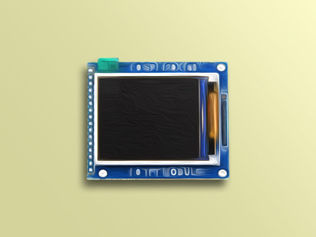
ST7735R 1.8 Inch TFT Display Features
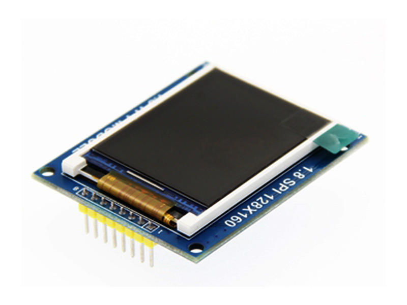
The TFT display is a kind of liquid crystal LCD that is connected to each pixel using a transistor and it features low current consumption, high-quality, high-resolution and backlight. This 1.8-inch full color LCD has a narrow PCB screen. The resolution is 128×160 pixels and it has a four-wire SPI interface and white backlight. The driver is ST7735R.
This display also has a SD card slot.
Note
The operating voltage of this module is 3.3V and a voltage divider is required to interface it with Arduino.
To download datasheet and for more details, refer to link below.
http://www.lcdwiki.com/1.8inch_SPI_Module_ST7735S_SKU:MSP1804
Download the datasheet of this module here.
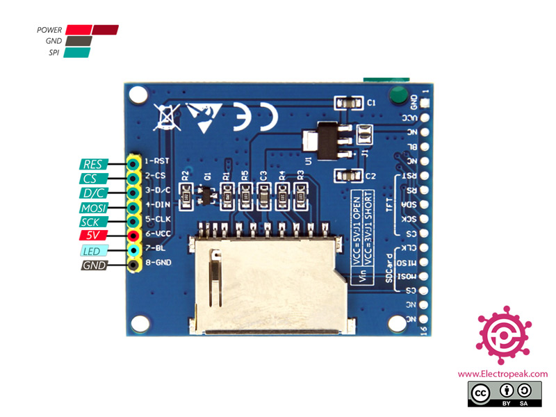
ST7735R 1.8 Inch TFT Display Pinout
This module has 13 pins:
- VIN: Module power supply – 3.3-5V
- GND: Ground
- RST: LCD reset
- CS: LCD chip select signal, for SPI protocol
- D/C: Data selection signal
- MOSI: SPI bus write data signal
- MISO: SPI bus read data signal
- SCK: SPI bus clock signal
- LED+: Backlight control (Positive power supply)
- LED-: Backlight control (Negative power supply)
You can see the pinout of this module in the image below.
Required Material
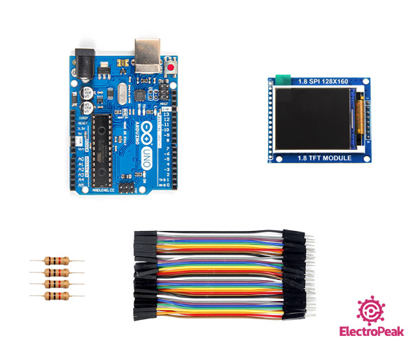
Hardware component
Software Apps
Interfacing ST7735R 1.8 Inch TFT Display with Arduino
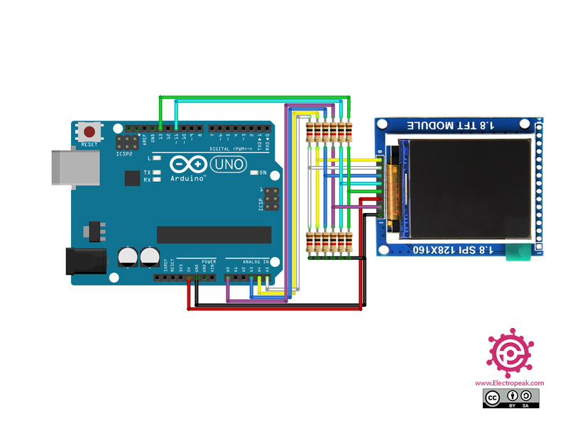
Step 1: Circuit
The following circuit shows how you should connect Arduino to this Display. Connect wires accordingly.
Step 2: Library
First, install the following libraries on Arduino IDE.
Tip
If you need more help with installing a library on Arduino, read this tutorial: How to Install an Arduino Library
Step 3: Code
Upload the following code to your Arduino.
   /***************************************************
  This is a library for the Adafruit 1.8" SPI display.

This library works with the Adafruit 1.8" TFT Breakout w/SD card
  ----> http://www.adafruit.com/products/358
The 1.8" TFT shield
  ----> https://www.adafruit.com/product/802
The 1.44" TFT breakout
  ----> https://www.adafruit.com/product/2088
as well as Adafruit raw 1.8" TFT display
  ----> http://www.adafruit.com/products/618

  Check out the links above for our tutorials and wiring diagrams
  These displays use SPI to communicate, 4 or 5 pins are required to
  interface (RST is optional)
  Adafruit invests time and resources providing this open source code,
  please support Adafruit and open-source hardware by purchasing
  products from Adafruit!

  Written by Limor Fried/Ladyada for Adafruit Industries.
  MIT license, all text above must be included in any redistribution
 ****************************************************/

#include <Adafruit_GFX.h>    // Core graphics library
#include <Adafruit_ST7735.h> // Hardware-specific library
#include <SPI.h>


// For the breakout, you can use any 2 or 3 pins
// These pins will also work for the 1.8" TFT shield
#define TFT_CS     10
#define TFT_RST    9  // you can also connect this to the Arduino reset
                      // in which case, set this #define pin to -1!
#define TFT_DC     8

// Option 1 (recommended): must use the hardware SPI pins
// (for UNO thats sclk = 13 and sid = 11) and pin 10 must be
// an output. This is much faster - also required if you want
// to use the microSD card (see the image drawing example)
Adafruit_ST7735 tft = Adafruit_ST7735(TFT_CS,  TFT_DC, TFT_RST);

// Option 2: use any pins but a little slower!
#define TFT_SCLK 13   // set these to be whatever pins you like!
#define TFT_MOSI 11   // set these to be whatever pins you like!
//Adafruit_ST7735 tft = Adafruit_ST7735(TFT_CS, TFT_DC, TFT_MOSI, TFT_SCLK, TFT_RST);


float p = 3.1415926;

void setup(void) {
  Serial.begin(9600);
  Serial.print("Hello! ST7735 TFT Test");

  // Use this initializer if you're using a 1.8" TFT
  tft.initR(INITR_BLACKTAB);   // initialize a ST7735S chip, black tab

  // Use this initializer (uncomment) if you're using a 1.44" TFT
  //tft.initR(INITR_144GREENTAB);   // initialize a ST7735S chip, black tab

  // Use this initializer (uncomment) if you're using a 0.96" 180x60 TFT
  //tft.initR(INITR_MINI160x80);   // initialize a ST7735S chip, mini display

  Serial.println("Initialized");

  uint16_t time = millis();
  tft.fillScreen(ST7735_BLACK);
  time = millis() - time;

  Serial.println(time, DEC);
  delay(500);

  // large block of text
  tft.fillScreen(ST7735_BLACK);
  testdrawtext("Lorem ipsum dolor sit amet, consectetur adipiscing elit. Curabitur adipiscing ante sed nibh tincidunt feugiat. Maecenas enim massa, fringilla sed malesuada et, malesuada sit amet turpis. Sed porttitor neque ut ante pretium vitae malesuada nunc bibendum. Nullam aliquet ultrices massa eu hendrerit. Ut sed nisi lorem. In vestibulum purus a tortor imperdiet posuere. ", ST7735_WHITE);
  delay(1000);

  // tft print function!
  tftPrintTest();
  delay(4000);

  // a single pixel
  tft.drawPixel(tft.width()/2, tft.height()/2, ST7735_GREEN);
  delay(500);

  // line draw test
  testlines(ST7735_YELLOW);
  delay(500);

  // optimized lines
  testfastlines(ST7735_RED, ST7735_BLUE);
  delay(500);

  testdrawrects(ST7735_GREEN);
  delay(500);

  testfillrects(ST7735_YELLOW, ST7735_MAGENTA);
  delay(500);

  tft.fillScreen(ST7735_BLACK);
  testfillcircles(10, ST7735_BLUE);
  testdrawcircles(10, ST7735_WHITE);
  delay(500);

  testroundrects();
  delay(500);

  testtriangles();
  delay(500);

  mediabuttons();
  delay(500);

  Serial.println("done");
  delay(1000);
}

void loop() {
  tft.invertDisplay(true);
  delay(500);
  tft.invertDisplay(false);
  delay(500);
}

void testlines(uint16_t color) {
  tft.fillScreen(ST7735_BLACK);
  for (int16_t x=0; x < tft.width(); x+=6) {
    tft.drawLine(0, 0, x, tft.height()-1, color);
  }
  for (int16_t y=0; y < tft.height(); y+=6) {
    tft.drawLine(0, 0, tft.width()-1, y, color);
  }

  tft.fillScreen(ST7735_BLACK);
  for (int16_t x=0; x < tft.width(); x+=6) {
    tft.drawLine(tft.width()-1, 0, x, tft.height()-1, color);
  }
  for (int16_t y=0; y < tft.height(); y+=6) {
    tft.drawLine(tft.width()-1, 0, 0, y, color);
  }

  tft.fillScreen(ST7735_BLACK);
  for (int16_t x=0; x < tft.width(); x+=6) {
    tft.drawLine(0, tft.height()-1, x, 0, color);
  }
  for (int16_t y=0; y < tft.height(); y+=6) {
    tft.drawLine(0, tft.height()-1, tft.width()-1, y, color);
  }

  tft.fillScreen(ST7735_BLACK);
  for (int16_t x=0; x < tft.width(); x+=6) {
    tft.drawLine(tft.width()-1, tft.height()-1, x, 0, color);
  }
  for (int16_t y=0; y < tft.height(); y+=6) {
    tft.drawLine(tft.width()-1, tft.height()-1, 0, y, color);
  }
}

void testdrawtext(char *text, uint16_t color) {
  tft.setCursor(0, 0);
  tft.setTextColor(color);
  tft.setTextWrap(true);
  tft.print(text);
}

void testfastlines(uint16_t color1, uint16_t color2) {
  tft.fillScreen(ST7735_BLACK);
  for (int16_t y=0; y < tft.height(); y+=5) {
    tft.drawFastHLine(0, y, tft.width(), color1);
  }
  for (int16_t x=0; x < tft.width(); x+=5) {
    tft.drawFastVLine(x, 0, tft.height(), color2);
  }
}

void testdrawrects(uint16_t color) {
  tft.fillScreen(ST7735_BLACK);
  for (int16_t x=0; x < tft.width(); x+=6) {
    tft.drawRect(tft.width()/2 -x/2, tft.height()/2 -x/2 , x, x, color);
  }
}

void testfillrects(uint16_t color1, uint16_t color2) {
  tft.fillScreen(ST7735_BLACK);
  for (int16_t x=tft.width()-1; x > 6; x-=6) {
    tft.fillRect(tft.width()/2 -x/2, tft.height()/2 -x/2 , x, x, color1);
    tft.drawRect(tft.width()/2 -x/2, tft.height()/2 -x/2 , x, x, color2);
  }
}

void testfillcircles(uint8_t radius, uint16_t color) {
  for (int16_t x=radius; x < tft.width(); x+=radius*2) {
    for (int16_t y=radius; y < tft.height(); y+=radius*2) {
      tft.fillCircle(x, y, radius, color);
    }
  }
}

void testdrawcircles(uint8_t radius, uint16_t color) {
  for (int16_t x=0; x < tft.width()+radius; x+=radius*2) {
    for (int16_t y=0; y < tft.height()+radius; y+=radius*2) {
      tft.drawCircle(x, y, radius, color);
    }
  }
}

void testtriangles() {
  tft.fillScreen(ST7735_BLACK);
  int color = 0xF800;
  int t;
  int w = tft.width()/2;
  int x = tft.height()-1;
  int y = 0;
  int z = tft.width();
  for(t = 0 ; t <= 15; t++) {
    tft.drawTriangle(w, y, y, x, z, x, color);
    x-=4;
    y+=4;
    z-=4;
    color+=100;
  }
}

void testroundrects() {
  tft.fillScreen(ST7735_BLACK);
  int color = 100;
  int i;
  int t;
  for(t = 0 ; t <= 4; t+=1) {
    int x = 0;
    int y = 0;
    int w = tft.width()-2;
    int h = tft.height()-2;
    for(i = 0 ; i <= 16; i+=1) {
      tft.drawRoundRect(x, y, w, h, 5, color);
      x+=2;
      y+=3;
      w-=4;
      h-=6;
      color+=1100;
    }
    color+=100;
  }
}

void tftPrintTest() {
  tft.setTextWrap(false);
  tft.fillScreen(ST7735_BLACK);
  tft.setCursor(0, 30);
  tft.setTextColor(ST7735_RED);
  tft.setTextSize(1);
  tft.println("Hello World!");
  tft.setTextColor(ST7735_YELLOW);
  tft.setTextSize(2);
  tft.println("Hello World!");
  tft.setTextColor(ST7735_GREEN);
  tft.setTextSize(3);
  tft.println("Hello World!");
  tft.setTextColor(ST7735_BLUE);
  tft.setTextSize(4);
  tft.print(1234.567);
  delay(1500);
  tft.setCursor(0, 0);
  tft.fillScreen(ST7735_BLACK);
  tft.setTextColor(ST7735_WHITE);
  tft.setTextSize(0);
  tft.println("Hello World!");
  tft.setTextSize(1);
  tft.setTextColor(ST7735_GREEN);
  tft.print(p, 6);
  tft.println(" Want pi?");
  tft.println(" ");
  tft.print(8675309, HEX); // print 8,675,309 out in HEX!
  tft.println(" Print HEX!");
  tft.println(" ");
  tft.setTextColor(ST7735_WHITE);
  tft.println("Sketch has been");
  tft.println("running for: ");
  tft.setTextColor(ST7735_MAGENTA);
  tft.print(millis() / 1000);
  tft.setTextColor(ST7735_WHITE);
  tft.print(" seconds.");
}

void mediabuttons() {
  // play
  tft.fillScreen(ST7735_BLACK);
  tft.fillRoundRect(25, 10, 78, 60, 8, ST7735_WHITE);
  tft.fillTriangle(42, 20, 42, 60, 90, 40, ST7735_RED);
  delay(500);
  // pause
  tft.fillRoundRect(25, 90, 78, 60, 8, ST7735_WHITE);
  tft.fillRoundRect(39, 98, 20, 45, 5, ST7735_GREEN);
  tft.fillRoundRect(69, 98, 20, 45, 5, ST7735_GREEN);
  delay(500);
  // play color
  tft.fillTriangle(42, 20, 42, 60, 90, 40, ST7735_BLUE);
  delay(50);
  // pause color
  tft.fillRoundRect(39, 98, 20, 45, 5, ST7735_RED);
  tft.fillRoundRect(69, 98, 20, 45, 5, ST7735_RED);
  // play color
  tft.fillTriangle(42, 20, 42, 60, 90, 40, ST7735_GREEN);

}
This code is for testing the display and shows various graphical shapes and designs.

Comment (1)
Perfect I have tested with an ST7735 greentab and connected to an ESP32 (38pin), and it works all only i had to adapt few lines in order to use my own hardware.
Remember to put the rigth configurantion inside User_setup.h
// For the breakout, you can use any 2 or 3 pins
// These pins will also work for the 1.8″ TFT shield
#define TFT_CS 15
#define TFT_RST 4 // you can also connect this to the Arduino reset
// in which case, set this #define pin to -1!
#define TFT_DC 2
Only an small advice for those who want to rotate to rotate the text you have to use the instruction tft.setRotation (2); the number can be 0,1,2,3
this is my program
tft.setRotation (2);
uint16_t time = millis();
tft.fillScreen(ST7735_BLACK);
time = millis() – time;
Serial.println(time, DEC);
delay(500);
here is my user setup .h
// USER DEFINED SETTINGS
// Set driver type, fonts to be loaded, pins used and SPI control method etc
//
// See the User_Setup_Select.h file if you wish to be able to define multiple
// setups and then easily select which setup file is used by the compiler.
//
// If this file is edited correctly then all the library example sketches should
// run without the need to make any more changes for a particular hardware setup!
// Note that some sketches are designed for a particular TFT pixel width/height
// User defined information reported by “Read_User_Setup” test & diagnostics example
#define USER_SETUP_INFO “User_Setup”
// Define to disable all #warnings in library (can be put in User_Setup_Select.h)
//#define DISABLE_ALL_LIBRARY_WARNINGS
// ##################################################################################
//
// Section 1. Call up the right driver file and any options for it
//
// ##################################################################################
// Define STM32 to invoke optimised processor support (only for STM32)
//#define STM32
// Defining the STM32 board allows the library to optimise the performance
// for UNO compatible “MCUfriend” style shields
//#define NUCLEO_64_TFT
//#define NUCLEO_144_TFT
// STM32 8 bit parallel only:
// If STN32 Port A or B pins 0-7 are used for 8 bit parallel data bus bits 0-7
// then this will improve rendering performance by a factor of ~8x
//#define STM_PORTA_DATA_BUS
//#define STM_PORTB_DATA_BUS
// Tell the library to use parallel mode (otherwise SPI is assumed)
//#define TFT_PARALLEL_8_BIT
//#defined TFT_PARALLEL_16_BIT // **** 16 bit parallel ONLY for RP2040 processor ****
// Display type – only define if RPi display
//#define RPI_DISPLAY_TYPE // 20MHz maximum SPI
// Only define one driver, the other ones must be commented out
//#define ILI9341_DRIVER // Generic driver for common displays
//#define ILI9341_2_DRIVER // Alternative ILI9341 driver, see https://github.com/Bodmer/TFT_eSPI/issues/1172
#define ST7735_DRIVER // Define additional parameters below for this display
//#define ILI9163_DRIVER // Define additional parameters below for this display
//#define S6D02A1_DRIVER
//#define RPI_ILI9486_DRIVER // 20MHz maximum SPI
//#define HX8357D_DRIVER
//#define ILI9481_DRIVER
//#define ILI9486_DRIVER
//#define ILI9488_DRIVER // WARNING: Do not connect ILI9488 display SDO to MISO if other devices share the SPI bus (TFT SDO does NOT tristate when CS is high)
//#define ST7789_DRIVER // Full configuration option, define additional parameters below for this display
//#define ST7789_2_DRIVER // Minimal configuration option, define additional parameters below for this display
//#define R61581_DRIVER
//#define RM68140_DRIVER
//#define ST7796_DRIVER
//#define SSD1351_DRIVER
//#define SSD1963_480_DRIVER
//#define SSD1963_800_DRIVER
//#define SSD1963_800ALT_DRIVER
//#define ILI9225_DRIVER
//#define GC9A01_DRIVER
// Some displays support SPI reads via the MISO pin, other displays have a single
// bi-directional SDA pin and the library will try to read this via the MOSI line.
// To use the SDA line for reading data from the TFT uncomment the following line:
//#define TFT_SDA_READ // This option is for ESP32 ONLY, tested with ST7789 and GC9A01 display only
// For ST7735, ST7789 and ILI9341 ONLY, define the colour order IF the blue and red are swapped on your display
// Try ONE option at a time to find the correct colour order for your display
#define TFT_RGB_ORDER TFT_RGB // Colour order Red-Green-Blue
// #define TFT_RGB_ORDER TFT_BGR // Colour order Blue-Green-Red
// For M5Stack ESP32 module with integrated ILI9341 display ONLY, remove // in line below
// #define M5STACK
// For ST7789, ST7735, ILI9163 and GC9A01 ONLY, define the pixel width and height in portrait orientation
// #define TFT_WIDTH 80
#define TFT_WIDTH 128
// #define TFT_WIDTH 172 // ST7789 172 x 320
// #define TFT_WIDTH 240 // ST7789 240 x 240 and 240 x 320
#define TFT_HEIGHT 160
// #define TFT_HEIGHT 128
// #define TFT_HEIGHT 240 // ST7789 240 x 240
// #define TFT_HEIGHT 320 // ST7789 240 x 320
// #define TFT_HEIGHT 240 // GC9A01 240 x 240
// For ST7735 ONLY, define the type of display, originally this was based on the
// colour of the tab on the screen protector film but this is not always true, so try
// out the different options below if the screen does not display graphics correctly,
// e.g. colours wrong, mirror images, or stray pixels at the edges.
// Comment out ALL BUT ONE of these options for a ST7735 display driver, save this
// this User_Setup file, then rebuild and upload the sketch to the board again:
//#define ST7735_INITB
//#define ST7735_GREENTAB
#define ST7735_GREENTAB2
//#define ST7735_GREENTAB3
//#define ST7735_GREENTAB128 // For 128 x 128 display
//#define ST7735_GREENTAB160x80 // For 160 x 80 display (BGR, inverted, 26 offset)
//#define ST7735_ROBOTLCD // For some RobotLCD arduino shields (128×160, BGR, https://docs.arduino.cc/retired/getting-started-guides/TFT)
//#define ST7735_REDTAB
//#define ST7735_BLACKTAB
//#define ST7735_REDTAB160x80 // For 160 x 80 display with 24 pixel offset
// If colours are inverted (white shows as black) then uncomment one of the next
// 2 lines try both options, one of the options should correct the inversion.
// #define TFT_INVERSION_ON
#define TFT_INVERSION_OFF
// ##################################################################################
//
// Section 2. Define the pins that are used to interface with the display here
//
// ##################################################################################
// If a backlight control signal is available then define the TFT_BL pin in Section 2
// below. The backlight will be turned ON when tft.begin() is called, but the library
// needs to know if the LEDs are ON with the pin HIGH or LOW. If the LEDs are to be
// driven with a PWM signal or turned OFF/ON then this must be handled by the user
// sketch. e.g. with digitalWrite(TFT_BL, LOW);
// #define TFT_BL 32 // LED back-light control pin
// #define TFT_BACKLIGHT_ON HIGH // Level to turn ON back-light (HIGH or LOW)
// We must use hardware SPI, a minimum of 3 GPIO pins is needed.
// Typical setup for ESP8266 NodeMCU ESP-12 is :
//
// Display SDO/MISO to NodeMCU pin D6 (or leave disconnected if not reading TFT)
// Display LED to NodeMCU pin VIN (or 5V, see below)
// Display SCK to NodeMCU pin D5
// Display SDI/MOSI to NodeMCU pin D7
// Display DC (RS/AO)to NodeMCU pin D3
// Display RESET to NodeMCU pin D4 (or RST, see below)
// Display CS to NodeMCU pin D8 (or GND, see below)
// Display GND to NodeMCU pin GND (0V)
// Display VCC to NodeMCU 5V or 3.3V
//
// The TFT RESET pin can be connected to the NodeMCU RST pin or 3.3V to free up a control pin
//
// The DC (Data Command) pin may be labelled AO or RS (Register Select)
//
// With some displays such as the ILI9341 the TFT CS pin can be connected to GND if no more
// SPI devices (e.g. an SD Card) are connected, in this case comment out the #define TFT_CS
// line below so it is NOT defined. Other displays such at the ST7735 require the TFT CS pin
// to be toggled during setup, so in these cases the TFT_CS line must be defined and connected.
//
// The NodeMCU D0 pin can be used for RST
//
//
// Note: only some versions of the NodeMCU provide the USB 5V on the VIN pin
// If 5V is not available at a pin you can use 3.3V but backlight brightness
// will be lower.
// ###### EDIT THE PIN NUMBERS IN THE LINES FOLLOWING TO SUIT YOUR ESP8266 SETUP ######
// For NodeMCU – use pin numbers in the form PIN_Dx where Dx is the NodeMCU pin designation
//#define TFT_CS PIN_D8 // Chip select control pin D8
//#define TFT_DC PIN_D3 // Data Command control pin
//#define TFT_RST PIN_D4 // Reset pin (could connect to NodeMCU RST, see next line)
//#define TFT_RST -1 // Set TFT_RST to -1 if the display RESET is connected to NodeMCU RST or 3.3V
//#define TFT_BL PIN_D1 // LED back-light (only for ST7789 with backlight control pin)
//#define TOUCH_CS PIN_D2 // Chip select pin (T_CS) of touch screen
//#define TFT_WR PIN_D2 // Write strobe for modified Raspberry Pi TFT only
// ###### FOR ESP8266 OVERLAP MODE EDIT THE PIN NUMBERS IN THE FOLLOWING LINES ######
// Overlap mode shares the ESP8266 FLASH SPI bus with the TFT so has a performance impact
// but saves pins for other functions. It is best not to connect MISO as some displays
// do not tristate that line when chip select is high!
// Note: Only one SPI device can share the FLASH SPI lines, so a SPI touch controller
// cannot be connected as well to the same SPI signals.
// On NodeMCU 1.0 SD0=MISO, SD1=MOSI, CLK=SCLK to connect to TFT in overlap mode
// On NodeMCU V3 S0 =MISO, S1 =MOSI, S2 =SCLK
// In ESP8266 overlap mode the following must be defined
//#define TFT_SPI_OVERLAP
// In ESP8266 overlap mode the TFT chip select MUST connect to pin D3
//#define TFT_CS PIN_D3
//#define TFT_DC PIN_D5 // Data Command control pin
//#define TFT_RST PIN_D4 // Reset pin (could connect to NodeMCU RST, see next line)
//#define TFT_RST -1 // Set TFT_RST to -1 if the display RESET is connected to NodeMCU RST or 3.3V
// ###### EDIT THE PIN NUMBERS IN THE LINES FOLLOWING TO SUIT YOUR ESP32 SETUP ######
// For ESP32 Dev board (only tested with ILI9341 display)
// The hardware SPI can be mapped to any pins
//#define TFT_MISO 19
//#define TFT_MOSI 23
//#define TFT_SCLK 18
//#define TFT_CS 15 // Chip select control pin
//#define TFT_DC 2 // Data Command control pin
//#define TFT_RST 4 // Reset pin (could connect to RST pin)
//#define TFT_RST -1 // Set TFT_RST to -1 if display RESET is connected to ESP32 board RST
// For ESP32 Dev board (only tested with GC9A01 display)
// The hardware SPI can be mapped to any pins
//#define TFT_MOSI 15 // In some display driver board, it might be written as “SDA” and so on.
#define TFT_MOSI 23
//#define TFT_SCLK 14
#define TFT_SCLK 18
//#define TFT_CS 5 // Chip select control pin
#define TFT_CS 15
//#define TFT_DC 27 // Data Command control pin
#define TFT_DC 2
//#define TFT_RST 33 // Reset pin (could connect to Arduino RESET pin)
#define TFT_RST 4
//#define TFT_BL 22 // LED back-light
//#define TOUCH_CS 21 // Chip select pin (T_CS) of touch screen
//#define TFT_WR 22 // Write strobe for modified Raspberry Pi TFT only
// For the M5Stack module use these #define lines
//#define TFT_MISO 19
//#define TFT_MOSI 23
//#define TFT_SCLK 18
//#define TFT_CS 14 // Chip select control pin
//#define TFT_DC 27 // Data Command control pin
//#define TFT_RST 33 // Reset pin (could connect to Arduino RESET pin)
//#define TFT_BL 32 // LED back-light (required for M5Stack)
// ###### EDIT THE PINs BELOW TO SUIT YOUR ESP32 PARALLEL TFT SETUP ######
// The library supports 8 bit parallel TFTs with the ESP32, the pin
// selection below is compatible with ESP32 boards in UNO format.
// Wemos D32 boards need to be modified, see diagram in Tools folder.
// Only ILI9481 and ILI9341 based displays have been tested!
// Parallel bus is only supported for the STM32 and ESP32
// Example below is for ESP32 Parallel interface with UNO displays
// Tell the library to use 8 bit parallel mode (otherwise SPI is assumed)
//#define TFT_PARALLEL_8_BIT
// The ESP32 and TFT the pins used for testing are:
//#define TFT_CS 33 // Chip select control pin (library pulls permanently low
//#define TFT_DC 15 // Data Command control pin – must use a pin in the range 0-31
//#define TFT_RST 32 // Reset pin, toggles on startup
//#define TFT_WR 4 // Write strobe control pin – must use a pin in the range 0-31
//#define TFT_RD 2 // Read strobe control pin
//#define TFT_D0 12 // Must use pins in the range 0-31 for the data bus
//#define TFT_D1 13 // so a single register write sets/clears all bits.
//#define TFT_D2 26 // Pins can be randomly assigned, this does not affect
//#define TFT_D3 25 // TFT screen update performance.
//#define TFT_D4 17
//#define TFT_D5 16
//#define TFT_D6 27
//#define TFT_D7 14
// ###### EDIT THE PINs BELOW TO SUIT YOUR STM32 SPI TFT SETUP ######
// The TFT can be connected to SPI port 1 or 2
//#define TFT_SPI_PORT 1 // SPI port 1 maximum clock rate is 55MHz
//#define TFT_MOSI PA7
//#define TFT_MISO PA6
//#define TFT_SCLK PA5
//#define TFT_SPI_PORT 2 // SPI port 2 maximum clock rate is 27MHz
//#define TFT_MOSI PB15
//#define TFT_MISO PB14
//#define TFT_SCLK PB13
// Can use Ardiuno pin references, arbitrary allocation, TFT_eSPI controls chip select
//#define TFT_CS D5 // Chip select control pin to TFT CS
//#define TFT_DC D6 // Data Command control pin to TFT DC (may be labelled RS = Register Select)
//#define TFT_RST D7 // Reset pin to TFT RST (or RESET)
// OR alternatively, we can use STM32 port reference names PXnn
//#define TFT_CS PE11 // Nucleo-F767ZI equivalent of D5
//#define TFT_DC PE9 // Nucleo-F767ZI equivalent of D6
//#define TFT_RST PF13 // Nucleo-F767ZI equivalent of D7
//#define TFT_RST -1 // Set TFT_RST to -1 if the display RESET is connected to processor reset
// Use an Arduino pin for initial testing as connecting to processor reset
// may not work (pulse too short at power up?)
// ##################################################################################
//
// Section 3. Define the fonts that are to be used here
//
// ##################################################################################
// Comment out the #defines below with // to stop that font being loaded
// The ESP8366 and ESP32 have plenty of memory so commenting out fonts is not
// normally necessary. If all fonts are loaded the extra FLASH space required is
// about 17Kbytes. To save FLASH space only enable the fonts you need!
#define LOAD_GLCD // Font 1. Original Adafruit 8 pixel font needs ~1820 bytes in FLASH
#define LOAD_FONT2 // Font 2. Small 16 pixel high font, needs ~3534 bytes in FLASH, 96 characters
#define LOAD_FONT4 // Font 4. Medium 26 pixel high font, needs ~5848 bytes in FLASH, 96 characters
#define LOAD_FONT6 // Font 6. Large 48 pixel font, needs ~2666 bytes in FLASH, only characters 1234567890:-.apm
#define LOAD_FONT7 // Font 7. 7 segment 48 pixel font, needs ~2438 bytes in FLASH, only characters 1234567890:-.
#define LOAD_FONT8 // Font 8. Large 75 pixel font needs ~3256 bytes in FLASH, only characters 1234567890:-.
#define LOAD_FONT8N // Font 8. Alternative to Font 8 above, slightly narrower, so 3 digits fit a 160 pixel TFT
#define LOAD_GFXFF // FreeFonts. Include access to the 48 Adafruit_GFX free fonts FF1 to FF48 and custom fonts
// Comment out the #define below to stop the SPIFFS filing system and smooth font code being loaded
// this will save ~20kbytes of FLASH
//#define SMOOTH_FONT
// ##################################################################################
//
// Section 4. Other options
//
// ##################################################################################
// For RP2040 processor and SPI displays, uncomment the following line to use the PIO interface.
//#define RP2040_PIO_SPI // Leave commented out to use standard RP2040 SPI port interface
// For RP2040 processor and 8 or 16 bit parallel displays:
// The parallel interface write cycle period is derived from a division of the CPU clock
// speed so scales with the processor clock. This means that the divider ratio may need
// to be increased when overclocking. I may also need to be adjusted dependant on the
// display controller type (ILI94341, HX8357C etc). If RP2040_PIO_CLK_DIV is not defined
// the library will set default values which may not suit your display.
// The display controller data sheet will specify the minimum write cycle period. The
// controllers often work reliably for shorter periods, however if the period is too short
// the display may not initialise or graphics will become corrupted.
// PIO write cycle frequency = (CPU clock/(4 * RP2040_PIO_CLK_DIV))
//#define RP2040_PIO_CLK_DIV 1 // 32ns write cycle at 125MHz CPU clock
//#define RP2040_PIO_CLK_DIV 2 // 64ns write cycle at 125MHz CPU clock
//#define RP2040_PIO_CLK_DIV 3 // 96ns write cycle at 125MHz CPU clock
// For the RP2040 processor define the SPI port channel used (default 0 if undefined)
//#define TFT_SPI_PORT 1 // Set to 0 if SPI0 pins are used, or 1 if spi1 pins used
// For the STM32 processor define the SPI port channel used (default 1 if undefined)
//#define TFT_SPI_PORT 2 // Set to 1 for SPI port 1, or 2 for SPI port 2
// Define the SPI clock frequency, this affects the graphics rendering speed. Too
// fast and the TFT driver will not keep up and display corruption appears.
// With an ILI9341 display 40MHz works OK, 80MHz sometimes fails
// With a ST7735 display more than 27MHz may not work (spurious pixels and lines)
// With an ILI9163 display 27 MHz works OK.
// #define SPI_FREQUENCY 1000000
// #define SPI_FREQUENCY 5000000
// #define SPI_FREQUENCY 10000000
// #define SPI_FREQUENCY 20000000
//#define SPI_FREQUENCY 27000000
#define SPI_FREQUENCY 40000000
// #define SPI_FREQUENCY 55000000 // STM32 SPI1 only (SPI2 maximum is 27MHz)
// #define SPI_FREQUENCY 80000000
// Optional reduced SPI frequency for reading TFT
#define SPI_READ_FREQUENCY 20000000
// The XPT2046 requires a lower SPI clock rate of 2.5MHz so we define that here:
#define SPI_TOUCH_FREQUENCY 2500000
// The ESP32 has 2 free SPI ports i.e. VSPI and HSPI, the VSPI is the default.
// If the VSPI port is in use and pins are not accessible (e.g. TTGO T-Beam)
// then uncomment the following line:
//#define USE_HSPI_PORT
// Comment out the following #define if “SPI Transactions” do not need to be
// supported. When commented out the code size will be smaller and sketches will
// run slightly faster, so leave it commented out unless you need it!
// Transaction support is needed to work with SD library but not needed with TFT_SdFat
// Transaction support is required if other SPI devices are connected.
// Transactions are automatically enabled by the library for an ESP32 (to use HAL mutex)
// so changing it here has no effect
// #define SUPPORT_TRANSACTIONS