
Product added to cart

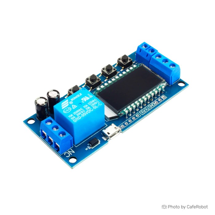
XY-LJ02 Timer Relay Module
$3.2500
In stock
SKU
misc-03-015
Volume discounts:
- +25 4 % $3.1100
- +100 6 % $3.0500
- +300 8 % $2.9800
- +500 10 % $2.9100
- +1000 13 % $2.8400
Ships in 2-3 business days, then:
Free delivery in 12-15 days by Tracked Economic Shipping on orders over $100.
Free delivery in 7-10 days by Express Shipping on orders over $300.
More shipping info

Shop with confidence Learn More
 XY-WJ01 One Way Relay Module Delay Cycle Timing Switch Previous
XY-LJ02 Timer Relay Module Review
The XY-LJ02 Timer Relay Module combines programmable timing control, adjustable delay time, onboard button adjustment, a display, and a relay switching output on a single circuit board. It runs from DC 6V–30V terminal power or a 5V Micro USB input, providing a local timer switch for bench setups, machinery delays, and cycling tasks without microcontroller code or external logic boards.
This module suits low-voltage DIY timing tasks where local push-button setup is preferable to software programming. Its relay switching output is a mechanical switch for an external circuit, not a regulated power supply. For installations requiring formal industrial safety certification, sealed enclosures, verified inductive-load ratings, or network-synchronized scheduling, choose a more documented or enclosed industrial control solution.
Specifications of XY-LJ02 Timer Relay Module
- Operating Voltage: DC 6V-30V or 5V Micro USB
- Average Current: <50mA (standby)
- Relay Output: Can switch up to 10A at 250V AC or 10A at 30V DC
- Timing Range: 0.1 seconds to 999 minutes, adjustable via onboard buttons
- Display: LED display for easy timing setup and monitoring
- Output Signals: Relay switching
- Operating Temperature: -20°C to 70°C
- Dimensions: 80x38.3mm
- Applications: Ideal for automated lighting, motor control, DIY projects, and other timing-based control applications
For standalone automation projects, this unit sits within our broader range of Date & Time Modules for bench automation, timed switching, and project control.
XY-LJ02 Timer Relay Module Specifications Explained
Assess an embedded timer module by considering how its power rails, output contacts, and display work together on the bench. The table below shows how each published specification affects hardware selection and system wiring.
| Specification | Stated Value | Practical Consequence |
|---|---|---|
| Operating Voltage | DC 6V-30V or 5V Micro USB | DC 6V–30V terminal power supports common 12V and 24V control supplies, while 5V Micro USB provides a separate 5V bench power option. |
| Average Current | <50mA (standby) | Represents baseline control-board consumption while waiting; overall draw increases during active relay coil energization. |
| Relay Output | Up to 10A at 250V AC or 10A at 30V DC | Switches a separate external circuit. These printed headline maximums apply strictly to resistive loads; inductive or inrush loads require significant derating. |
| Timing Range | 0.1 seconds to 999 minutes | Covers sub-second pulses through multi-hour delays using button adjustments. Check exact duration requirements before finalizing the build, as generic manuals often describe wider intervals. |
| Display | LED display | Allows parameter entry and interval countdown directly on the board without a computer, mobile app, or serial terminal. |
| Operating Temperature | -20°C to 70°C | Covers standard indoor ambient installations and ventilated enclosures, but excludes harsh outdoor or freezing industrial field deployments. |
| Dimensions | 80x38.3mm | Provides the length and width for panel or enclosure cutouts; total board height and mounting-hole positions must be confirmed directly on the physical board. |
For projects powered from a wall outlet, a dedicated Switching Power Supply SMPS -12V. 2A paired with the screw terminals provides a stable supply within the 6V–30V window. For systems that need voltage-threshold monitoring to trigger timing events, the XY-J05 Timer Relay with Voltage Detection adds integrated upper- and lower-limit voltage measurement. To sequence two loads independently, use the Adjustable Delay Timer Dual Relay with LED Display, which offers dual relay channels with extended function sets. For a basic power-on delay under ten seconds on a 12V rail, the NE555 12V Delay Timer Relay Module provides a simpler analog hardware timer.
XY-LJ02 Timer Relay Modes and Trigger Compatibility
A delay relay must provide the switching logic your sequence needs, whether that is a single delayed shutoff, repeating cycle, or edge-triggered pulse. The XY-LJ02 provides programmable timing control and onboard-button adjustment. Common documentation for the XY-LJ02 family describes P1 through P7 operating programs for triggered one-shot intervals, retriggerable pulses, cyclic execution, power-on continuous looping, and signal-hold states.
These operating modes frequently use three core parameters:
- OP (Open/On time): The duration that the relay contacts remain energized.
- CL (Close/Off time): The duration that the relay contacts remain de-energized during a cycle.
- LOP (Loop count): The number of repeating cycles to execute before halting, or continuous execution if set to infinite.
Selecting the wrong program mode can look like a hardware failure. In retrigger-enabled modes, a new trigger pulse sent while OP is running resets the countdown; in non-retrigger modes, identical pulses are ignored until the cycle finishes. Firmware menus and terminal designations can vary across generic manufacturing runs, so test the specific menu structure of your board on the bench before final installation.
Trigger compatibility depends on the electrical signal. Documentation for the XY-LJ02 family identifies high-level 3V–24V triggering, low-level 0V–0.2V triggering, and passive dry-contact switch inputs. A standard momentary pushbutton wired between the trigger terminals provides reliable manual actuation. Before connecting microcontrollers such as an Arduino, ESP32, or Raspberry Pi, or industrial PLC outputs, verify the shared ground reference, logic voltage levels, and whether the input uses active-high or active-low signaling. A Breadboard Jumper Wire Kit - 140 Pieces is practical for breadboard trigger tests and signal probing.
For projects that benefit from direct dial adjustment instead of digital menus, the Relay Module with Potentiometer Delay uses analog potentiometers to configure on and off times. Where electrical noise or contact bounce causes false activations on sensitive sensor lines, the 5V-30V Trigger Delay Relay Module includes a dedicated hardware pull-up trigger filter.
XY-LJ02 Timer Relay Module Wiring, Load Limits, and Safety
The relay output terminals function strictly as mechanical switch contacts—common, normally open, and normally closed—and do not output voltage. The controlled device needs its own separate power source wired in series through the relay contacts. Treating these terminals as a regulated power output will stop the circuit from operating and can damage connected components.
The module lists a headline rating of up to 10A at 250V AC or 10A at 30V DC, but widely circulated family manuals state 5A at 220V AC and 5A at 30V DC. Do not switch high-draw inductive loads—such as AC compressors, large water pumps, industrial solenoids, or heavy power tools—directly through this board based on the 10A rating alone. Inductive loads produce heavy inrush currents and inductive kickback that can rapidly pit relay contacts or weld them shut. For high-power or inductive applications, use this board to switch a pilot signal to an appropriately rated external contactor, solid-state relay, or intermediate interface relay equipped with snubber or flyback protection.
For a test bench, use a Switching Power Supply SMPS -12V. 2A with the board's DC 6V–30V input terminal block, and reserve a Breadboard Jumper Wire Kit - 140 Pieces for low-voltage signal testing. Power the board through either the terminal block or the 5V Micro USB connector; using both power sources concurrently is unsupported.
For high-current DC loads such as DC blowers, LED arrays, or heating strips, the DC 12-24V Dual MOS Time Delay Cycle Timer Module uses dual MOSFET switching rated up to 15A and 400W, eliminating mechanical contact wear. For enclosed installations, the XY-WJ01 One Way Relay Module Delay Cycle Timing Switch provides a neat panel-mount form factor with an integrated LCD bezel, a 5A relay rating, and an auxiliary UART interface.
XY-LJ02 vs XY-J02 Timer Relay Modules
The XY-LJ02 and generic XY-J02 timer relay module have similar names, perform comparable single-channel delay tasks, and use similar program terminology. They are built on distinct PCB layouts, however, and their physical specifications are not interchangeable.
Physical size is the main distinction: documentation for the XY-J02 reports an approximate footprint of 62 x 38 x 17 mm, while the XY-LJ02 measures 80 x 38.3 mm. Screw-terminal pinouts, button assignments, and internal menu sequences vary across revisions. Do not use XY-J02 documentation to infer terminal functions, trigger polarities, or relay ratings for an XY-LJ02 board. Inspect the silkscreen labels directly on your board before applying power.
Neither family has a real-time calendar clock; both run strictly on elapsed countdown intervals. If your automation depends on wall-clock scheduling—such as turning on a fan every day at 08:00—an elapsed timer will drift over time. For time-of-day operation, the 5-60V Real Time Delay Timer Relay Module with LED Display includes real-time clock synchronization and multiple independent daily scheduling periods. For an intelligent controller built around an Arduino or Raspberry Pi, the DS3231 High-Precision I2C RTC Module provides battery-backed, temperature-compensated timekeeping over an I2C bus.
XY-LJ02 Timer Relay Module Setup and First Test
Bench-test the board with low-voltage signals before installing it in a final wiring enclosure. No computer drivers, development environments, or programming software are required.
- Verify the board: Check that the silkscreen confirms the XY-LJ02 model number, then identify the terminal labels for power, trigger input, and relay contacts.
- Supply power: Connect a regulated DC power source between 6V and 30V to the power screw terminals—such as a Switching Power Supply SMPS -12V. 2A—or plug a 5V supply into the Micro USB port. Verify that the LED display illuminates.
- Configure parameters: Use the onboard pushbuttons to navigate the menu. Select the required operating mode, such as a timed delay on trigger, set the
OPtime duration, and setCLorLOPwhen running a repeating cycle. - Attach test equipment: Connect a digital multimeter set to continuity mode, or wire a small low-voltage LED and battery circuit through the normally open (NO) and common (COM) relay contacts using jumper wires from a Breadboard Jumper Wire Kit - 140 Pieces.
- Test switching and retriggering: Apply a trigger signal or press the trigger switch. Confirm that the display counts down, the relay clicks audibly, and the meter or indicator shows contact closure. Pulse the trigger during countdown to check whether it restarts or pauses the cycle, confirming that the active mode matches your expectations.
- Wire final load: Once functional behavior is verified, remove bench power and wire the final load, confirming proper isolation, line fusing, and load supply paths.
If an external trigger does not start the timer, check whether the board's trigger port is configured for active-high or active-low signaling and confirm that signal ground is properly referenced. If timing durations appear incorrect, check whether the decimal point position on the display is set to tenths of seconds, whole seconds, or minutes.
XY-LJ02 Timer Relay Module FAQ and Buying Checklist
Is this the 5A or 10A version of the XY-LJ02 timer relay?
The product specification lists relay switching up to 10A at 250V AC or 10A at 30V DC. Widespread generic documentation for the XY-LJ02 family instead states a maximum rating of 5A at 220V AC or 5A at 30V DC. Verify the printed markings on the physical relay cube on your board, treat the 10A rating as a resistive-load maximum, and use an external contactor or intermediate power relay when controlling motors, pumps, or mains-voltage equipment.
Can I power the XY-LJ02 Timer Relay Module from USB?
Yes. The module accepts 5V power through its onboard Micro USB connector as an alternative to the DC 6V–30V screw terminals. Use either the terminal block or the Micro USB port, but do not connect power to both inputs simultaneously.
Does the Micro USB port let me program the XY-LJ02 from a computer?
No. The Micro USB port provides 5V electrical power only. It has no USB data transceiver lines, and the module does not support PC configuration software, serial commands, or firmware updates over USB. All adjustments are made directly with the onboard buttons and display.
Does the XY-LJ02 relay output provide 5V, 12V, or 24V to my load?
No. The relay terminals are unpowered dry contacts. They work like a mechanical wall switch in series with your circuit. You must provide an external power source wired in loop with the load and relay contacts.
Can I use an Arduino, ESP32, Raspberry Pi, sensor, or pushbutton to trigger the XY-LJ02?
Yes, but verify electrical compatibility first. A standard mechanical pushbutton wired across the trigger inputs functions reliably. When triggering from a 3.3V or 5V GPIO pin on an Arduino, ESP32, or Raspberry Pi, confirm that the ground reference is shared and that the module's trigger input threshold registers your logic level correctly.
What are P1–P7 on an XY-LJ02 timer relay module?
P1 through P7 refer to firmware operating programs commonly found in XY-LJ02 modules. These programs determine how the relay responds to trigger events, including one-shot delays, retriggerable timers, signal-hold functions, and repeating on/off cycle loops. Because menu structures can vary across production batches, confirm program actions on the bench before committing to a final installation.
Can the XY-LJ02 Timer Relay Module run an automatic on/off cycle?
Yes. The module supports cycle timing that alternates between an energized interval (OP) and a de-energized interval (CL). These cycles can run continuously upon power-up or execute for a pre-programmed loop count (LOP) following a trigger signal.
Is XY-J02 the same as XY-LJ02?
No. Both are single-channel timer relays with similar programming logic, but the XY-LJ02 has a larger PCB footprint (80 x 38.3 mm compared to approximately 62 x 38 x 17 mm for the XY-J02) and differs in terminal arrangement and board layout. Manuals and pin assignments should not be interchanged.
Accessories Overview
- Required: A DC 6V–30V power supply or 5V Micro USB power adapter, such as a Switching Power Supply SMPS -12V. 2A; low-voltage hookup wire such as the Breadboard Jumper Wire Kit - 140 Pieces for bench prototyping; and a separate power supply sized for the load.
- Recommended: A momentary trigger pushbutton, an insulated project enclosure, in-line load circuit fuses, and a dedicated contactor or snubber diode for inductive loads.
- Optional: A Micro USB cable and 5V USB adapter when terminal-block power is unavailable.
Purchase Decision Summary
- Ideal for: DIY makers, hobbyists, and test technicians building low-voltage automation, delayed power-down sequences, or repeating bench cycles configured directly with hardware buttons.
- Maybe for: Sensor- or microcontroller-triggered switching, provided logic thresholds, terminal assignments, and ground paths are checked during bench testing.
- Consider another option if: You need Wi-Fi or PC connectivity, true calendar/time-of-day scheduling, direct heavy-duty AC motor switching, or certified safety-critical control hardware. For low-current logic-level embedded timing without a mechanical relay, look into the Multifunction Delay Trigger Timing Chip. If your controller needs a persistent calendar clock rather than an elapsed delay timer, consider the DS1307 I2C RTC Module or our broader collection of Date & Time Modules.
Buying Checklist
- [ ] I have an available DC 6V–30V supply or 5V Micro USB source to power the control board.
- [ ] I understand that the relay terminals are unpowered dry contacts requiring a separate power supply for the load.
- [ ] The physical 80x38.3mm board dimensions fit inside my planned project enclosure.
- [ ] My application requires an elapsed countdown or repeating cycle, not time-of-day calendar scheduling.
- [ ] My load is either resistive and within safe operating limits, or I have budgeted for an intermediate contactor to handle high-inrush or inductive currents.
- [ ] I am prepared to configure the board using the onboard buttons and display without relying on PC software or USB data connections.
| Interface Type | UART,USB |
|---|---|
| Operating Voltage (V) | 6V to 30V, 5V (Micro USB) |
| Operating Current (mA) | 15mA (standby), 50mA (working) |
| Operating Temp (°C) | -20°C to 70°C |
| Dimensions (mm) | 80 x 38.3 x 19 mm |
| Mounting Type | Screw holes |
| Device Type | Timer |
| Target Interface | UART |
| Alarm | No |
| Relay Channels | 1 |
| Adjustment | UART configuration,Parameter Setting |
| Timing Range | 0.01 sec to 9999 min |
| Functions | power-off delay,trigger delay,loop timing |
| Output Type | Relay |
Write Your Own Review

Please complete your information below to login.
Sign In
Create New Account