Product added to cart

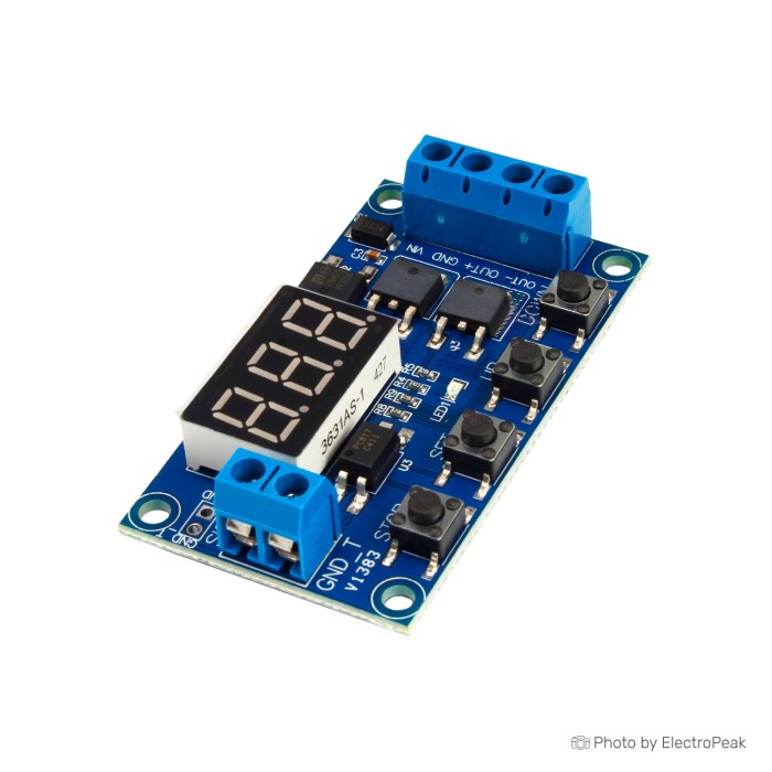
DC 12-24VDual MOS Time Delay Cycle Timer Module
$0.9000
In stock
SKU
MISC-03-011
Volume discounts:
- +100 6 % $0.8500
- +300 8 % $0.8300
- +500 10 % $0.8100
- +1000 11 % $0.8000
Ships in 2-3 business days, then:
Free delivery in10-15 days by YunExpress on orders over $35.
Free delivery in5-7 days by DHL on orders over $200.
More shipping info

Shop with confidence Learn More
 1-Channel Relay Module - 12V Previous
It is a timer relay module with high precision, stable and reliable performance.
Adopt high precision industrial grade chip for accurate timing control.
With strong anti-interfere rejection,
stable performance.
Widely used on timer operating equipment, household electrical appliances, lighting delay modification, factory equipment, time delay control, etc.
Specificatoins of DC 12-24VDual MOS Time Delay Cycle Timer Module:
- Input voltage: 5 to 36 volts
- High excitation signal voltage: 3 to 24 V DC
- Current: 50mA
- Current (idle): 20mA
- Temperature range: -40 to 85
- Size: 60x34.5x12mm
- The time measurement range: 0.1 seconds to 999 minutes
- Power output: 400W (5 to 36 V DC with 15A current at room temperature)
- With signal isolation by optocoupler to prevent noise
- Protection against short circuit and reverse polarity
Usage Notes For DC 12-24VDual MOS Time Delay Cycle Timer Module:
Set timer parameters
¢ To set the system parameters, including working mode and parameters, press the SET key for 3 seconds until the working modes are shown.
¢ Use the UP and DOWN keys to select the desired working mode and then press the SET button momentarily to set other parameters. Set the parameters in the same order.
¢ Finally, after the necessary settings, press the SET button for 3 seconds to configure the desired settings.
To know the value of system or mode parameters set by momentarily pressing the SET key, all parameters will be displayed consecutively.
parameters
OP: relay on time
CL: relay off time
LOP: The number of repetitions of the operation
Modes of operation
P1.1: When the excitation signal is applied, the relay remains connected for OP seconds and then it is disconnected. Applying a re-trigger signal while the output is ON is not valid and will not change the state.
P1.2: By applying any trigger signal, the timer is reset.
P1.3: By applying the stimulation signal, the relay is cut off and the timer is stopped and reset
P2: By applying the excitation signal, the relay is connected with a delay of CL seconds (minutes) and disconnected after OP seconds (minutes).
P3.1: By applying the excitation signal, the relay is connected for OP seconds (minutes) and then disconnected for CL seconds (minutes). This operation is repeated in a loop, the number of repetitions can be adjusted by the LOP parameter.
P3.2: When the system is turned on, the P3.1 mode starts without the need for a trigger signal.
P4: The timer starts with the trigger signal and the relay is connected. The timer will not count until the trigger signal is applied. When the stimulation signal is interrupted and if no new stimulation signal is applied until the end of the OP, the relay is disconnected and waits for the next stimulation signal to connect.
Energy saving modes
Press the Stop key for 2 seconds to select between power saving modes.
C-P mode: After five minutes of the system not being used, the timer display is turned off and the system continues to work normally.
O-d mode: By selecting this option, the system display will continue to work in the always-on mode.
Setting the time range of the timer
XXX 1 to 999 seconds
XX.X 0.1 to 99.9 seconds
X.X.X 1 to 99 minutes
For example, to set a time of 3.2 seconds, it should be "03.2" or "0.0.2" for 2 minutes. value it
Stop function
The main function of this key is to stop the system in an emergency, which has two modes.
ON mode of connecting the relay to perform the included settings
OFF The relay is disconnected and does not respond to the excitation signal
Important Notes
¢ Parameter settings are preserved after the power source is cut off and there is no need to reprogram
¢ Due to the use of MOS technology, the system has a long lifespan and losses are at a minimum, and it also provides high switching power in the output.
¢ To generate the stimulation signal, the positive base of the stimulation signal is connected to a source in the DC voltage range of 3 to 24 volts, and it is enough to connect two earth circuits together to create the stimulation signal.
For the convenience of this case, there is a place on the left side of the board to connect two grounds, which is created by placing a switch and every time the key is pressed, a stimulation signal is created. Creating a high-level trigger by using the common ground of the input and the excitation signal also creates anti-noise properties.
Write Your Own Review

Please complete your information below to login.
Sign In
Create New Account