WSN-03 Wireless Module Features
This module features:
- Transmitting and receiving data over long distances (3.5 to 4 km)
- Operating frequency: 433, 470, 868 and 915 MHz
- Data transfer sensitivity: 120dBmW (decibel-milliwatts)
- Receiving current: less than 30 mA
- Transmitting current: less than 30 mA
- sleep mode current: less than 5 mA
You can download the datasheet of this module here.
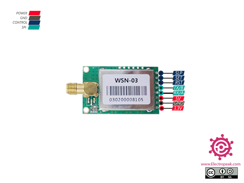
WSN-03 Wireless Module Pinout
This Module has 8 pins:
- 3V: Module power supply – 3.3 V
- GND: Ground
- 5V: Module power supply – 5V
- RX/A: Serial receiver
- TX/B: Serial transmitter
- RST: Reset pin
- SET: Set up pin
- SLP: Sleep mode
You can see the pinout of this module in the image below.
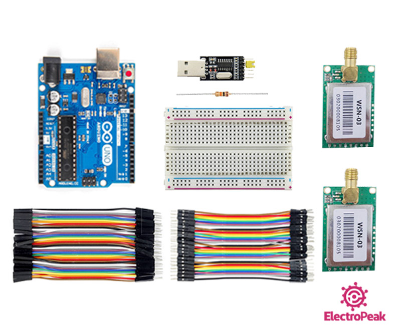
Required Materials
Hardware Components
Software Apps
Interfacing WSN-03 Wireless Module with Arduino
Step 1: Circuit
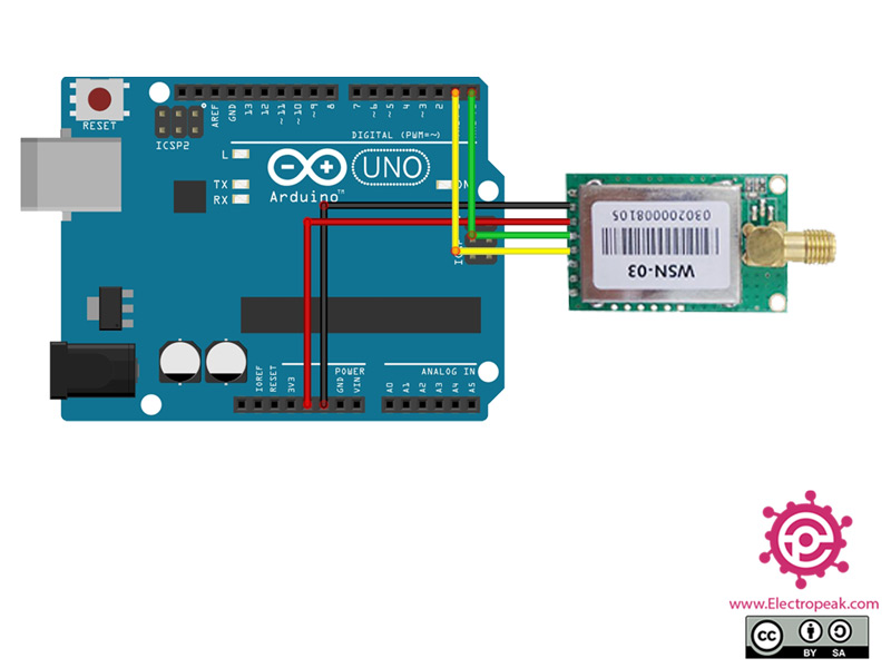
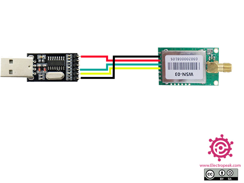
Connect Arduino to the transmitter module and USB to TTL converter to the receiver.
The transmitter circuit connection is as shown below.
The receiver circuit connection is as shown below.
Step 2: Module Setting
Note
This step is done to change the settings and configuration of the module. If your module does not need configuration, you do not need to do this step. These changes include baud rate, parity, number of bits, and so on.
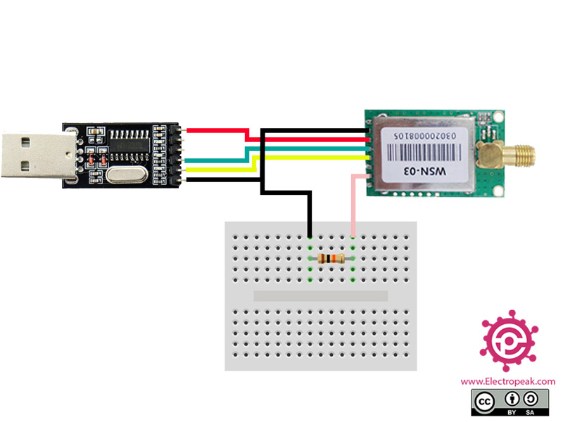
Connect wires accordingly.
Note
You can use bread board to connect the resistor.
Note 1
Note that you must also connect the SET pin to ground using a 10Kohm resistance.
Note 2
In this step, we use the USB to TTL converter and connect the module to it according to the circuit.
You can also use Arduino and connect the Arduino Reset to ground.
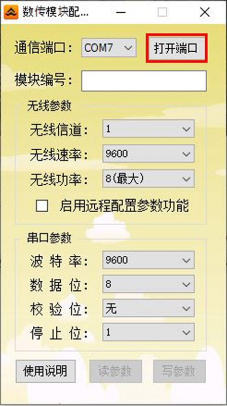
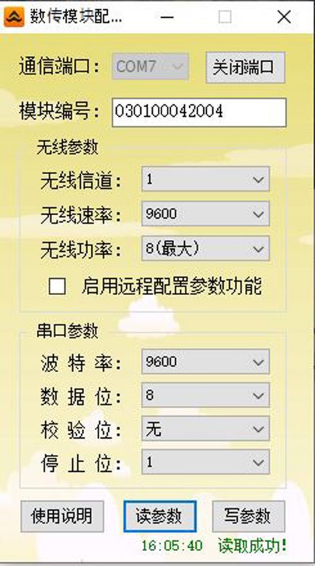
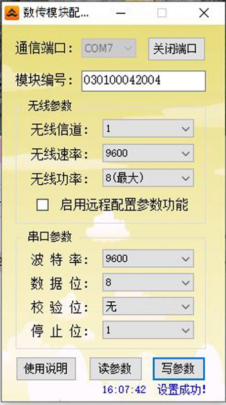
First, run the software. Then enter the data that module must be set up accordingly, and then select the top option which is marked in red. Make sure the module port is selected correctly.
Then select the option marked in green. This will read the module data and its serial (written on the module) will be displayed at the top of the software.
Finally, you must save these changes by selecting the option marked in blue.
Step 3: Interfacing without coding
Connect Arduino to transmitter module and the USB to TTL converter to the receiver module.
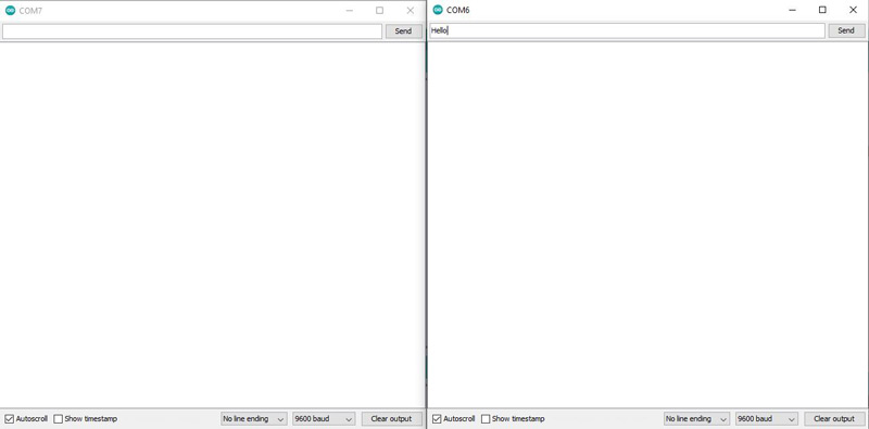
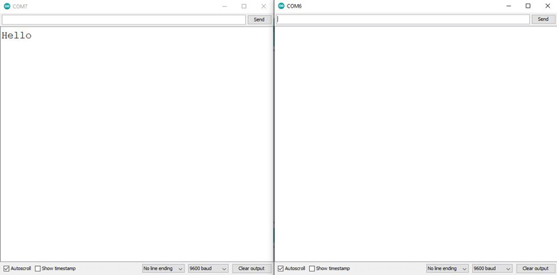
Open two different windows in Arduino. From the tools section, select the converter port and Arduino port. Then open both serial monitors and in the input part of the Arduino monitor serial, write a phrase and send it. It can be seen that the exact same phrase appears on the USB to TTL converter monitor serial.
Look at the following image.
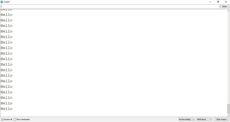
As you can see in the first image, we are sending the phrase “Hello” from Arduino. And in the second image, the desired phrase is sent and displayed in the receiver monitor serial.
Step 4: Interfacing with coding
    /*
  WSN-03-Wireless-Module
  modified on 27 oct 2020
  by Amir Mohammad Shojaee @ Electropeak
  Home

  Based on Arduino Example
*/
#include <SoftwareSerial.h>
SoftwareSerial mySerial(2, 3); // RX, TX

void setup()
{

  Serial.begin(9600);

  // set the data rate for the SoftwareSerial port
  mySerial.begin(9600);

}

void loop() // run over and over
{
  mySerial.println("Hello");
  delay(1000);
}
This code is written for the transmitter. First, with SoftwareSerial, we set pins 2 and 3 into new serial pins for sending data. Next, we want to send the phrase “Hello” to the recipient once every second.
Note
Note that because you selected pins 2 and 3 as the new serial pins, you will need to connect the TX / B pin to Arduino pin 2 and the RX / A pin to Arduino pin 3.
You can see the result in the image below.
