TMC2100 Stepper Motor Driver Features
The TMC2100 driver is one of the most popular stepper motor drivers available on the market. It works similar to the DRV8825 and A4988 drivers.
This module is intended to drive a bipolar stepper motor. Only by using two pins, the rotation direction and rotation steps can be controlled. Each signal sent by the spin step pin, the motor shifts one step. The key features are:
- This driver has 200 steps per revolution in full step (1.8 degrees per step).
- Allowable continuous current per phase: 1.25A (RMS) or 1.77A (max)
- Maximum current in the short term for each phase: 2.5A
- Motor voltage: 5.5 to 46 V
- StealthChop mode to reduce noise
- SpreadCycle mode to increase torque
Note
Note
An onboard potentiometer is used for setting the current limit.
You can download the datasheet of this module here.
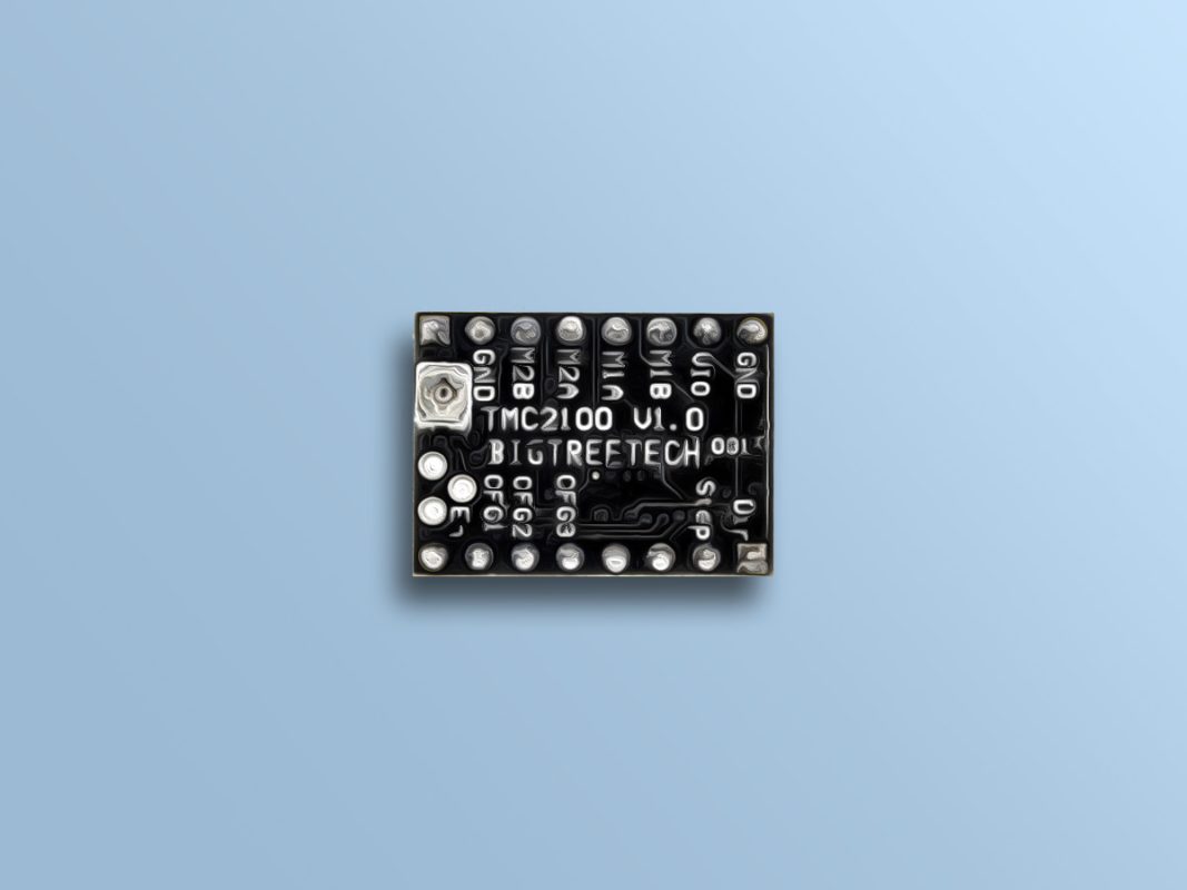
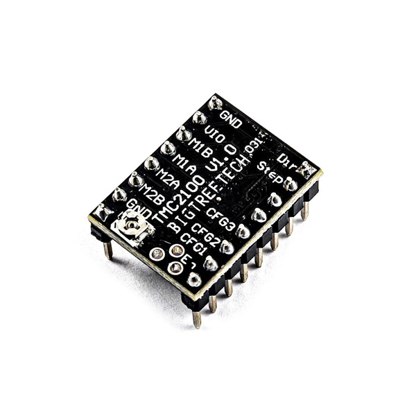
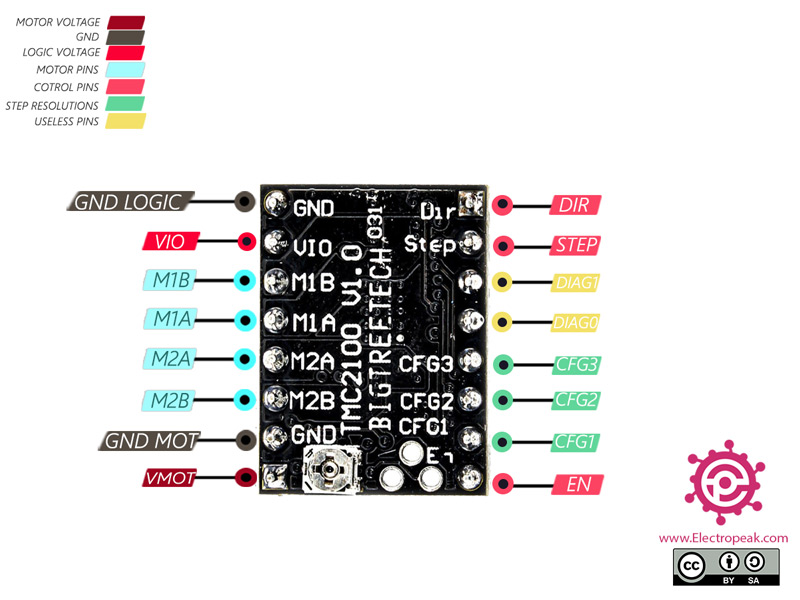
TMC2100 Stepper Motor Driver Pinout
This Module has 8 pins:
Power Supply Pins:
- GND-MOT: Ground Motor power supply
- V-MO: Motor power supply – 5.5 to 46 V
- GND-LOGIC: Ground driver power supply
- V-IO: Input voltage driver power supply
Tip
You can use a capacitor to protect the driver from VMOT voltage sparks.
Motor Coil Pins:
- M1A: Pin 1 for motor coil 1
- M1B: Pin 2 for motor coil 1
- M2A: Pin 1 for motor coil 2
- M2B: Pin 2 for motor coil 2
Pins for controlling power states:
- DIR: Digital signal to control the direction of motor movement
- STEP: Digital signal to control rotation steps
- EN: When this signal is activated, the driver outputs are disabled.
Unused Pins:
- DIAG0: Not used pin
- DIAG1: Not used pin
Driver Setting Pins:
- CFG1: Pin 1 for driver setting
- CFG2: Pin 2 for driver setting
- CFG3: Pin 3 for driver setting
Note
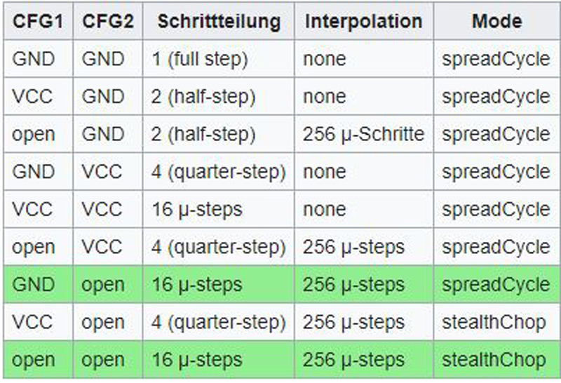
Connect CFG1 to GND for spreadCycle mode.
Various operating modes are provided through connection of the rwo CFG1 and CFG2 pins. Those green highlighted lines are the recommended operating modes:
You can see the pinout of this module in the image below.
Required Materials
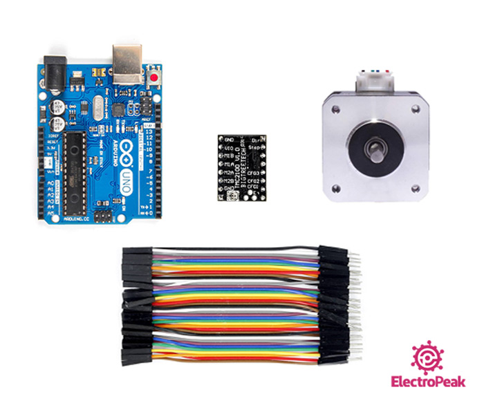
Hardware Components
Software Apps
Note
Be careful, in order to interface this motor by TMC2100 driver, you need a power supply (adapter, battery, etc.) greater than 5.5 V. The power supply is not listed above. Prepare one yourself.
Make sure your power supply is able to supply current for motor coils.
Interfacing TMC2100 Stepper Motor Driver with Arduino
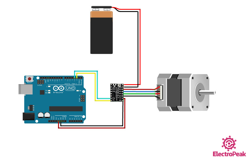
Step 1: Circuit
The following circuit show how you should connect Arduino to TMC2100 module. Connect wires accordingly.
Note
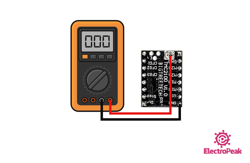
Step 2: Current limit
The best way to regulate motor current is to calculate the Vref using the potentiometer.
First calculate Vref and then IRMS and IMax using the following formulas:
Irms = Vref × 0.71
Imax = Irms × 1.41
Step 3: Code
Upload the following code to your Arduino.
/*
TMC2100 -Stepper-Motor-Driver-Module
made on 2 Dec 2020
by Amir Mohammad Shojaee @ Electropeak
Home
*/
const int dirPin = 2;
const int stepPin = 3;
const int stepsPerRevolution = 3200;
int incomingByte = 0; // for incoming serial data
int input = 0;
void setup() {
pinMode(stepPin, OUTPUT);
pinMode(dirPin, OUTPUT);
Serial.begin(9600); // opens serial port, sets data rate to 9600 bps
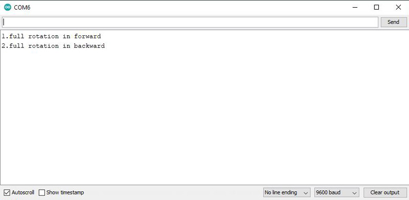
Serial.println("1.full rotation in forward");
Serial.println("2.full rotation in backward");
}
void loop() {
// send data only when you receive data:
if (Serial.available() > 0) {
// read the incoming byte:
incomingByte = Serial.read();
input = incomingByte ;
switch (input) {
case '1': // if input=1 ....... motors turn forward
forward();
break;
case '2': // if input=2 ....... motors turn backward
backward();
break;
}
delay(200);
input=0;
}
}
void forward() { //function of forward
digitalWrite(dirPin, HIGH);
for(int x = 0; x < stepsPerRevolution; x++)
{
digitalWrite(stepPin, HIGH);
delayMicroseconds(100);
digitalWrite(stepPin, LOW);
delayMicroseconds(100);
}
delay(1000); // Wait a second
}
void backward() { //function of backward
digitalWrite(dirPin, LOW);
for(int x = 0; x < stepsPerRevolution; x++)
{
digitalWrite(stepPin, HIGH);
delayMicroseconds(100);
digitalWrite(stepPin, LOW);
delayMicroseconds(100);
}
delay(1000); // Wait a second
}
At the beginning of the program, we determine the DIR and STEP pin numbers. Then we set the driver step to 3200. In this code we have two functions: clockwise and counter-clockwise directions. By pressing number 1, motor rotates clockwise and by pressing number 2, it will rotate counter-clockwise for one round.
Tip
Because the two pins CFG1 and CFG2 are unconnected, the number of engine steps is multiplied by 16. So we store the value 3200 (200 * 16 = 3200) in the stepsPerRevolution variable.
Open the Serial Monitor. By pressing the digit of each option, you can determine the motor movement direction in one turn.