Contents

Interfacing L298N DC Motor Driver Module with Arduino

L298N DC Motor Driver Feature

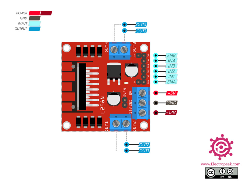
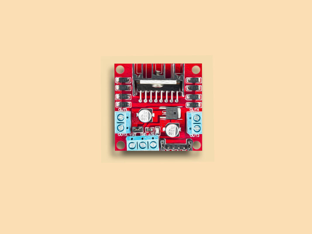
L298N module is used to drive DC motors with a current of less than 2 amps. This module is easy to use. It contains convenient filter circuit and have access to inputs and outputs via pin headers and terminals.

The L298N is a dual full-bridge motor driver that allows two DC motors to be connected simultaneously.

Note

The L298N motor controller follows the H-bridge configuration, so it can be used to drive stepper motors too.

This driver needs a logic voltage supply to drive the motors, which uses a 5-volt regulator to solve the logic voltage supply problem. This module features:

  • Max operating voltage: 46 V DC
  • Max output current: 2 A (Peak 3 A)
  • Power: 25 W
  • Input voltage level: 5 V
  • Working temperature: -25 to 130 Celsius
Note

If the motor is overloaded, the driver temperature will rise rapidly, and since the working temperature of the L298N is between -25 and 130 degrees Celsius, you should cool down the heatsink.

You can download the datasheet of this module here.

L298N Motor Drive Module Pinout

This sensor has 13 pins:

  • +12V: Motor power supply (input)
  • GND: Ground
  • +5V: Module power supply – 5 V (output)
  • ENA: Activator for channel A
  • ENB: Activator for channel B
  • IN1: Input 1 (5 V)
  • IN2: Input 2 (5V)
  • IN3: Input 3 (5V)
  • IN4: Input 4 (5V)
  • OUT1: Output 1
  • OUT2: Output 2
  • OUT3: Output 3
  • OUT4: Output 4

You can see pinout of this module in the image below.

Required Materials

Hardware Components

Arduino UNO R3 × 1
L298N Motor Drive Module × 1
GA12-N20 Gear Motor × 1
Male to Female jumper wire × 1

Software Apps

Arduino IDE

Interfacing L298N Motor Drive Module with Arduino

Step 1: Circuit

The following circuit shows how you should connect Arduino to L298N module. Connect wires accordingly.

Step 2: Code

Upload the following code to your first Arduino.

    /*
  L298N DC MOTOR DRIVER MODULE
  modified on 25 Sep 2020
  by Saeed Olfat @ Electropeak
  
Home
*/ void setup() { pinMode(8, OUTPUT); //IN2 pinMode(9, OUTPUT); //IN1 pinMode(10, OUTPUT); //Enable Pin } void loop() { // Full speed forward digitalWrite(8, HIGH); digitalWrite(9, LOW); digitalWrite(10, HIGH); delay(3000); // Full speed backward digitalWrite(8, LOW); digitalWrite(9, HIGH); digitalWrite(10, HIGH); delay(3000); // 0 to 100% speed in forward mode for (int i=0;i<256;i++) { digitalWrite(8, HIGH); digitalWrite(9, LOW); analogWrite(10, i); delay(20); } delay(50); // 0 to 100% speed in backward mode for (int i=0;i<256;i++) { digitalWrite(8, LOW); digitalWrite(9, HIGH); analogWrite(10, i); delay(20); } delay(50); }

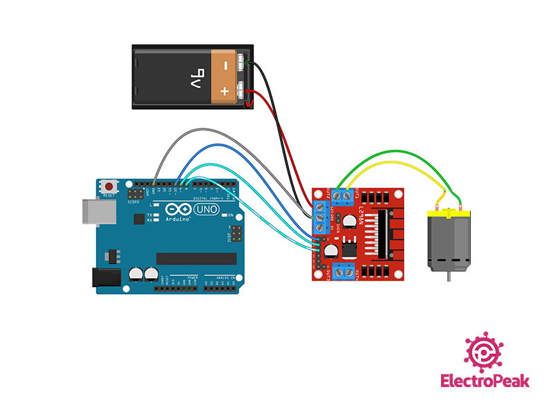
As you can see in the code, the motor first moves forward for 3 seconds and then backward for 3 seconds. Then the motor stops and its speed increases from 0 to 100% in the forward direction with constant acceleration, and then the same is done in reverse direction.

By following these steps, you can successfully interface the L298N DC motor driver module with Arduino, allowing precise control over your motors.

Liked What You See?​
Get Updates And Learn From The Best​

Leave a Reply

Your email address will not be published. Required fields are marked *