Interfacing IRF520 MOSFET Driver Module (HCMODU0083) with Arduino
Written by
Amir Mohammad Shojaei
Discover how to effectively interface the IRF520 MOSFET Driver Module (HCMODU0083) with Arduino in this step-by-step tutorial. Learn about the key features of this module and explore its applications in controlling DC motors using Pulse Width Modulation (PWM) technique. With the ability to convert a constant input voltage to a variable voltage, this module allows precise control over the speed of your DC motor. Whether you’re a beginner or an experienced Arduino enthusiast, this guide will help you master the art of interfacing the IRF520 MOSFET Driver Module.
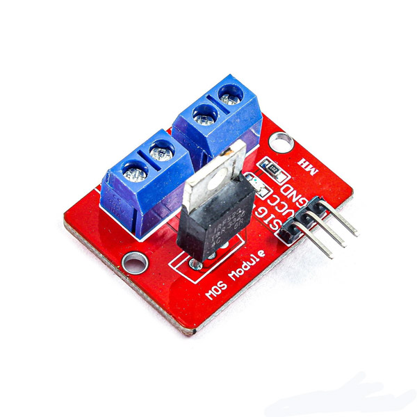
IRF520 MOSFET Driver Module Features
This module controls DC motors by PWM (Pulse Width Modulation) technique. These modules convert a constant input voltage to a variable voltage. DC Motor’s speed can also be controlled by changing the voltage across it. PWMs usually have a constant frequency and can control the engine speed by controlling the length of time that the pulse is HIGH (Duty Cycle). Engine speed control modules are very versatile and easy to use.
Note
DC motor’s voltage can be 0 to 24 volts and the maximum current can be up to 5A. In high currents heatsink is required.
You can download the datasheet of this module here.
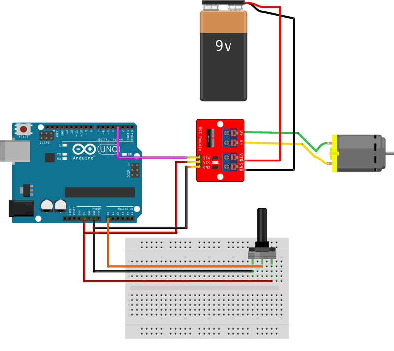
In this code, by rotating the potentiometer, the value of PWM pin 3 changes from 0 to 5. The voltage of the motor also changes from 0 to 9. It can be seen that by turning the potentiometer, the motor speed can be controlled.
Warning
Be careful not to fully turn the pententiometer because the motor is a 6 volts DC motor and the input voltage is 9 volts and the motor may be damaged. Of course, you can use a lower voltage battery or a higher voltage motor.
Unlock the Potential of IRF520 MOSFET Driver Module with Arduino
The IRF520 MOSFET Driver Module combined with Arduino opens up a world of possibilities for motor control applications. By leveraging the power of PWM and the ease of Arduino programming, you can achieve precise and efficient control over your DC motors. Experiment with different voltages, explore advanced motor control techniques, and take your Arduino projects to new heights with the IRF520 MOSFET Driver Module.
Hello Dana,
If you’re using digital mode (non-PWM), the maximum number is determined by the available digital output pins on your microcontroller(any Arduino, ESP or STM). You can also expand the control range by using shift registers.
For PWM mode (speed control), the maximum number is defined by the available PWM pins on your microcontroller or by using a PWM expander.


Comments (4)
can i use node mcu instead of arduino uno with irf540 N mosfet module . If no , can you tell me a better solution for this ?
Hi
yes. you can use it. this module just need a PWM output for control and drive the motor
How many of these could an Arduino turn on at the same time?
Hello Dana,
If you’re using digital mode (non-PWM), the maximum number is determined by the available digital output pins on your microcontroller(any Arduino, ESP or STM). You can also expand the control range by using shift registers.
For PWM mode (speed control), the maximum number is defined by the available PWM pins on your microcontroller or by using a PWM expander.