
Overview
Suppose you want to make a 4x4x4 LED matrix. You will need 64 digital pins to control such an LED matrix. So, it would not be affordable if you decided to choose a microcontroller which has that number of digital pins. So, what is the alternative? In such cases, the most suitable way is to use a shift register to increase the number of digital pins of your microcontroller.
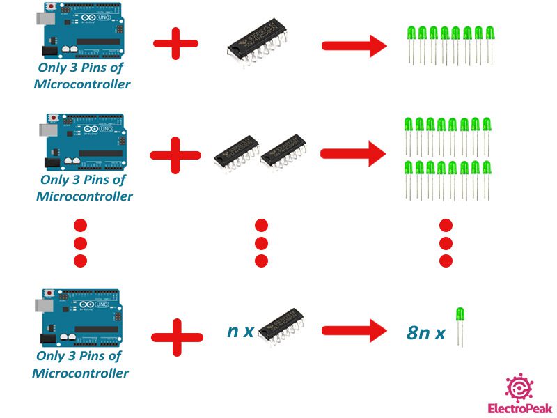
Increasing the number of digital pins of microcontrollers is among the most attractive and practical topics. In many applications, instead of using a more expensive microcontroller, we can increase the number of microcontroller pins by using a shift register such as the 74HC595 IC. One of its most important applications is in projects that use a large number of LEDs. With this tutorial, you can control a lot of LEDs using just a few digital pins of your Arduino.
Sometimes there are so many sensors and modules connected to your microcontroller and you can’t allocate enough pins to use for your LEDs and switches. In that case, it’s best to use a shift register IC to increase the number of microcontroller digital pins.
Here are the goals of this tutorial:
· Increasing the number of microcontroller digital pins
· Cost saving and the ability to use a cheaper microcontroller with fewer number of pins
Using a shift register, 3 microcontroller pins can be increased to 8. While using two shift registers in series, we can increase the pins up to 16.
What You Will Learn
In this tutorial, first we’ll be talking about the 74HC595 shift register IC. Then, with 3 Arduino pins and a shift register, we control 8 LEDs in different modes. We will then use two of these shift registers to control 16 LEDs occupying only 3 pins of Arduino.
We use an Arduino Uno board as our microcontroller and three digital pins of it to control multiple LEDs.
What is the 74HC595 Shift Register?
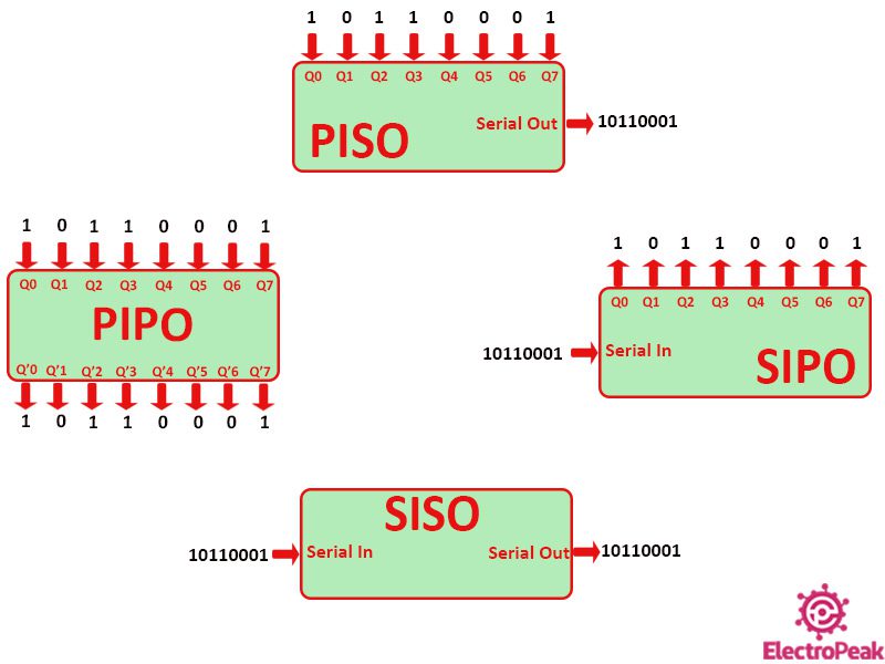
Shift registers are usually used in circuits to transmit or store binary data. These ICs convert serial and parallel data to each other. Based on this description, shift registers are divided into four categories:
- SIPO: Input data is serial and output data is parallel.
The shift registers in this category are commonly used when we want to control some outputs with parallel data.
- PISO: Input data is parallel and output data is serial.
The shift registers of this category are used when we want to convert a number of parallel inputs to serial data.
- PIPO & SISO: The inputs and outputs of these two categories are similar. PIPO has parallel inputs and outputs and SISO has serial inputs and outputs. The shift registers in these two categories act as a buffer and are used to store data at a certain time.
In this tutorial, the microcontroller data is transmitted serially. And we are going to control some LEDs independently. Therefore, we have to use a SIPO shift register. That’s why we have selected the 74HC595 shift register which is in this category.
74HC595 Shift Register IC Pinout
You can see the pinout of the 74HC595 shift register IC in the image below.
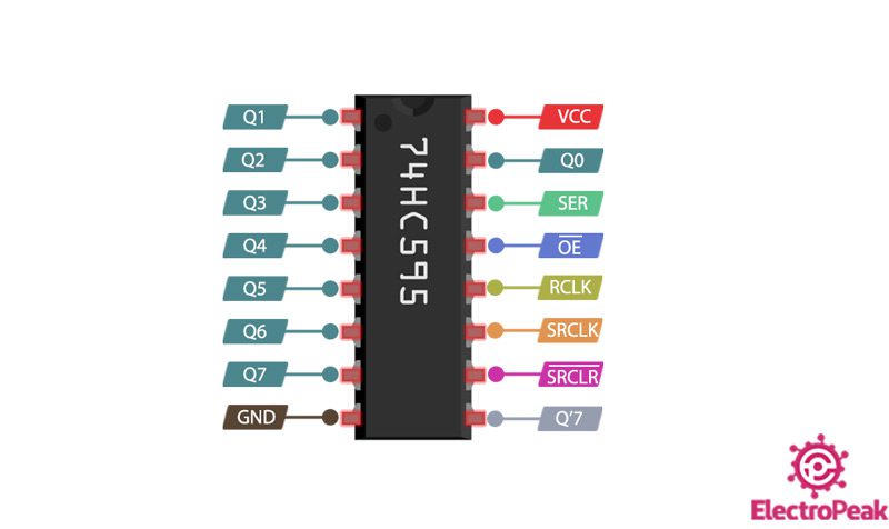
The pins of the 74HC595 IC are as follows:
- GND: Electrical ground
- VCC: Supply voltage – 5 volts
- SER: Serial data pin – Using this pin, data is sent bit by bit to the shift register. The bit 0 of the shift register is connected to this pin.
- SRCLK: Clock pin of the shift register – By each rising edge of the clock, the bits stored in the shift register are shifted one unit.
- RCLK: Clock pin of the latch register – Each time this pin becomes High, the 8 bits stored in the shift register will be placed on the output via the latch register. The output pins of the latch register are connected to the IC outputs (Q0-Q7).
- OE: Output Enable – This pin is active low. Whenever this pin is Low, the outputs are available.
- Q0-Q7: The outputs – The eight outputs of the 74 HC595 IC that can be connected to LEDs or any other devices.
- SRCLR: Clear pin – This pin is active low. Whenever this pin becomes Low, all bits of the shift register will be reset to zero. Normally, this pin is kept High.
- Q7’: Output pin 7 – This pin is used to connect two or more shift registers to each other. The data pin of the Arduino is connected to the SER pin of the first shift register, the Q7’ pin of the first shift register is connected to the SER pin of the second shift register, and so on. This way, 2 or more shift registers can be connected in series and the number of outputs can be increased to 16, 24, …
You can download the 74CH595 datasheet below.
How 74HC595 Shift Register IC Works
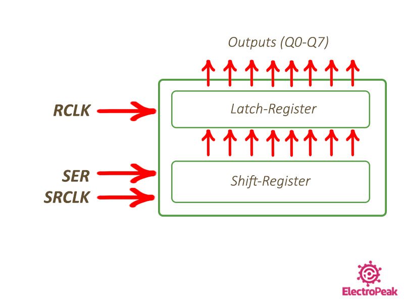
Each 74HC595 shift register IC consists of two registers:
- Shift register: The input data is converted bit by bit from serial to parallel through this register. The SRCLK pin is the clock of this register. With each rising edge of the clock, the data in this shift register is shifted one unit. The SRCLR pin also resets all bits in this register to zero.
- Latch register: The bits are placed on the output pins by this register. The RCLK pin is the clock of this register. Each time this pin becomes HIGH, the bits of data stored in the shift register are placed on the output pins.
Data transfer by the 74hc595 shift register IC generally consists of two steps:
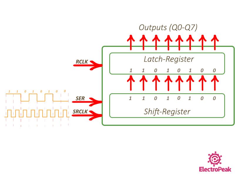
Step 1: Transferring One Byte of Data from Microcontroller to Shift Register
Each byte of data is transferred bit by bit. Thus, the clock must generate one pulse for each bit of data sent. For example, we need 8 clock pulses to transfer 8 bits of data.
For example, suppose we are going to send the binary data 11010100:
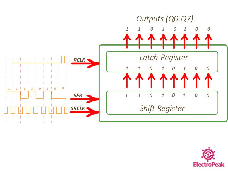
Step 2: Placing Data on Output Pins by Latch Register
Once 8 bits of data are placed on the output of the internal shift register, the clock of the latch register generates a pulse. Then, the transmitted data will be placed on the output pins of the 74HC595 IC.
Required Material
To continue with the tutorial, you need the following components:
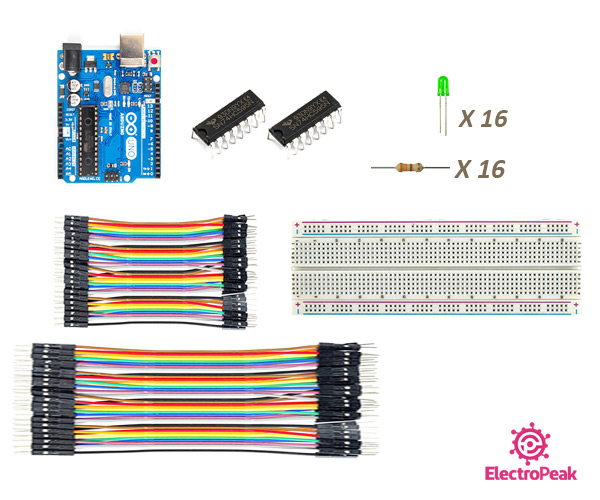
Hardware Components
Software
Increasing Arduino Digital Pins from 3 to 8 Using One 74HC595 Shift Register
With each of the 74HC595 shift register ICs, you can increase 3 Arduino digital pins to 8. We want to control 8 LEDs with 3 Arduino pins. Normally, we would have to use 8 Arduino digital pins to control 8 LEDs. But using this IC, we can control these LEDs with only 3 digital pins of Arduino.
Step 1: Circuit
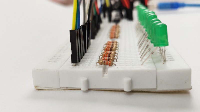
First, we prepare the circuit on the breadboard and make the following connections according to the 74HC595 shift register pinout.
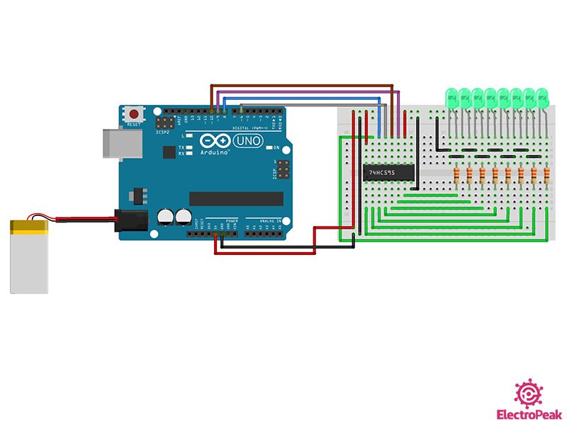
The following points are worth mentioning regarding the circuit above:
- The SRCLR pin which does the resetting is connected to VCC. (So that it doesn’t reset)
- The OE pin is connected to pin 6 of the Arduino to control the brightness of the LEDs.
- The power supply pin of the IC is connected to the Arduino 5V pin.
- 330-ohm resistors are used to reduce the current passing through the LEDs.
In addition, the 4 control pins of the 74HC595 shift register are connected to the Arduino as follows:
- Clock pin of the shift register (SRCLK) to Arduino pin 9
- Serial data pin (SER) to Arduino pin 10
- Clock pin of the latch register (RCLK) to Arduino pin 8
- Output enable pin (OE) to Arduino pin 6
Step 2: Code
Once you have prepared the circuit, connect your Arduino to the computer and upload the following code on it:
/*
 Made on 13 July 2021
 By Amirmohammad Shojaei
 Home
*/

int latchPin = 10; // Latch pin of 74HC595 is connected to Digital pin 10
int clockPin = 9; // Clock pin of 74HC595 is connected to Digital pin 9
int dataPin = 8; // Data pin of 74HC595 is connected to Digital pin 8

int j;
int OE = 6; // Output Enable pin of 74HC595 is connected to Digital pin 8

byte leds = 0; // Variable to hold the pattern of which LEDs are currently turned on or off

void setup()
{
 // Set all the pins of 74HC595 as OUTPUT
 pinMode(latchPin, OUTPUT);
 pinMode(dataPin, OUTPUT);
 pinMode(clockPin, OUTPUT);
 pinMode(OE, OUTPUT);

}

void loop() {
 state_1();
 state_1(); //play state_1 for 3 times
 state_1();
 delay(300);
 state_2();
 state_2(); //play state_2 for 3 times
 state_2();
 delay(300);
 state_3();
 state_3(); //play state_3 for 3 times
 state_3();
 delay(300);
 state_4();
 state_4(); //play state_4 for 3 times
 state_4();
 delay(300);
}

/*
 updateShiftRegister() - This function sets the latchPin to low, then calls the Arduino function 'shiftOut' to shift out contents of variable 'leds' in the shift register before putting the 'latchPin' high again.
*/
void updateShiftRegister()
{
 digitalWrite(latchPin, LOW);
 shiftOut(dataPin, clockPin, MSBFIRST, leds);
 digitalWrite(latchPin, HIGH);
}

/*
 this function is used to control LED light in state_4 function
*/
void brightness(int b) {
 analogWrite(OE, 255 - b);
}

void state_1() {
 brightness(255);
 leds = 0; // Initially turns all the LEDs off, by giving the variable 'leds' the value 0
 updateShiftRegister();
 delay(50);
 for (int i = 0; i < 8; i++)
 {
 bitSet(leds, i); // Set the bit that controls that LED in the variable 'leds'
 updateShiftRegister();
 delay(50);
 leds = 0;
 }
 for (int i = 6; i > -1; i--)
 {
 bitSet(leds, i); // Set the bit that controls that LED in the variable 'leds'
 updateShiftRegister();
 delay(50);
 leds = 0;
 updateShiftRegister();
 }
}


void state_2() {
 brightness(255);
 leds = 0; // Initially turns all the LEDs off, by giving the variable 'leds' the value 0
 updateShiftRegister();
 delay(50);
 for (int i = 0; i < 8; i++)
 {
 bitSet(leds, i); // Set the bit that controls that LED in the variable 'leds'
 updateShiftRegister();
 delay(50);
 }
 for (int i = 7; i > -1; i--)
 {
 bitClear(leds, i);
 updateShiftRegister();
 delay(50);
 }
}

void state_3() {
 brightness(255);
 leds = 0; // Initially turns all the LEDs off, by giving the variable 'leds' the value 0
 updateShiftRegister();
 delay(50);
 for (int i = 0; i < 4; i++)
 {
 j = 7 - i; // 0-7/1-6/2-5/3-4
 bitSet(leds, i); // Set the bit that controls that LED in the variable 'leds'
 bitSet(leds, j);
 updateShiftRegister();
 delay(100);
 }
 for (int i = 0; i < 4; i++)
 {
 j = 7 - i; // 0-7/1-6/2-5/3-4
 bitClear(leds, i); // Set the bit that controls that LED in the variable 'leds'
 bitClear(leds, j);
 updateShiftRegister();
 delay(100);
 }
}

void state_4() {
 brightness(255);
 leds = 0b11111111;
 updateShiftRegister();
 for (byte y = 255; y > 0; y--)
 {
 brightness(y);
 delay(5);
 }
 for (byte z = 0; z < 255; z++)
 {
 brightness(z);
 delay(5);
 }
 leds = 0;
 updateShiftRegister();
}
Eight LEDs are controlled by a 74HC595 IC using the code above. We have considered 4 modes for LED brightness, which are run three times in the main loop, one after another.
We have used the updateshiftregister() function to place the data on the output of the 74HC595 IC. In this function, the shiftOut() command is used to transfer the serial data from the Arduino to the 74HC595 shift register.
Here are a few tips about the shiftOut() command:
- The pin number of the shift register’s clock and the serial data must be entered.
- The third parameter indicates whether the serial data transmission is from LSB (Least Significant Bit) or MSB (Most Significant Bit).
- The last parameter is the serial data to be sent.
A function called brightness() is also defined to adjust the brightness of LEDs:
- By changing the OE pin from 0 to 255, the brightness of the LEDs can be adjusted.
- Since the OE pin is Active Low, its value must be set to 0 for maximum brightness.
- Note that we need to connect the OE pin to one of the Arduino PWM pins.
Each of the 4 states below is defined in a separate function, which we will explain below.
State_1
In this case, only one of the LEDs lights up at a time. The LEDs will light up one after another from right to left, then from left to right. Its code is as follows:
void state_1() {
 brightness(255);
 leds = 0; // Initially turns all the LEDs off, by giving the variable 'leds' the value 0
 updateShiftRegister();
 delay(50);
 for (int i = 0; i < 8; i++)
 {
 bitSet(leds, i); // Set the bit that controls that LED in the variable 'leds'
 updateShiftRegister();
 delay(50);
 leds = 0;
 }
 for (int i = 6; i > -1; i--)
 {
 bitSet(leds, i); // Set the bit that controls that LED in the variable 'leds'
 updateShiftRegister();
 delay(50);
 leds = 0;
 updateShiftRegister();
 }
}
First, we set the brightness to maximum. Before starting the main loop, we set the serial data variable (leds) to zero and set it to the output by the updateshiftregister() function. In the first “for” loop, we set the serial bits to 1 in order from right to left. This is done by the bitSet() command. When finished, we repeat the same process from left to right. The status of the LEDs, in this case, is as follows:
State_2
In the second case, the LEDs light up from right to left, and as the next LEDs light up, the previous LEDs also stay on. When completed, all LEDs are on. Then, the LEDs start turning off from the left in the same way. The code of this case is as follows:
void state_2() {
 brightness(255);
 leds = 0; // Initially turns all the LEDs off, by giving the variable 'leds' the value 0
 updateShiftRegister();
 delay(50);
 for (int i = 0; i < 8; i++)
 {
 bitSet(leds, i); // Set the bit that controls that LED in the variable 'leds'
 updateShiftRegister();
 delay(50);
 }
 for (int i = 7; i > -1; i--)
 {
 bitClear(leds, i);
 updateShiftRegister();
 delay(50);
 }
}
First, we set the brightness to maximum. Before starting the main loop, we set the serial data variable (leds) to zero and set it to the output by the updateshiftregister() function. In the first “for” loop, as in the previous case with the bitSet() command, we set the bits of the “leds” variable to one in order from LSB to MSB. The difference with the first case is that we do not set all bits to zero in each step. In the second “for” loop, we start to turn off the LEDs with the bitClear() command from the left. The status of the LEDs changes as in the clip below.
State_3
In this mode, LEDs 0 & 7, 1 & 6, 2 & 5, and 3 & 4 light up simultaneously. The code for this mode is as follows.
void state_3() {
 brightness(255);
 leds = 0; // Initially turns all the LEDs off, by giving the variable 'leds' the value 0
 updateShiftRegister();
 delay(50);
 for (int i = 0; i < 4; i++)
 {
 j = 7 - i; // 0-7/1-6/2-5/3-4
 bitSet(leds, i); // Set the bit that controls that LED in the variable 'leds'
 bitSet(leds, j);
 updateShiftRegister();
 delay(100);
 }
 for (int i = 0; i < 4; i++)
 {
 j = 7 - i; // 0-7/1-6/2-5/3-4
 bitClear(leds, i); // Set the bit that controls that LED in the variable 'leds'
 bitClear(leds, j);
 updateShiftRegister();
 delay(100);
 }
}
First, like in the previous stages, we set the brightness to maximum. Before starting the main loop, we set the serial data variable (leds) to zero and set it to the output by the updateshiftregister() function. In the following, we define two variables, i and j, and then create our desired design with them.
State_4
In the last mode, we are going to control the brightness of the LEDs.
void state_4() {
 brightness(255);
 leds = 0b11111111;
 updateShiftRegister();
 for (byte y = 255; y > 0; y--)
 {
 brightness(y);
 delay(5);
 }
 for (byte z = 0; z < 255; z++)
 {
 brightness(z);
 delay(5);
 }
 leds = 0;
 updateShiftRegister();
}
In this case, we first turn on the LEDs using the binary value 0b11111111. Then, in the first “for” loop, the brightness of the LEDs is gradually reduced to zero using the brightness function. In the second loop, the opposite is done and the brightness of the LEDs is increased gradually. The clip below shows how the status of the LEDs changes.
Step 3: Display the Results
4 different modes of LEDs were explained separately. Now the final step is to run all 4 previous modes in a row. The final output is as follows.
Increasing the Arduino Digital Pins from 3 to 16 Using Two 74HC595 Shift Registers
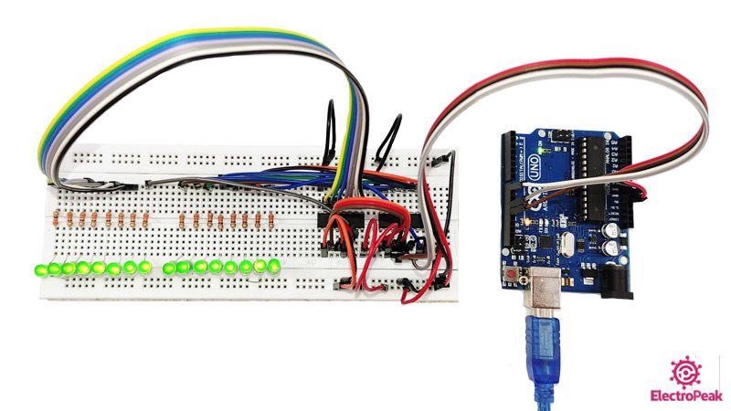
Now in this part, we want to control 16 LEDs independently using two 74HC595 shift registers connected in series. To do this, we use 3 Arduino pins.
Step 1: Circuit
First, we prepare the circuit according to the image below.
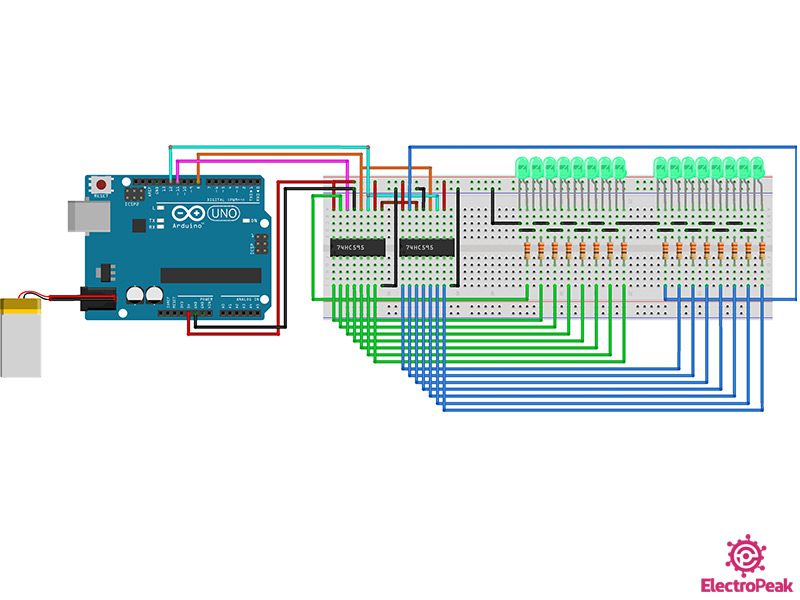
In this part, we are going to control 16 LEDs independently using two 74HC595 shift registers. All 8 LEDs are connected to the 74HC595 IC.
Here are a few notes about controlling two 74HC595 shift registers simultaneously:
- Clock pins of the shift register (SRCLK) and clock pins of the latch register (RCLK) are shared between two 74HC595 ICs. The SRCLK is controlled by pin 12 of the Arduino and the RCLK is controlled by pin 8 of the Arduino.
- The Arduino pin 11 is connected to the serial data pin –SER- of the first 74HC595 shift register.
- The serial data of the second shift register is provided by the series connection with the first shift register. Thus, to establish a series connection between the two shift registers, we connect the Q7’ pin of the first shift register to the serial pin –SER- of the second shift register.
- Connect the SRCLR pin to VCC and OE pin to GND.
- 8 LEDs are connected to each of the 74HC595 shift registers.
- 330 Ohm resistors are used to limit the current of the LEDs.
Step 2: Code
After completing the above circuit, upload the following code on your Arduino.
/*
Modified on 13 July 2021
By Amirmohammad Shojaei
Home
based on www.Arduino.cc Example
*/
//Pin connected to ST_CP of 74HC595
int latchPin = 8;
//Pin connected to SH_CP of 74HC595
int clockPin = 12;
//Pin connected to DS of 74HC595
int dataPin = 11;
//holders for infromation you're going to pass to shifting function
byte dataRED;
byte dataGREEN;
byte dataArrayRED[33];
byte dataArrayGREEN[33];
void setup() {
//set pins to output because they are addressed in the main loop
pinMode(latchPin, OUTPUT);
Serial.begin(9600);
//Arduino doesn't seem to have a way to write binary straight into the code
//so these values are in HEX. Decimal would have been fine, too.
dataArrayRED[0] = 0b11111111;
dataArrayRED[1] = 0b11111110;
dataArrayRED[2] = 0b11111100;
dataArrayRED[3] = 0b11111000;
dataArrayRED[4] = 0b11110000;
dataArrayRED[5] = 0b11100000;
dataArrayRED[6] = 0b11000000;
dataArrayRED[7] = 0b10000000;
dataArrayRED[8] = 0b00000000;
dataArrayRED[9] = 0b00000000;
dataArrayRED[10] = 0b00000000;
dataArrayRED[11] = 0b00000000;
dataArrayRED[12] = 0b00000000;
dataArrayRED[13] = 0b00000000;
dataArrayRED[14] = 0b00000000;
dataArrayRED[15] = 0b00000000;
dataArrayRED[16] = 0b00000000;
dataArrayRED[17] = 0b00000000;
dataArrayRED[18] = 0b00000000;
dataArrayRED[19] = 0b00000000;
dataArrayRED[20] = 0b00000000;
dataArrayRED[21] = 0b00000000;
dataArrayRED[22] = 0b00000000;
dataArrayRED[23] = 0b00000000;
dataArrayRED[24] = 0b00000000;
dataArrayRED[25] = 0b00000000;
dataArrayRED[26] = 0b10000000;
dataArrayRED[27] = 0b11000000;
dataArrayRED[28] = 0b11100000;
dataArrayRED[29] = 0b11110000;
dataArrayRED[30] = 0b11111000;
dataArrayRED[31] = 0b11111100;
dataArrayRED[32] = 0b11111110;
dataArrayRED[33] = 0b11111111;
//Arduino doesn't seem to have a way to write binary straight into the code
//so these values are in HEX. Decimal would have been fine, too.
dataArrayGREEN[0] = 0b11111111;
dataArrayGREEN[1] = 0b11111111;
dataArrayGREEN[2] = 0b11111111;
dataArrayGREEN[3] = 0b11111111;
dataArrayGREEN[4] = 0b11111111;
dataArrayGREEN[5] = 0b11111111;
dataArrayGREEN[6] = 0b11111111;
dataArrayGREEN[7] = 0b11111111;
dataArrayGREEN[8] = 0b11111111;
dataArrayGREEN[9] = 0b11111110;
dataArrayGREEN[10] = 0b11111100;
dataArrayGREEN[11] = 0b11111000;
dataArrayGREEN[12] = 0b11110000;
dataArrayGREEN[13] = 0b11100000;
dataArrayGREEN[14] = 0b11000000;
dataArrayGREEN[15] = 0b10000000;
dataArrayGREEN[16] = 0b00000000;
dataArrayGREEN[17] = 0b10000000;
dataArrayGREEN[18] = 0b11000000;
dataArrayGREEN[19] = 0b11100000;
dataArrayGREEN[20] = 0b11110000;
dataArrayGREEN[21] = 0b11111000;
dataArrayGREEN[22] = 0b11111100;
dataArrayGREEN[23] = 0b11111110;
dataArrayGREEN[24] = 0b11111111;
dataArrayGREEN[25] = 0b11111111;
dataArrayGREEN[26] = 0b11111111;
dataArrayGREEN[27] = 0b11111111;
dataArrayGREEN[28] = 0b11111111;
dataArrayGREEN[29] = 0b11111111;
dataArrayGREEN[30] = 0b11111111;
dataArrayGREEN[31] = 0b11111111;
dataArrayGREEN[32] = 0b11111111;
dataArrayGREEN[33] = 0b11111111;
//function that blinks all the LEDs
//gets passed the number of blinks and the pause time
blinkAll_2Bytes(2, 500);
}
void loop() {
for (int j = 0; j < 34; j++) {
//load the light sequence you want from array
dataRED = dataArrayRED[j];
dataGREEN = dataArrayGREEN[j];
//ground latchPin and hold low for as long as you are transmitting
digitalWrite(latchPin, 0);
//move 'em out
shiftOut(dataPin, clockPin, dataGREEN);
shiftOut(dataPin, clockPin, dataRED);
//return the latch pin high to signal chip that it
//no longer needs to listen for information
digitalWrite(latchPin, 1);
delay(30);
}
}
// the heart of the program
void shiftOut(int myDataPin, int myClockPin, byte myDataOut) {
// This shifts 8 bits out MSB first,
//on the rising edge of the clock,
//clock idles low
//internal function setup
int i = 0;
int pinState;
pinMode(myClockPin, OUTPUT);
pinMode(myDataPin, OUTPUT);
//clear everything out just in case to
//prepare shift register for bit shifting
digitalWrite(myDataPin, 0);
digitalWrite(myClockPin, 0);
//for each bit in the byte myDataOut�
//NOTICE THAT WE ARE COUNTING DOWN in our for loop
//This means that %00000001 or "1" will go through such
//that it will be pin Q0 that lights.
for (i = 7; i >= 0; i--) {
digitalWrite(myClockPin, 0);
//if the value passed to myDataOut and a bitmask result
// true then... so if we are at i=6 and our value is
// %11010100 it would the code compares it to %01000000
// and proceeds to set pinState to 1.
if ( myDataOut & (1 << i) ) {
pinState = 1;
}
else {
pinState = 0;
}
//Sets the pin to HIGH or LOW depending on pinState
digitalWrite(myDataPin, pinState);
//register shifts bits on upstroke of clock pin
digitalWrite(myClockPin, 1);
//zero the data pin after shift to prevent bleed through
digitalWrite(myDataPin, 0);
}
//stop shifting
digitalWrite(myClockPin, 0);
}
//blinks the whole register based on the number of times you want to
//blink "n" and the pause between them "d"
//starts with a moment of darkness to make sure the first blink
//has its full visual effect.
void blinkAll_2Bytes(int n, int d) {
digitalWrite(latchPin, 0);
shiftOut(dataPin, clockPin, 0);
shiftOut(dataPin, clockPin, 0);
digitalWrite(latchPin, 1);
delay(200);
for (int x = 0; x < n; x++) {
digitalWrite(latchPin, 0);
shiftOut(dataPin, clockPin, 255);
shiftOut(dataPin, clockPin, 255);
digitalWrite(latchPin, 1);
delay(d);
digitalWrite(latchPin, 0);
shiftOut(dataPin, clockPin, 0);
shiftOut(dataPin, clockPin, 0);
digitalWrite(latchPin, 1);
delay(d);
}
}
First, we define the Arduino output pins as well as the variables we need to transfer data. “RED” variables are defined for the first and “GREEN” variables are defined for the second shift register. Using this code, the LEDs go through 33 consecutive modes.
In the “setup” loop, the modes that we want the LEDs to turn on and off are specified. Values are defined in binary. Bit 1 indicates that the LED is on and bit 0 indicates it’s off. Each byte contains 8 bits, and you can control 8 LEDs using each of these 8 bits.
The blinkAll_2Bytes() function is called at the end of this loop. With this loop, all LEDs blink twice at the beginning of the execution of the program. Here are some tips about this function:
- This function has two parameters:
- n: Number of blinks
- d: Delay time
- By changing n and d, you can adjust the number of blinks and its delay time.
In the main loop, 33 different modes of LEDs are placed on the serial pin, one after another. This is done using the shiftOut() function. This function sends the defined data to the shift registers. Note that the shiftOut() function is first used for the second series of LEDs –GREEN- and then for the first series –RED-.
As you can see, the latch pin is first set to zero, so that the values do not appear on the output of the shift registers while using the shiftOut() function. But after the serial data are placed on the output of the shift registers by the shiftOut() function, the serial values of both registers appear on their outputs by setting the latch clock to 1.
Let me explain a bit about the shiftOut() function:
- This function has 3 inputs. The two inputs, “myDataPin” and “myClockPin”, are the clock and serial pin numbers of the shift register. The “myDataOut” variable is also the serial data we want to send to the shift register.
- This function sends the serial data to the shift register starting with the most significant bit (MSB).
- The operation of sending each bit is completed with a rising edge of the clock.
Step 3: Display the Results
After uploading the code, the LEDs turn on and off as in the following clip.
As you can see, first, all LEDs turn on and then, start turning off one by one from the right side. When all the LEDs are off, the LEDs will start turning on from the left side again.
What’s Next?
After completing this tutorial, you can do the following topics and projects as your next steps:
- Create interesting and newer designs for LEDs
- Control the brightness of 16 LEDs
- Use relays instead of LEDs to turn on and off lamps with higher power using this technique
- Use RGB LEDs to create more innovation
- Convert parallel data to serial using the 74HC165 shift register IC

Comments (2)
Very good explanation.
Das ist gut (translate to English: That’s good)