Interfacing BH1750 Light Intensity Sensor with Arduino
Written by
Mohammad Damirchi
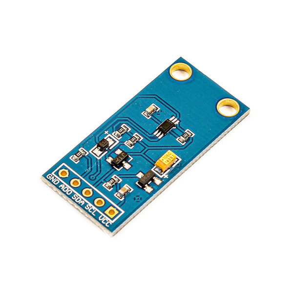
BH1750FVI Sensor Features
BH1750FVI (or BH1750) is a calibrated digital light sensor IC that measures the incident light intensity and converts it into a 16-bit digital number. The BH1750FVI sensor directly gives digital output.
The sensor output can be accessed through an I2C interface. It can measure ambient light intensity and the measurement unit is Lux. Interfacing this module with Arduino is quite easy.
You can download the datasheet of this module here.
/*
Advanced BH1750 library usage example
This example has some comments about advanced usage features.
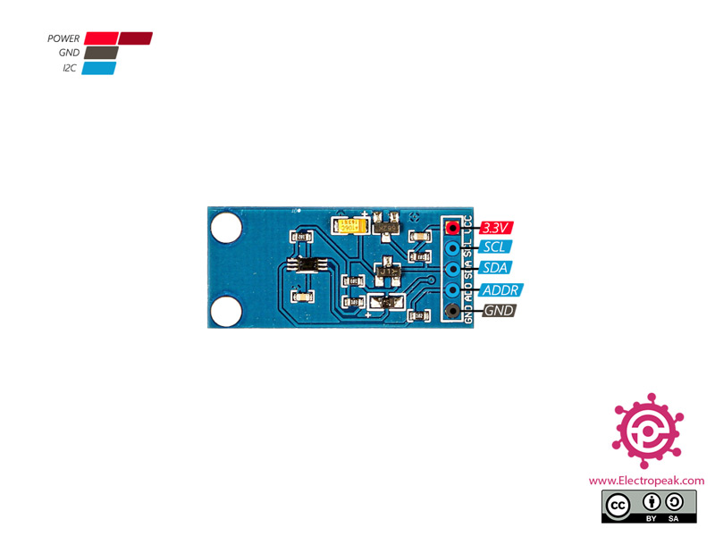
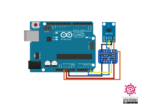
Connection:
VCC -> 3V3 or 5V
GND -> GND
SCL -> SCL (A5 on Arduino Uno, Leonardo, etc or 21 on Mega and Due, on esp8266 free selectable)
SDA -> SDA (A4 on Arduino Uno, Leonardo, etc or 20 on Mega and Due, on esp8266 free selectable)
ADD -> (not connected) or GND
ADD pin is used to set sensor I2C address. If it has voltage greater or equal to
0.7VCC voltage (e.g. you've connected it to VCC) the sensor address will be
0x5C. In other case (if ADD voltage less than 0.7 * VCC) the sensor address will
be 0x23 (by default).
*/
#include <Wire.h>
#include <BH1750.h>
/*
BH1750 can be physically configured to use two I2C addresses:
- 0x23 (most common) (if ADD pin had < 0.7VCC voltage)
- 0x5C (if ADD pin had > 0.7VCC voltage)
Library uses 0x23 address as default, but you can define any other address.
If you had troubles with default value - try to change it to 0x5C.
*/
BH1750 lightMeter(0x23);
void setup(){
Serial.begin(9600);
// Initialize the I2C bus (BH1750 library doesn't do this automatically)
Wire.begin();
// On esp8266 you can select SCL and SDA pins using Wire.begin(D4, D3);
/*
BH1750 has six different measurement modes. They are divided in two groups;
continuous and one-time measurements. In continuous mode, sensor continuously
measures lightness value. In one-time mode the sensor makes only one
measurement and then goes into Power Down mode.
Each mode, has three different precisions:
- Low Resolution Mode - (4 lx precision, 16ms measurement time)
- High Resolution Mode - (1 lx precision, 120ms measurement time)
- High Resolution Mode 2 - (0.5 lx precision, 120ms measurement time)
By default, the library uses Continuous High Resolution Mode, but you can
set any other mode, by passing it to BH1750.begin() or BH1750.configure()
functions.
[!] Remember, if you use One-Time mode, your sensor will go to Power Down
mode each time, when it completes a measurement and you've read it.
Full mode list:
BH1750_CONTINUOUS_LOW_RES_MODE
BH1750_CONTINUOUS_HIGH_RES_MODE (default)
BH1750_CONTINUOUS_HIGH_RES_MODE_2
BH1750_ONE_TIME_LOW_RES_MODE
BH1750_ONE_TIME_HIGH_RES_MODE
BH1750_ONE_TIME_HIGH_RES_MODE_2
*/
// begin returns a boolean that can be used to detect setup problems.
if (lightMeter.begin(BH1750::CONTINUOUS_HIGH_RES_MODE)) {
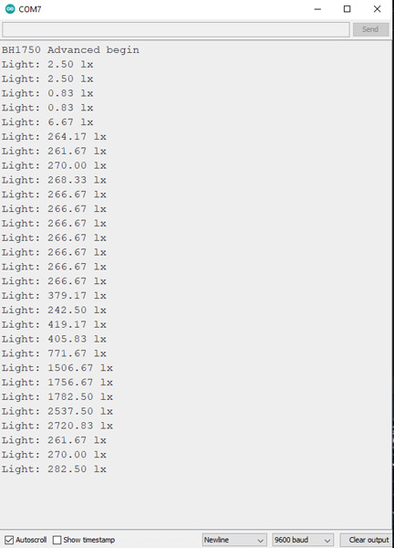
Serial.println(F("BH1750 Advanced begin"));
}
else {
Serial.println(F("Error initialising BH1750"));
}
}
void loop() {
float lux = lightMeter.readLightLevel();
Serial.print("Light: ");
Serial.print(lux);
Serial.println(" lx");
delay(1000);
}
After running the code, you will see the following image in the serial output.