
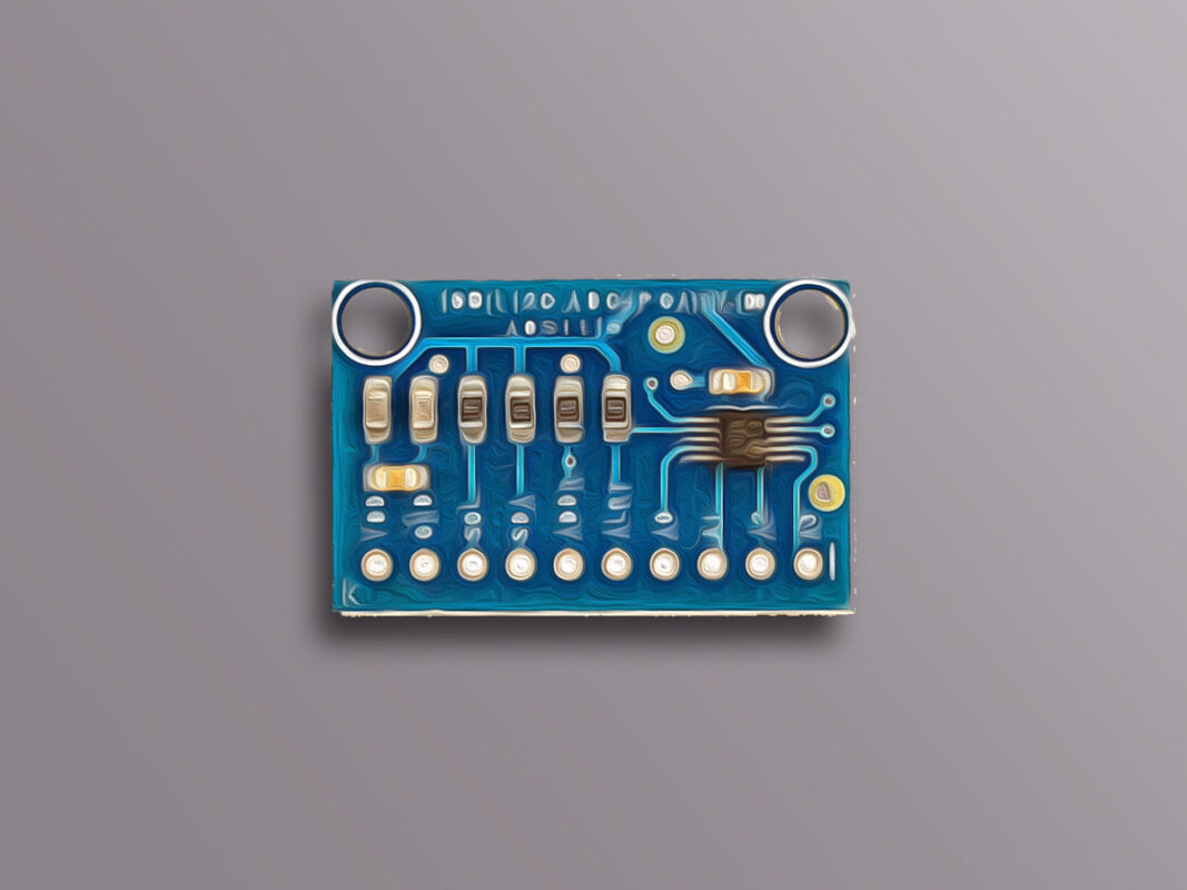
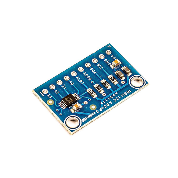
ADS1115 16-Bit ADC Module Features
Almost all microcontrollers come with ADC pins, but they lack high precision. In a lot of projects, analog values need to be measured with high accuracy, or the voltage level of the measured signal is not within the microcontroller measurement range, or even the microcontroller used doesn’t have an ADC pin. In such cases, analog to digital converter modules are used.
ADS1115 module is an analog to digital converter module that has 16-bit precision and can measure a maximum voltage of 7 volts. This module uses I2C communication protocol, so it has a high speed and occupies a small number of the microcontroller pins.
To download the datasheet of ADS1115 module, click here.
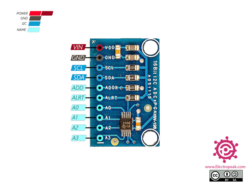
ADS1115 16-Bit ADC Module Pinout
The ADS1115 ADC Module has 10 pins:
- VCC: Module power supply
- GND: Ground
- SCL: I2C Clock Pin
- SDA: I2C Data Pin
- ADDR: I2C Address Pin
- ALRT: Data Ready Interrupt
- A0-3: Analog Inputs 0-3
You can see the pinout of this module in the image below.
Required Materials
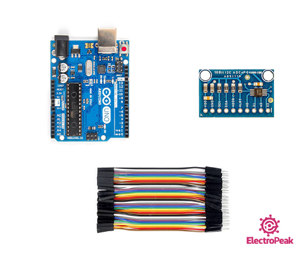
Hardware Components
Software Apps
Interfacing ADS1115 16-Bit ADC Module with Arduino
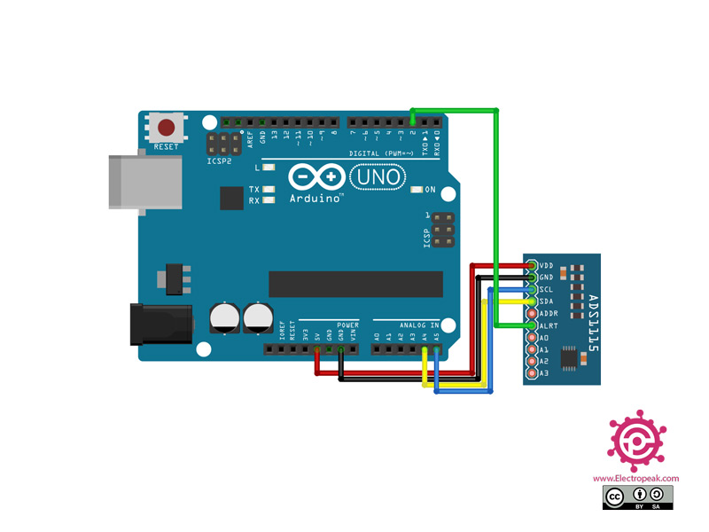
Step 1: Circuit
The following circuit shows how you should connect Arduino to ADS1115 module. Connect wires accordingly.
Step 2: Installing Library
Install the library below on your Arduino IDE.
https://github.com/jrowberg/i2cdevlib/tree/master/Arduino/ADS1115
Note
If you need more help with installing a library on Arduino, read this tutorial: How to Install an Arduino Library
Note
To measure the voltage more accurately, you need to adjust the GAIN. You can choose the right GAIN according to the table below.
| Gain value | Max Voltage |
|---|---|
| ADS1115_PGA_6P144 | ±6.144V |
| ADS1115_PGA_4P096 | ±4.096V |
| ADS1115_PGA_2P048 | ±2.048V |
| ADS1115_PGA_1P024 | ±1.024V |
| ADS1115_PGA_0P512 | ±0.512V |
| ADS1115_PGA_0P256 | ±0.256V |
Step 3: Code
Upload the following code to Arduino. After that, open the Serial Monitor.
/*
  Modify on May 16, 2021
  Modify by MohammedDamirchi base of https://github.com/jrowberg/i2cdevlib/tree/master/Arduino/ADS1115
  Home
*/


// I2C device class (I2Cdev) demonstration Arduino sketch for ADS1115 class
// Example of reading two differential inputs of the ADS1115 and showing the value in mV
// 2016-03-22 by Eadf (https://github.com/eadf)
// Updates should (hopefully) always be available at https://github.com/jrowberg/i2cdevlib
//
// Changelog:
//     2016-03-22 - initial release

/* ============================================
I2Cdev device library code is placed under the MIT license
Copyright (c) 2011 Jeff Rowberg

Permission is hereby granted, free of charge, to any person obtaining a copy
of this software and associated documentation files (the "Software"), to deal
in the Software without restriction, including without limitation the rights
to use, copy, modify, merge, publish, distribute, sublicense, and/or sell
copies of the Software, and to permit persons to whom the Software is
furnished to do so, subject to the following conditions:

The above copyright notice and this permission notice shall be included in
all copies or substantial portions of the Software.

THE SOFTWARE IS PROVIDED "AS IS", WITHOUT WARRANTY OF ANY KIND, EXPRESS OR
IMPLIED, INCLUDING BUT NOT LIMITED TO THE WARRANTIES OF MERCHANTABILITY,
FITNESS FOR A PARTICULAR PURPOSE AND NONINFRINGEMENT. IN NO EVENT SHALL THE
AUTHORS OR COPYRIGHT HOLDERS BE LIABLE FOR ANY CLAIM, DAMAGES OR OTHER
LIABILITY, WHETHER IN AN ACTION OF CONTRACT, TORT OR OTHERWISE, ARISING FROM,
OUT OF OR IN CONNECTION WITH THE SOFTWARE OR THE USE OR OTHER DEALINGS IN
THE SOFTWARE.
===============================================
*/

#include "ADS1115.h"

ADS1115 adc0(ADS1115_DEFAULT_ADDRESS);

// Wire ADS1115 ALERT/RDY pin to Arduino pin 2
const int alertReadyPin = 2;

void setup() {
    //I2Cdev::begin();  // join I2C bus
    Wire.begin();
    Serial.begin(115200); // initialize serial communication

    Serial.println("Testing device connections...");
    Serial.println(adc0.testConnection() ? "ADS1115 connection successful" : "ADS1115 connection failed");

    adc0.initialize(); // initialize ADS1115 16 bit A/D chip

    // We're going to do single shot sampling
    adc0.setMode(ADS1115_MODE_SINGLESHOT);

    // Slow things down so that we can see that the "poll for conversion" code works
    adc0.setRate(ADS1115_RATE_250);

    // Set the gain (PGA) +/- 6.144v
    // Note that any analog input must be higher than –0.3V and less than VDD +0.3
    adc0.setGain(ADS1115_PGA_6P144);
    // ALERT/RDY pin will indicate when conversion is ready

    pinMode(alertReadyPin,INPUT_PULLUP);
    adc0.setConversionReadyPinMode();

    // To get output from this method, you'll need to turn on the
    //#define ADS1115_SERIAL_DEBUG // in the ADS1115.h file
    #ifdef ADS1115_SERIAL_DEBUG
    adc0.showConfigRegister();
    Serial.print("HighThreshold="); Serial.println(adc0.getHighThreshold(),BIN);
    Serial.print("LowThreshold="); Serial.println(adc0.getLowThreshold(),BIN);
    #endif
}

/** Poll the assigned pin for conversion status
 */
void pollAlertReadyPin() {
  for (uint32_t i = 0; i<100000; i++)
    if (!digitalRead(alertReadyPin)) return;
   Serial.println("Failed to wait for AlertReadyPin, it's stuck high!");
}

void loop() {

    // The below method sets the mux and gets a reading.
    adc0.setMultiplexer(ADS1115_MUX_P0_NG);
    adc0.triggerConversion();
    pollAlertReadyPin();
    Serial.print("A0: "); Serial.print(adc0.getMilliVolts(false)); Serial.print("mV\t");

    adc0.setMultiplexer(ADS1115_MUX_P1_NG);
    adc0.triggerConversion();
    pollAlertReadyPin();
    Serial.print("A1: "); Serial.print(adc0.getMilliVolts(true)); Serial.print("mV\t");

    adc0.setMultiplexer(ADS1115_MUX_P2_NG);
    adc0.triggerConversion();
    pollAlertReadyPin();
    Serial.print("A2: "); Serial.print(adc0.getMilliVolts(true)); Serial.print("mV\t");

    adc0.setMultiplexer(ADS1115_MUX_P3_NG);
    // Do conversion polling via I2C on this last reading:
    Serial.print("A3: "); Serial.print(adc0.getMilliVolts(true)); Serial.print("mV");

    Serial.println(digitalRead(alertReadyPin));
    delay(500);
*/
This code is for displaying the values received by A0~3 pins.
By following this step-by-step guide, you have successfully interfaced the ADS1115 16-Bit ADC module with Arduino, enabling high-precision analog measurements. The I2C communication protocol ensures efficient data transfer, while the provided circuit diagram, library installation instructions, and sample code assist in accurate voltage measurement. Utilize the knowledge gained here to enhance your projects requiring precise analog data acquisition.
Remember to make any necessary adjustments to the GAIN setting to suit your specific requirements. With the ADS1115 module and Arduino working together, you can achieve exceptional results in your analog measurement projects.
