
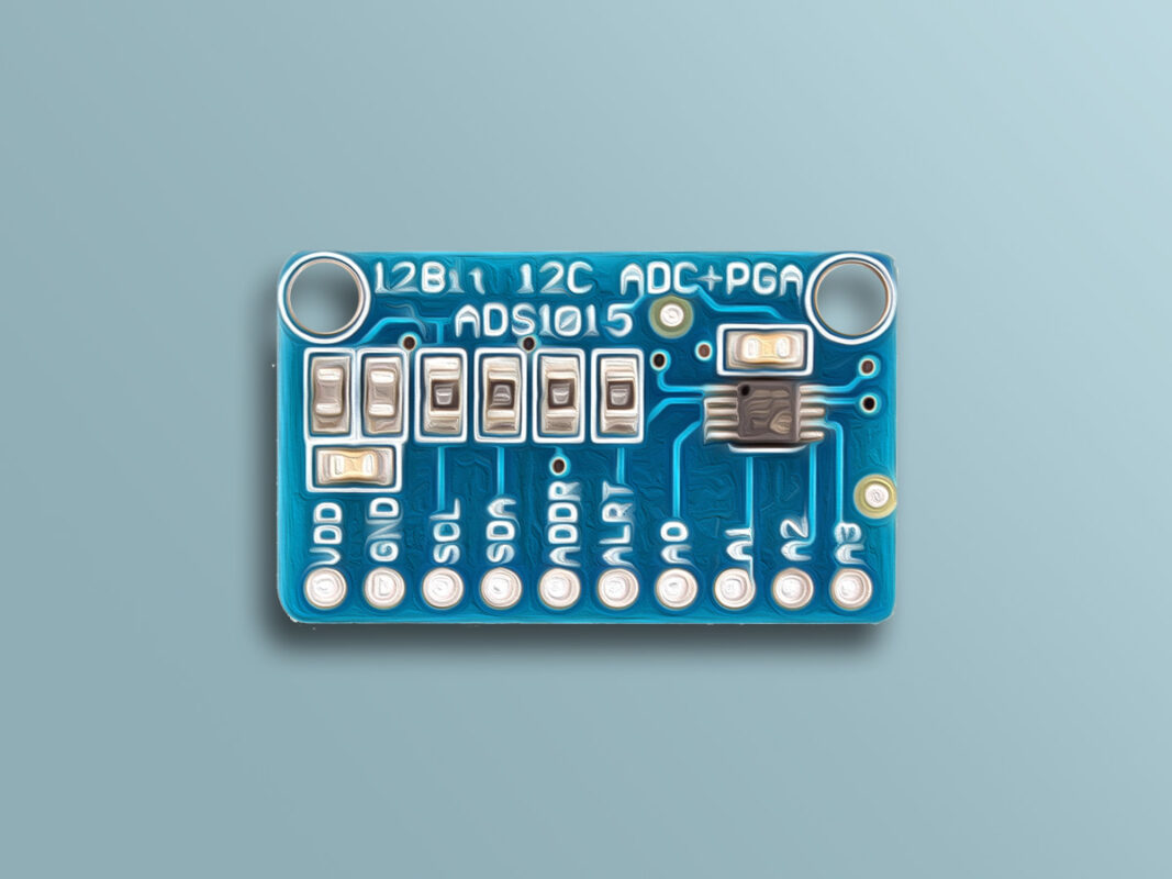
ADS1015 12-Bit ADC Module Features
Almost all microcontrollers come with ADC pins, but they lack high precision. In a lot of projects, analog values need to be measured with high accuracy, or the voltage level of the measured signal is not within the microcontroller measurement range, or even the microcontroller used doesn’t have an ADC pin. In such cases, analog to digital converter modules are used.
ADS1015 module is an analog to digital converter module with 12-bit precision and can measure a maximum voltage of +0.3VDD volts. This module uses I2C communication protocol, so it has a high speed and occupies a few of the microcontroller pins.
To download the datasheet of ADS1015 module, click here.
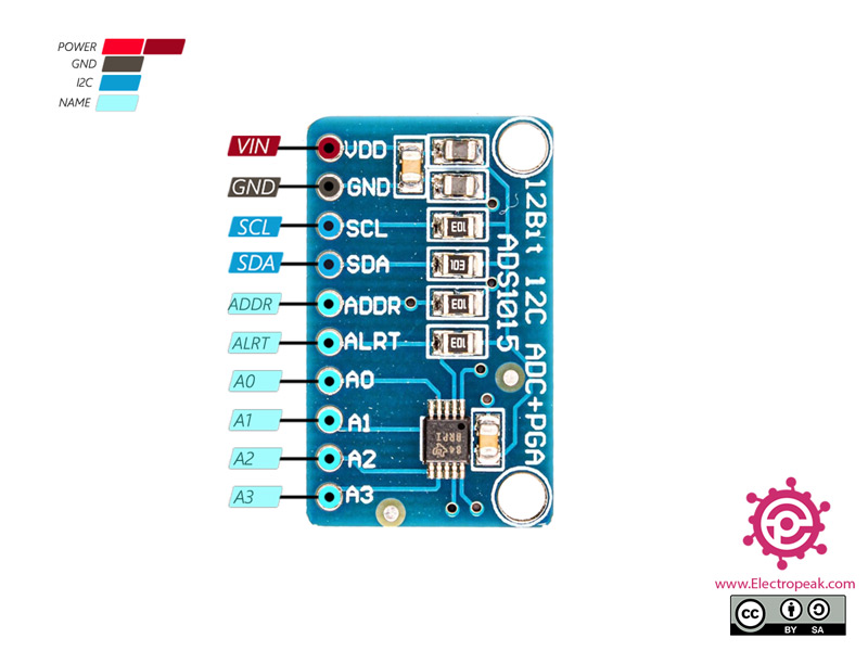
ADS1015 12-Bit ADC Module Pinout
The ADS1015 ADC Module has 10 pins:
- VCC: Module power supply
- GND: Ground
- SCL: I2C Clock Pin
- SDA: I2C Data Pin
- ADDR: I2C Address Pin
- ALRT: Data Ready Interrupt
- A0-3: Analog Inputs 0-3
You can see the pinout of this module in the image below.
Required Materials

Hardware Components
Software Apps
Interfacing ADS1015 12-Bit ADC Module with Arduino
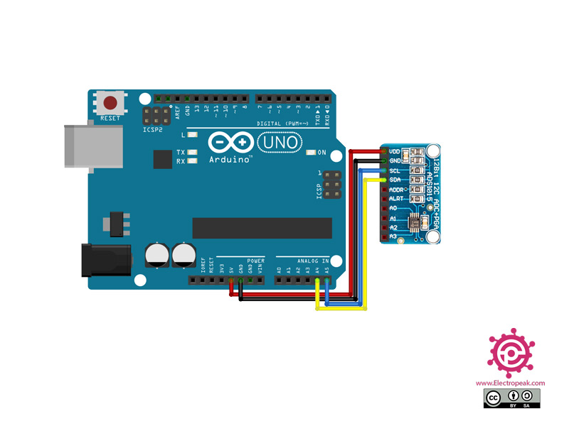
Step 1: Circuit
The following circuit shows how you should connect Arduino to ADS1015 module. Connect wires accordingly.
Step 2: Installing Library
Install the library below on your Arduino IDE.
Note
If you need more help with installing a library on Arduino, read this tutorial: How to Install an Arduino Library
Note
To measure the voltage more accurately, you need to adjust the GAIN value. You can choose the right value for GAIN according to the table below.
| PGA value | Max Voltage |
|---|---|
| 0 | ±6.144V |
| 1 | ±4.096V |
| 2 | ±2.048V |
| 3 | ±1.024V |
| 4 | ±0.512V |
| 5 | ±0.256V |
Step 3: Code
Upload the following code to Arduino.
/*
  Modify on May 19, 2021
  Modify by MohammedDamirchi base https://github.com/RobTillaart/ADS1X15  https://electropeak.com/learn/
*/

//
//    FILE: ADS_read.ino
//  AUTHOR: Rob.Tillaart
// VERSION: 0.2.1
// PURPOSE: read analog inputs - straightforward.
//

// test
// connect 1 potmeter per port.
//
// GND ---[   x   ]------ 5V
//            |
//
// measure at x (connect to AIN0).
//

#include "ADS1X15.h"

ADS1115 ADS(0x48);

void setup()
{
  Serial.begin(115200);
  Serial.println(__FILE__);
  Serial.print("ADS1X15_LIB_VERSION: ");
  Serial.println(ADS1X15_LIB_VERSION);

  ADS.begin();
}

void loop()
{
  ADS.setGain(0);

  int16_t val_0 = ADS.readADC(0);
  int16_t val_1 = ADS.readADC(1);
  int16_t val_2 = ADS.readADC(2);
  int16_t val_3 = ADS.readADC(3);

  float f = ADS.toVoltage(1);  // voltage factor

  Serial.print("Analog0: "); Serial.print(val_0); Serial.print('\t'); Serial.print(val_0 * f, 3);
  Serial.print("\tAnalog1: "); Serial.print(val_1); Serial.print('\t'); Serial.print(val_1 * f, 3);
  Serial.print("\tAnalog2: "); Serial.print(val_2); Serial.print('\t'); Serial.print(val_2 * f, 3);
  Serial.print("\tAnalog3: "); Serial.print(val_3); Serial.print('\t'); Serial.print(val_3 * f, 3);
  Serial.println();

  delay(1000);
}

// -- END OF FILE
*/
This code is for displaying the values received by A0~3 pins.
