
Overview
Sometimes in electronic projects, you need to use two or more microcontrollers in your circuit at the same time. Normally, these microcontrollers are connected to each other and keep transmitting data with one another. The transmitting of data between two or more microcontrollers can be done with several communication protocols such as SPI, UART, CAN, USB, etc. Another one which we will be covering here in this tutorial is I2C (Inter-Integrated Circuit) protocol.
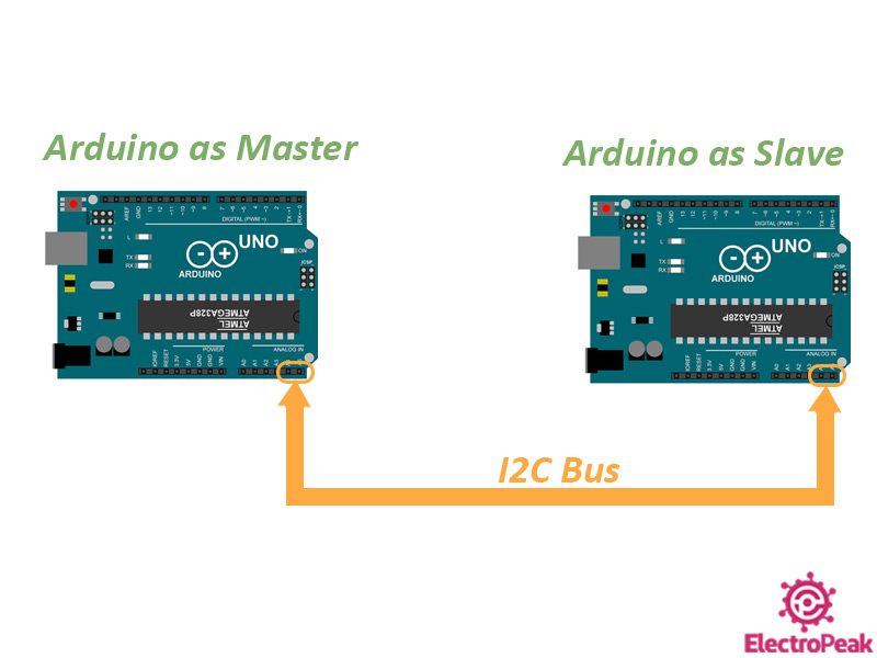
Using this protocol, one of the microcontroller will be the master and the other one will be the slave, and you’ll be able to transmit data between them. The microcontroller that is the master would start communication and provides the clock line SCL.
In this tutorial, two Arduino Uno boards are used as two AVR microcontrollers. This way, two or more Arduino Boards can be connected to each other through I2C protocol. And of them would the master and the other one would be the slave.
What You Will Learn
In this tutorial, we are going to have an overview on the I2C protocol and the Arduino library “wire” which is the specific library for I2C protocol. You will be familiar with lots of its useful functions and will learn how to transmit data between two Arduino Boards through I2C communication protocol. Finally, we will have a circuit containing two Arduino Boards along with two LEDs and two potentiometers to see the results in practice.
Using the potentiometer of the master Arduino board, we will control the LED connected to the slave Arduino board, and vice versa. Meaning that we will control the output of the slave using the input of the master, and also control the output of the master using the input of the slave. The transmitted data will also be displayed on the Serial Monitor.
Finally, a simple circuit like the following is made, and the results can be seen in practice.
What Is I2C Communication Protocol, and How Does It Work?
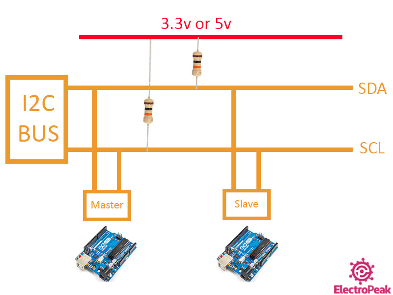
I2C, short for “Inter-Integrated Circuit” is a communication protocol which is also known by the short term IIC. This communication protocol is widely used in microcontrollers. In this communication, masters and slaves (Masters are usually the main components like microcontrollers and Slaves are the sensors, modules and other components used in the circuit.) communicate through 2 lines:
- SDA (Serial Data): The line to transmit and receive data between Master and Slave
- SCL (Serial Clock): The line to send the clock (used for synchronization)
Note
In Arduino Uno, the pins A4 and A5 are the SDA and SCL lines, respectively.
In other boards and microcontrollers, these pins might be different. In the case of using other microcontrollers, you can easily figure out the I2C pins by checking their datasheet.
The most important features of the I2C communication protocol are the following:
- It’s not so fast (But fast enough for most applications)
- Suitable for short distances (e.g. maximum distance in 100KHz frequency is 1 meter)
- Synchronous communication
- Data is transmitted serially
- Logic level can be 3.3V or 5V
There are two types of devices that connect to the I2C bus in the I2C protocol: The master and the slave. In this protocol, multiple slaves can be connected to a single master, like a microcontroller. And also, a single slave can be controlled and monitored by multiple masters, but only one of the masters can be active at a time. Each master can select which slave to communicate with. The selection is done using the slave’s 7-bit addresses (10-bit in some cases). So, there can be approximately 128 slave devices connected to the I2C bus. So, in other words, each slave has its own specific I2C address and there is no address for the masters.
The data transmitted in the I2C bus is synchronized by clock line, SCL. The master is responsible for the synchronization.
Note
The 2 SDA and SCL pins need to pulled-up in the circuit. At high speeds like 400kbps, a 2KΩ resistor is enough, and at lower speeds like 100kbps, a 10KΩ resistor needs to be used.
The “Wire” Library
To work with the I2C protocol, we use the “Wire” library, which is one of the Arduino IDE libraries. Working with the I2C communication protocol would be so easy using this library. This library has a lot of useful functions, including:
- begin(): Using this function, you can determine the Arduino board to be the master or the slave.
- requestFrom(): this function is used on the master side and can be used to request data transmission from the slave. The number of bytes and also the slave address are specified in this function.
- beginTransmission(): This function which is used by the master starts the communication with a special slave using its address.
- endTransmission(): The communication started by the previous function ends using this function.
- write(): Both the master and the slave use this function to send data to the I2C bus.
- available(): Both the master and the slave use this function to calculate the number of bytes received (by the “read()” function)
- read(): The function for reading a byte of data from the I2C bus. (used by Both the master and the slave)
- setClock(): This is used by the master to set the clock frequency.
- onReceive(): This is defined as a function by the slave and is called when data is received from the master.
- onRequest(): This is defined as a function by the slave and is called when data is requested by the master.
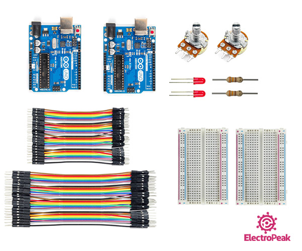
Required Material
Hardware Components
Software Apps
Connect Two Arduino Boards, One of Them as the Master and the Other as the Slave
Now, we have reached the main part of the tutorial and are going to establish a communication between two Arduino Boards through I2C protocol. One of the Arduino Boards acts as the master and the other as the slave. First, its practical circuit is made. Then, we will explain its program and after uploading the programs on the two Arduino boards, we can see the results.
Step 1: Circuit
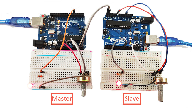
The following circuit shows how you should connect the two Arduino boards to other components:
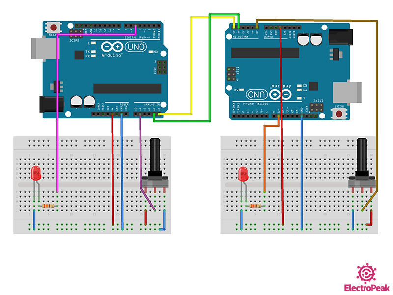
As you can see in the image above, the communication between the Arduino Boards is only through the I2C bus. The Arduino Board on the left is the master and the one on the right is the slave. Each Arduino Board has a potentiometer and an LED connected to it. We will control each LED using the Arduino Board on the other side.
Tip
If both Arduino Boards are connected to the same computer, you don’t need to connect their GND pins to each other. But, if you have connected the Arduino Boards to two different computers, you should connect their GND pins.
Step 2: Master Side code
Once you have prepared the circuit, you should upload the codes of the master and the slave on their Arduino Boards. First, upload the following code on the Arduino acting as the master:
/*
  Made on 8 June 2021
  By Amirmohammad Shojaei
  Home
*/

#include <Wire.h>

int value = 0;

void setup() {
  Wire.begin(); // join i2c bus (address optional for master)
  Serial.begin(9600);

  pinMode(5, OUTPUT);
}

void loop() {
  int y = analogRead(A1);         //Read from A1 & Save to value
  value = map(y, 0, 1023, 0, 255);

  Wire.beginTransmission(8); // transmit to device #8
  Wire.write("Master value :  ");         // sends these bytes
  Wire.write(value);              // sends one byte
  Wire.endTransmission();    // stop transmitting

  Wire.requestFrom(8, 1);    // request 1 byte from slave device #8
  while (Wire.available()) { // slave may send less than requested
    int c = Wire.read(); // receive a byte as character

    analogWrite(5, c);
    Serial.print("Slave value : ");
    Serial.println(c);         // print the character
  }

  delay(100);
}
We want to send the value of the potentiometer on the master side to the slave and receive a byte of the potentiometer data by the slave, display it on the Serial Monitor and control the brightness of the LED with it.
The following points are worth mentioning regarding the code above:
- First, we include the “Wire” library.
- We start working with library using the “begin()” function.
- In the main loop, the analog input is stored in the variable “value” and converted to the range of 0-255.
- Then, using the function “beginTransmission(8)”, the address of the slave is entered and I2C communication is started for data transfer. Then, using the function “write()”, some characters containing some letters signs are sent, and then, a byte of the actual data is sent. Finally, the transmission of data is ended using the command line “endTransmission()”.
- In the next step, the master requests to receive one byte of data from the slave that has the address “8”. This can be done using the command line “requestFrom(8,1)”. After that, we store the data received from the slave–this data is in the range 0-255- and control the LED brightness with it. This value is also displayed on the Serial Monitor.
Note
Make sure you have selected the right PORT before uploading the code.
Step 3: The Code of the Slave Side
Now, upload the following code on the Arduino acting as the slave:
/*
  Made on 8 June 2021
  By Amirmohammad Shojaei
  Home
*/

#include <Wire.h>

int x;
int value=0;

void setup() {
  Wire.begin(8);                // join i2c bus with address #8
  Wire.onRequest(requestEvent); // register event
  Wire.onReceive(receiveEvent); // register event
  Serial.begin(9600);    // start serial for output

  pinMode(9,OUTPUT);
}

void loop() {
  delay(100);
  analogWrite(9,x);

  int t=analogRead(A0);          //Read from A0 & Save to value
  value=map(t,0,1023,0,255);
}

// function that executes whenever data is received from master
void receiveEvent() {
  while (1 < Wire.available()) { // loop through all but the last
    char c = Wire.read();       // receive byte as a character
    Serial.print(c);         // print the character
  }
   x = Wire.read();    // receive byte as an integer
   Serial.println(x);         // print the integer
}

// function that executes whenever data is requested by master
void requestEvent() {
  Wire.write(value); // respond with message of 1 byte
  // as expected by master
}
We want to send the potentiometer value of the slave to the master and receive the data sent from the master. And then, display it on the Serial Monitor and control the LED brightness with it.
The following points are worth mentioning regarding the code above:
- First, we include the “Wire” library.
- We start working with the library using the “begin(8)” function. The slave address is determined here.
- The functions “onRequest” and “onReceive” are used to request sending data and receiving data, respectively. We will also explain the inside of each functions in the following.
- The “receiveEvent()” function: Using this function, the data sent from the master is received. First, in the while loop, all bytes except for the last one are received. These bytes are the characters of the phrase “Master value:”. After the while loop, the last byte, which is the value of the potentiometer on the master side, is received and stored in the variable “x”.
- requestEvent(): When the master requests for data, the slave sends the wanted data to the master using this function and the “write()” command line.
- Now, in the main loop, the value “x” which is sent from the master is used to control the brightness of the LED. In other words, by rotating the potentiometer on the master side, the value of “x” changes, and the brightness of the LED changes as the result.
- In the rest of the main loop, the value of the potentiometer is read, converted to a value ranging 0-255, stored in the variable “x” and prepare it to be sent to the master.
Note
If you’re using the same computer for programming the two Arduino boards, pay attention to the PORT you have selected for each Arduino board. To upload the code of the slave, open a new .ino file, so you can upload codes of each Arduino board without any problem.
Step 4: Results
After successfully uploading the codes on both Arduino Boards, open the Serial Monitor of both PORTS and see the changes of the values and the brightness of LEDs by rotating the potentiometers. The result is similar to the following video:
In the video above, it can be seen that you can control the LED of the slave side by rotating the potentiometer of the master side. The value can also be seen on the Serial Monitor of the slave side. The same thing goes for the master, too. By rotating the potentiometer on the slave side, the LED brightness on the master side and also the value displayed on the Serial Monitor changes.
What’s Next?
After completing this tutorial, the following topics can be done as the next step:
- Connect different boards to each other, like raspberry pies, ESP32 & ESP8266 Boards
- Using different sensors as the slaves
- Try to send and receive larger data
- Use different communication protocols like SPI, CAN, etc. to connect 2 Arduino Boards to each other
- Use two masters and multiple slaves connected to the same I2C bus

Comments (2)
Excellent tutorial. One question , should “x” in the slave be declared as volatile?
Hello Brenan,
You can declare ‘x’ as volatile. If you don’t declare it, there is no problem.