
Overview
In this tutorial, you’ll get to know about liquids level detection with Arduino. First, you’ll see some information about the water level sensor, and then you’ll learn how to use this module with some practical examples.
What You Will Learn
- What water level detecting is
- How water level sensor works
- How to use a water level sensor with Arduino
What Is Water Level Detection?
How Water Level Sensor Works
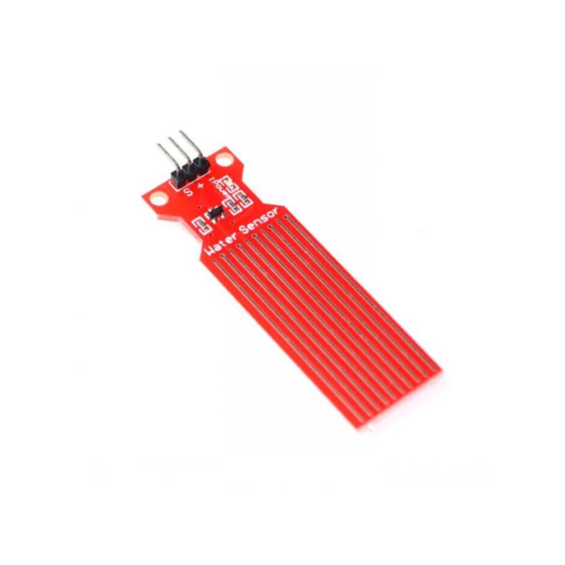
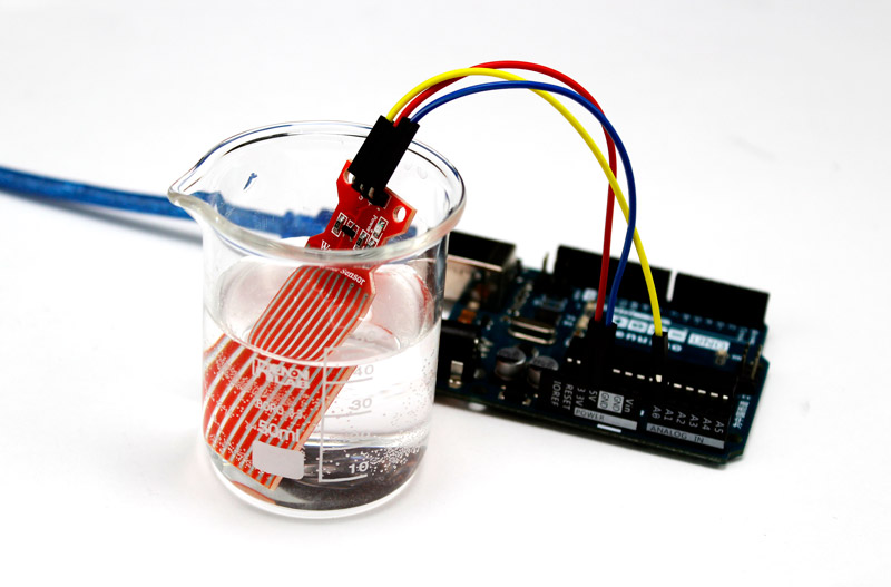
This module, which is one of the most widely used modules for detecting the liquid level, works on the basis of resistance change. On this module, there are parallel lines of conductivity that are connected to the Ground and are in fact the path of electric current. Water is a good conductor so when these lines are in the water, they will be short circuit, and the resistance of the module decreases.
By fixing the module on the liquid container, the variable resistance sets on a specific value based on the water level. As the water level increases, the resistance of the connected copper path will decrease, therefore more current flows through the circuit (in practice, the sensor acts like a variable resistor). With this method, the sensor can measure the water level.
The output of this sensor is analog voltage. The higher the liquid level, the higher the output voltage.
Water Level Sensor Pinout
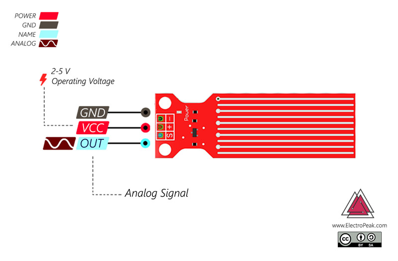
This sensor has 3 pins:
- +: Module power supply – 2-5 V
- -: Ground
- S: Analog output
You can see pinout of this module in the image below.
Required Materials
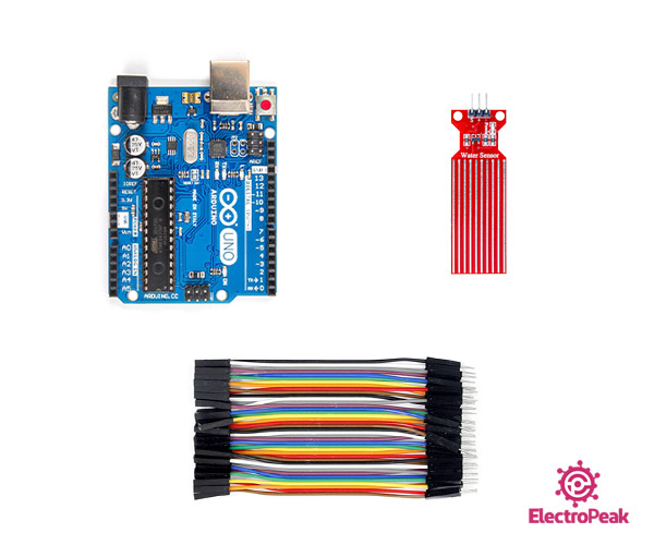
Hardware Components
Software Apps
Interfacing Water Level Sensor with Arduino
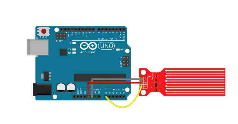
Step 1: Circuit
Step 2: Code
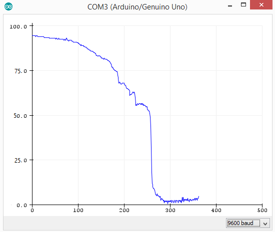
Upload the following code on your Arduino board and open the serial monitor window. Place the sensor in water, and you can see the results on your serial monitor window.
/* Water level sensor
 *  by Hanie Kiani
 *  https://electropeak.com/learn/
 */
const int analogInPin = A0;
int sensorValue = 0;

void setup() {
 Serial.begin(9600);
}

void loop() {
 sensorValue = analogRead(analogInPin);
 Serial.print("Sensor = " );
 Serial.print(sensorValue*100/1024);
 Serial.println("%");
 delay(1000);
}
Use the Liquid Level Sensor as a Rain Detector
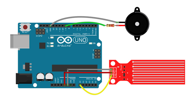
You can also use the water level sensor to detect rain with a buzzer. To detect whether it is raining, position the sensor horizontally so that raindrops can fall on the sensor and increase the value of the pin S.
When the sensor starts getting wet, the buzzer will start beeping every few seconds. And when the module becomes completely wet, the buzzer warns with louder sound and will continue beeping nonstop.
Step 1: Circuit
Step 2: Code
/*
   * Rain Detector with Water level sensor
 *  by Hanie kiani
 *  https://electropeak.com/learn/
 */
const int sensorMin = 0;     // sensor minimum
const int sensorMax = 1024;  // sensor maximum
const int buzzer = 9;
void setup() {
  Serial.begin(9600);
  pinMode(buzzer, OUTPUT);
}
void loop() {
int sensorReading = analogRead(A0);
int range = map(sensorReading, sensorMin, sensorMax, 0, 3);
  // range value:
  switch (range) {
 case 0:    // Sensor is wet
    Serial.println("ٌWet!");
    tone(buzzer, 5000);
    break;
 case 1:    // Sensor getting wet
    Serial.println(" Warning");
     tone(buzzer, 1000 , 5);
    break;
 case 2:    // Sensor dry
    Serial.println("Dry");
    noTone(buzzer);
    break;
  }
  delay(10);  // delay between reads
} map() function divides the sensor range 0 to 1024 into 3 sections. tone(buzzer, 5000);tone() function sends a PWM signal on the buzzer pin so the buzzer will make a sound.
The first argument specifies the output pin, and the second one determines the PWM frequency. It can also have a third argument standing for the signal duration. What’s Next?
- Try to use the SMS module (like the Sim800 module) with your rain detector, so that it can inform you the raining by sending a message on your phone.

Comments (2)
Can I know the unit of the analogue value from the water level sensor output?
It’s just an analog value in volts that has an direct relationship with the liquid level. The higher the liquid level, the greater the output value.