
Product added to cart

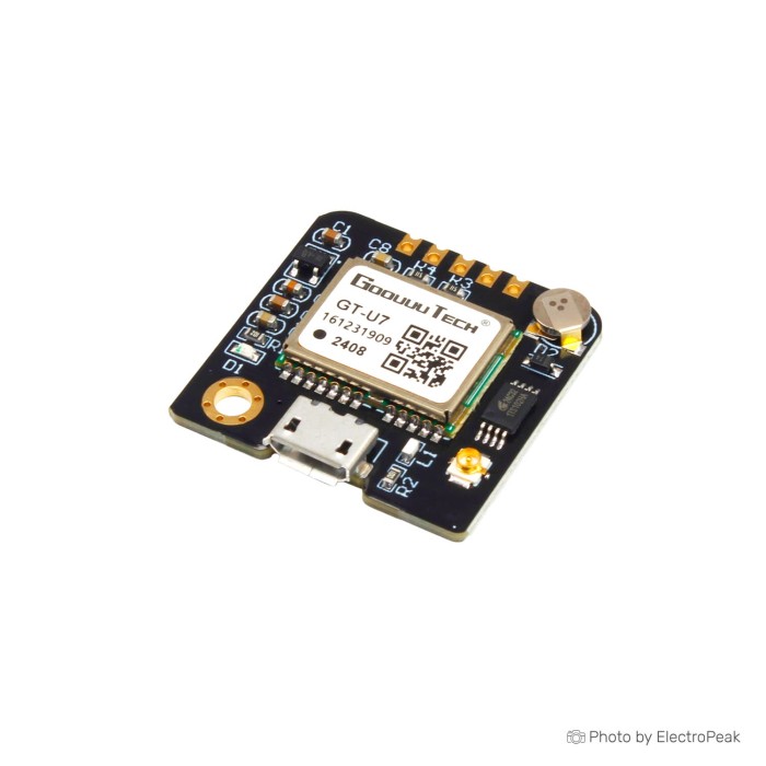
Goouuu Tech GT-U7 GPS Module
$7.0400
In stock
SKU
SEN-15-021
Volume discounts:
- +25 3 % $6.8100
- +50 5 % $6.6900
- +100 7 % $6.5700
- +300 8 % $6.4500
- +500 10 % $6.3400
Ships in 2-3 business days, then:
Free delivery in 12-15 days by Tracked Economic Shipping on orders over $100.
Free delivery in 7-10 days by Express Shipping on orders over $300.
More shipping info

Shop with confidence Learn More

GT-U7 GPS Module Review
The Goouuu Tech GT-U7 GPS Module is a GPS receiver that provides location tracking through micro USB and TTL UART interfaces. It pairs an IPEX-connected active antenna with standard NMEA serial output at 9600 baud. Onboard EEPROM retains modified configuration settings across power cycles, while the dual communication paths let you check diagnostics directly on a computer before wiring the board to an embedded controller. It suits development benches and maker builds that need accessible location data and straightforward serial inspection under an open sky.
This board suits outdoor asset loggers, telemetry trackers, and microcontroller projects where builders can confirm serial streams and verify signal reception directly. Projects requiring a traceable receiver IC, guaranteed u-blox silicon identity, verified 5V UART logic levels, or certified positioning accuracy in safety-critical systems should consider fully documented alternatives in our GPS and location modules catalog.
Specifications of Goouuu Tech GT-U7 GPS Module
- Operation Voltage: 3.6V - 5V (or direct USB power supply)
- Operation Current: 30mA
- Dimensions: 74x51x12.7mm
- Weight: 5.7g (0.2 ounces)
- GPS Chipset: 7th generation (compatible with NEO-6M software)
- Antenna Interface: IPEX connector for GPRS/GPS/BT
- Communication Interface: micro USB and UART (TTL)
- Baud Rate: 9600 (modifiable)
- Positioning Accuracy: 1~2.5m
- Onboard Memory: E2PROM for saving parameter data
- Output Format: NMEA, compatible with NEO-6M
GT-U7 GPS Module Specifications Explained
Evaluating a GPS module means separating basic electrical requirements from physical packaging and real-world radio-reception constraints. The GT-U7 combines standard serial protocols with an external antenna format, so integration is straightforward once you understand its operating limits.
| Specification | Listed Value | Why It Matters |
|---|---|---|
| Communication Interface | micro USB and UART (TTL) | Dual interfaces allow bench testing directly over USB via a PC serial terminal before committing to microcontroller wiring, reducing debugging time on custom firmware. |
| Baud Rate | 9600 (modifiable) | 9600 baud serves as the factory default serial communication rate. Microcontroller sketches and serial terminals must match this rate to prevent garbled text. |
| Output Format | NMEA, compatible with NEO-6M | NMEA 0183 output is plain ASCII text, allowing easy sentence parsing in Arduino libraries or custom software routines without proprietary binary decoders. |
| Operation Voltage | 3.6V - 5V (or direct USB power supply) | Flexible supply input accommodates direct USB power or typical 5V system rails. It does not guarantee that the UART logic lines tolerate 5V signals. |
| Operation Current | 30mA | Represents baseline running current. Active satellite search during cold starts draws more current, so power supplies should supply adequate overhead. |
| Positioning Accuracy | 1~2.5m | Nominal open-sky horizontal precision. Actual precision varies based on satellite geometry, weather, multipath interference, and antenna placement. |
| Dimensions | 74x51x12.7mm | The published measurement often reflects package or assembly boundaries. Measure the physical bare PCB directly before 3D printing or machining an enclosure. |
| Onboard Memory | E2PROM for saving parameter data | Stores baud rate and output sentence configuration across reboots, avoiding the need for host initialization scripts on every startup. |
For software integration, review standard techniques for reading GPS data with Arduino to understand sentence parsing and buffer management.
GT-U7 GPS Module USB, UART and Arduino Compatibility
The GT-U7 provides two communication paths: a micro-USB port that enumerates as a virtual COM port on host computers, and a standard 0.1-inch-spaced UART pin header for embedded microcontrollers. This arrangement supports rapid bench validation. Connect the board to a PC with a data-capable micro-USB cable to verify satellite acquisition and view raw NMEA sentences in any standard serial monitor set to 9600 baud before writing microcontroller code.
For microcontrollers such as Arduino Uno, Mega, ESP32, ESP8266, STM32, or Raspberry Pi, establish a common ground, connect module TXD to the host microcontroller RXD, and wire host TXD to module RXD only when sending configuration commands. The module accepts 3.6V to 5V on its power pin, but the UART I/O lines are not documented as 5V-tolerant. With a 5V microcontroller such as an Arduino Uno, route the host TX pin through a logic-level shifter or simple resistor divider to protect the module RXD pin.
| Host Platform | Interface Used | Logic Level Compatibility | Connection Notes |
|---|---|---|---|
| PC (Windows / Linux / macOS) | micro USB | Standard USB signaling | Requires a data-capable USB cable; verify detected COM port and set terminal to 9600 baud. |
| Arduino Uno / Mega (5V) | TTL UART | 5V host / 3.3V module I/O | Connect module TXD directly to Arduino RX; step down Arduino TX to module RXD using level shifting. |
| ESP32 / ESP8266 (3.3V) | TTL UART | Direct 3.3V compatible | Direct connection to hardware serial pins; connect TXD to RX, RXD to TX, and common ground. |
| Raspberry Pi (3.3V) | TTL UART or USB | Direct 3.3V compatible | Disable Linux serial console on UART pins before reading NMEA data, or plug directly into USB. |
| STM32 Boards (3.3V) | TTL UART | Direct 3.3V compatible | Direct wiring to any available USART port running at 9600 baud. |
For clean prototyping between the module pin headers and your development board, use reliable jumper wires for UART GPS wiring. For PC-only or enclosed Raspberry Pi setups where direct UART pins are unnecessary, an enclosed USB GPS receiver for PC or Raspberry Pi with an integrated 2-meter cable offers a more rugged plug-and-play option.
GT-U7 GPS Module Limitations and First-Fix Expectations
Reliable first fixes depend on the physical constraints of satellite reception. The GT-U7 relies entirely on an external active antenna connected to its onboard IPEX connector; it has no integrated ceramic patch antenna. Powering the board without the antenna firmly seated will result in zero satellite locks. Test outdoors with an unobstructed view of the sky. Indoors, near metal roofs, or beside noisy switching regulators, the module will output valid NMEA text sentences containing timestamps and empty coordinate fields. This indicates that the receiver is waiting for sufficient satellite ephemeris data.
Cold starts on an uninitialized receiver can take from 30 seconds to several minutes under an open sky while the module downloads orbital data from visible satellites. A common mistake is assuming the module is defective when an indoor bench test produces blank coordinate strings.
Factor these technical limitations and documentation discrepancies into your purchase decision:
- Receiver Identity Ambiguity: Product documentation notes a 7th-generation chipset compatible with NEO-6M software, while linked technical datasheets reference a u-blox 6 positioning engine. The exact silicon marking on the receiver is unconfirmed. Software compatibility is therefore limited to standard NMEA strings rather than proprietary binary configuration commands or official u-center tooling.
- Unbuffered 5V Logic: While the board accepts up to 5V on its VCC pin, the serial RX line is unbuffered. Driving it directly from 5V logic risks premature pin degradation.
- Baud Rate Defaults: Many beginner GPS sample sketches default to 4800 baud. Because the GT-U7 outputs at 9600 baud, mismatched software configurations display illegible characters.
- Physical Board Dimensions: The listed 74x51x12.7mm specification does not match typical bare PCB dimensions for this family, which measure closer to 27.5x26.5mm. Verify the physical board size upon receipt before fabricating rigid enclosures.
For a replacement active antenna, verify the plug type carefully. An external replacement active GPS antenna with an SMA termination requires a matching adapter cable to interface with the GT-U7 IPEX socket. Satellite GPS is unsuitable for indoor tracking projects where signals cannot penetrate building materials. Consider an UWB indoor positioning module, which uses ultra-wideband RF signals to achieve 10 cm indoor accuracy using dedicated anchor beacons.
GT-U7 GPS Module Alternatives: NEO-7M, NEO-8M and USB GPS
GPS hardware choice depends on your interface requirements, enclosure needs, and whether the project demands multi-constellation satellite reception. The GT-U7 is set up for dual-interface bench prototyping, while the alternatives below address specific design constraints.
| Module | Primary Interface | Operating Voltage | Satellite Systems | Best Application |
|---|---|---|---|---|
| Goouuu Tech GT-U7 | micro USB & UART | 3.6V - 5V (or USB) | GPS (NMEA output) | Dual-interface bench prototyping and general hobby tracking. |
| GY-NEO-7M V2 | TTL UART | 2.7V - 3.3V DC | GPS, GLONASS, BeiDou, Galileo | Compact flight controllers and 3.3V systems needing 7th-gen multi-GNSS tracking. |
| GY-NEO-8M V2 | TTL UART | 2.7V - 3.3V DC | GPS, GLONASS, Galileo, BeiDou | High-reliability outdoor navigation requiring concurrent multi-constellation locks. |
| NEO-7N with SMA | TTL UART | 3.3V - 5V DC | GPS, QZSS | Enclosed vehicle or drone builds requiring a threaded chassis-mount SMA antenna. |
| VK-162 GMOUSE | USB (Integrated Cable) | 5V (USB Bus) | GPS (NMEA 0183) | Plug-and-play navigation on Raspberry Pi, laptops, or automotive PC head units. |
Builders who need confirmed multi-GNSS reception across European and Asian satellite networks can use the NEO-7M multi-GNSS GPS module, which provides BeiDou, Galileo, and GLONASS tracking on a 3.3V rail. The NEO-8M multi-constellation GPS module provides 8th-generation concurrent reception across four constellations with an included active antenna, improving fix reliability in challenging terrain.
For an enclosure that needs a threaded exterior antenna mount rather than a delicate internal IPEX connector, the GPS module with SMA antenna connector simplifies chassis assembly. Standard breakout replacement options include the GY-NEO-6M V2 GPS Module and the standalone UBLOX NEO-6M-0-001 GPS Module. To compare other form factors and antennas, browse our full line of GPS receiver alternatives.
GT-U7 GPS Module Setup Check Before Arduino Integration
Confirming that the GT-U7 powers up, receives satellite signals, and streams valid NMEA strings over USB saves time before you write embedded code. Use this verification sequence to test the hardware independently of your microcontroller.
- Attach the Antenna: Snap the provided active antenna into the onboard IPEX connector. Press down gently until it clicks into place. Operating without the antenna will prevent satellite locks.
- Connect via USB: Plug a known data-capable micro-USB cable into the module and connect it to your computer. Verify that the power indicator LED illuminates.
- Identify the Virtual COM Port: Open your operating system Device Manager (Windows) or terminal (
ls /dev/tty*on macOS/Linux) to find the newly detected serial port. - Open a Serial Terminal: Launch the Arduino IDE Serial Monitor or a terminal emulator (PuTTY, Tera Term), select the correct COM port, and set the baud rate to 9600.
- Place Antenna Outdoors: Position the active antenna outside a window or outdoors with a direct view of the sky, oriented flat and facing upward.
- Inspect Raw NMEA Data: Confirm that text lines starting with
$GPRMC,$GPGGA, and$GPGSVscroll continuously across the screen. Once satellites lock, the empty comma fields will populate with valid latitude, longitude, and UTC timestamps. - Transition to UART: Disconnect USB, mount the module on a breadboard for GPS wiring tests, connect module TXD to host RXD, connect module GND to host GND, and supply 3.6V–5V to VCC. Use a level shifter if your microcontroller outputs 5V on its TX line.
If no serial port appears, check whether the micro-USB cable is charge-only. If characters are scrambled, confirm that the terminal is configured for 9600 baud rather than 4800 baud. Once valid raw coordinates appear on your bench, refer to our Arduino GPS serial parsing guide to configure software buffers and parse sentence data in your sketches.
GT-U7 GPS Module Accessories
The following hardware components and prototyping accessories complement the GT-U7 module during bench testing and system integration.
Required
- External Active Antenna: The board requires an active antenna connected to the IPEX port for signal reception. An active antenna is supplied with the module; ensure it is attached before powering on.
- Micro-USB Data Cable: Required for direct PC serial validation. Verify that the cable has internal data lines, as charge-only cables will power the board without creating a serial COM port.
- DC Power Source: A regulated 3.6V to 5V power supply or direct USB power delivery.
Recommended
- Breadboard Jumper Wire Kit: Flexible male-to-male and male-to-female jumper wires to route TXD, RXD, and ground connections to your microcontroller.
- Solderless Breadboard: An 830-point breadboard to seat your microcontroller and secure signal wiring during bench integration.
- Logic-Level Shifter: A bidirectional level converter or passive resistor divider to step down 5V host TX signals to 3.3V levels before reaching the module RXD pin.
- Outdoor Test Space: An unobstructed outdoor location for reliable cold-start satellite acquisition during setup.
Optional
- Replacement Active Antenna: For an enclosure using an external SMA socket, check connector compatibility before selecting a GPS Active Antenna SMA Male Plug, as an IPEX-to-SMA pigtail adapter is required.
- Weatherproof Enclosure: A non-metallic project box to house the board and protect electronics during field deployments.
- USB-to-UART Adapter: Useful for direct serial debugging on the UART header if the onboard micro-USB port is reserved.
GT-U7 GPS Module FAQ
Is the GT-U7 GPS Module a genuine u-blox NEO-6M or confirmed 7th-generation receiver?
The module specification lists a 7th-generation chipset compatible with NEO-6M software, but technical documentation references a u-blox 6 core. Official manufacturer schematics do not verify the exact underlying silicon marking. It operates as an NMEA serial receiver, but do not purchase it for projects requiring guaranteed genuine u-blox hardware or official u-center binary protocol support.
Does the GT-U7 GPS Module work with Arduino, Raspberry Pi, STM32, and ESP32?
Yes. The module works with any microcontroller or single-board computer featuring a TTL UART serial port. Connect GPS TXD to host RXD, share a common ground, and configure the software serial driver to 9600 baud. For 5V Arduino boards, step down the Arduino TX line to protect the module RXD input.
Can I connect the GT-U7 GPS Module to a PC by USB?
Yes, the onboard micro-USB interface connects directly to a computer for viewing positioning data. With a data-capable USB cable connected, the operating system recognizes a virtual serial COM port, allowing any serial monitor set to 9600 baud to read raw NMEA strings directly.
Do I need the external active antenna?
Yes, the active antenna is mandatory for satellite reception. The GT-U7 has no built-in ceramic antenna on its PCB and relies entirely on the external antenna connected to the onboard IPEX connector.
Why does the GT-U7 show zeros or no position?
Empty coordinate fields mean the module is communicating successfully over serial but has not locked onto enough satellites to calculate a fix. This is almost always caused by indoor testing, a disconnected antenna, or not waiting through the initial cold-start acquisition period under an open sky.
How long does the GT-U7 take to get a GPS fix?
Under a clear outdoor sky, a cold start can take between 35 seconds and several minutes to download satellite almanac and ephemeris data. Subsequent warm or hot starts with a retained satellite lock typically resolve in under 5 seconds.
Can I power the GT-U7 from 3.3V or connect it directly to a 5V Arduino?
The specified operating voltage range is 3.6V to 5V (or direct USB supply), so powering the board from a 3.3V regulator is below its rated minimum. You can power the module from an Arduino 5V pin, but do not connect a 5V Arduino TX pin directly to the module RXD pin without level shifting.
Is the listed 74x51x12.7mm size the bare PCB size?
No, the 74x51x12.7mm figure reflects packaged or assembly dimensions. Bare boards in the GT-U7 family typically measure approximately 27.5 x 26.5 mm. Measure the physical board directly before designing custom enclosures.
Does the GT-U7 provide PPS for GPS timing or NTP projects?
PPS output is not verified or documented for this board revision. For time-disciplined clock or precision NTP server builds that depend strictly on a hardware pulse-per-second interrupt, consider a dedicated timing board such as the GY-NEO-8M V2 GPS Module.
GT-U7 GPS Module Purchase Decision Summary
| Category | Verdict | Project Fit |
|---|---|---|
| Ideal For | Recommended | Makers and students who need standard NMEA GPS coordinates, want direct USB validation on a PC before coding, and can mount an external active antenna outdoors. |
| Maybe For | Consider with Care | Arduino, ESP32, and Raspberry Pi location loggers, vehicle speedometers, and outdoor telemetry systems where the builder can provide 5V-to-3.3V level shifting and handle cold-start delays. |
| Consider Another Option If | Not Recommended | Your project requires certified hardware, guaranteed genuine u-blox silicon, documented 5V-tolerant UART I/O, multi-GNSS tracking (GLONASS/Galileo/BeiDou), or high-precision sub-meter indoor positioning. |
GT-U7 GPS Module Buying Checklist
- [ ] My project can read and parse standard NMEA serial data.
- [ ] I have a data-capable micro-USB cable for PC serial bench testing.
- [ ] My microcontroller code or serial monitor can be configured for 9600 baud.
- [ ] I have an open outdoor space to perform initial cold-start satellite acquisition.
- [ ] I have a logic-level shifter or resistor divider if connecting a 5V microcontroller TX line to module RXD.
- [ ] I have verified that an IPEX active antenna format fits my enclosure requirements.
- [ ] My design does not depend on verified genuine u-blox silicon or official u-center binary configuration.
- [ ] I am measuring the bare board upon delivery rather than planning enclosures around packaging dimensions.
- [ ] My application requires outdoor satellite tracking rather than indoor UWB positioning.
| Interface Type | USB, UART |
|---|---|
| Operating Voltage (V) | 3.6 - 5 |
| Operating Current (mA) | 30 |
| Operating Temp (°C) | -40 to 85 |
| Dimensions (mm) | 74 x 51 x 12.7 mm |
| Mounting Type | THT |
| Antenna Connector | IPEX |
| GNSS Systems | GPS, SBAS (WAAS/EGNOS) |
| Position Accuracy (m CEP) | 2.5m |
| Channels | 56-channel |
| Update Rate (Hz) | 1Hz |
| Weight (g) | 5.7 |
| Antenna Type | External IPEX/IPX |
| Power Mode | Configurable power management |
| Chipset | GT-U7 (7th Generation) |
Write Your Own Review

Please complete your information below to login.
Sign In
Create New Account