
Product added to cart

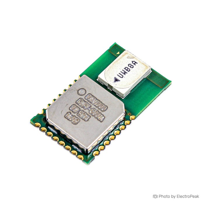
DECAWAVE DWM1000 Transceiver Module Positioning
$27.5000
In stock
SKU
SEN-15-011
Volume discounts:
- +10 3 % $26.8000
- +25 4 % $26.4500
- +50 5 % $26.1000
- +100 6 % $25.7500
- +300 8 % $25.4000
Add an Accessory:


Ships in 2-3 business days, then:
Free delivery in 12-15 days by Tracked Economic Shipping on orders over $100.
Free delivery in 7-10 days by Express Shipping on orders over $300.
More shipping info

Shop with confidence Learn More
 GY-NEO-6M V2 Flight Control GPS Module Previous
DWM1000 UWB Module Review: Before You Buy
The Decawave DWM1000 Transceiver Module Positioning is a compact UWB wireless transceiver module built around the DW1000 IC. It is designed for real-time location systems (RTLS) and wireless sensor networks, providing high-precision time-of-flight ranging through two-way ranging (TWR) or time-difference-of-arrival (TDoA) architectures. The module communicates over a host SPI bus and operates strictly within a 2.8V to 3.6V supply range.
This module is suited to engineers building custom embedded tracking nodes on dedicated 3.3V PCBs. It is not a turnkey consumer tracker: it has no onboard application microcontroller or USB port, does not output pre-calculated NMEA coordinates, and cannot plug directly into standard breadboards. Working distance or position data requires external controller firmware, multiple coordinated nodes, antenna-delay calibration, and careful RF layout.
Specifications of DECAWAVE DWM1000 Transceiver Module Positioning
- Input Voltage: 2.8V ~ 3.6V
- Frequency: 3.5GHz ~ 6.5GHz
- Channel Bandwidth: 500 MHz
- Operating Temperature: -40 to 85°C
- Location Accuracy: 10 cm
- Communication Distance: Up to 300 m
- Data Transfer Rate: Up to 6.8 Mbps
- Modulation: BPM, BPSK
- TX Mode Current: 31 mA
- RX Mode Current: 64 mA
- Interface: SPI
- Size: 23 mm x 13 mm x 2.9 mm
For custom hardware development, an external host MCU such as the ESP32-S3 WROOM-1 Development Board provides the required processing overhead and native 3.3V SPI connectivity. For alternative tracking methods, browse our broader GPS and location hardware category.
DWM1000 UWB Module Specifications Explained
Integrating a high-bandwidth radio module means matching your power rail, digital bus, and RF layout to its operating limits. These published specifications translate directly into constraints for the host PCB.
| Specification | Listed Value | Why It Matters for Integration |
|---|---|---|
| Input Voltage | 2.8V ~ 3.6V | Requires a clean, well-regulated 3.3V rail. Direct 5V logic or unregulated supplies will permanently damage the radio. |
| Interface | SPI | Operates purely as a peripheral transceiver. An external host MCU must drive all radio state transitions, framing, timestamp retrieval, and packet handling. |
| Frequency | 3.5GHz ~ 6.5GHz | Indicates supported ultra-wideband operating bands/channels within this spectrum, not a continuously tunable general-purpose RF frequency synthesizer. |
| Channel Bandwidth | 500 MHz | Wide channel bandwidth enables nanosecond-level pulse timing for precise time-of-flight measurements rather than operation as a standard Wi-Fi or Bluetooth data link. |
| Data Transfer Rate | Up to 6.8 Mbps | High payload throughput allows rapid exchange of multi-node ranging timestamps, minimizing airtime and channel congestion in dense anchor networks. |
| Modulation | BPM, BPSK | Burst Position Modulation combined with Binary Phase Shift Keying provides the pulse-based RF structure defined by the IEEE 802.15.4-2011 standard. |
| Dimensions | 23 mm x 13 mm x 2.9 mm | Small surface-mount footprint with castellated edge pads for automated SMD assembly or carrier PCBs; it is not suitable for standard 0.1-inch jumper wire use. |
| Operating Temperature | -40 to 85°C | Standard industrial rating suited to factory-floor tracking and outdoor sensor enclosures, provided the housing does not induce thermal throttling or RF detuning. |
For installation requirements beyond local ultra-wideband positioning, see our GPS and location hardware category for outdoor navigation options.
DWM1000 UWB Accuracy, Range, and Limitations
The module lists a location accuracy of 10 cm and a communication distance of up to 300 m. These figures reflect proven radio capabilities under optimized test conditions, but deployed-system performance depends entirely on physical layout, RF conditions, and calibration.
A single DWM1000 module measures time intervals only; it cannot output a standalone 2D or 3D coordinate. Accurate positions require a network of fixed anchors communicating with moving tags. The 10 cm accuracy specification relies on direct line-of-sight (LOS) conditions, good geometric dilution of precision (GDOP) across anchor placements, and systematic antenna-delay calibration. In non-line-of-sight (NLOS) environments—where signals pass through walls, human bodies, or warehouse racking—pulse arrival times are delayed. This significantly degrades ranging accuracy.
The 300 m maximum distance likewise represents an open-field, clear line-of-sight radio link at optimal data rates. Inside buildings, concrete partitions and heavy metallic structures attenuate UWB pulses and create multipath interference, effectively reducing real-world anchor-spacing requirements. For code implementation and hardware-wiring background, refer to our DWM1000 Arduino interfacing guide.
Power budgeting also needs attention. The specifications list a TX Mode current of 31 mA and an RX Mode current of 64 mA. These figures reflect baseline operating states under specific transmission powers and data rates. Peak currents can vary with packet frequency, transmit-power configuration, and receiver listen duty cycles. Do not size regulators solely from baseline values without profiling your specific transmission scheme.
Integrators should also note that a bare component module is not a certified commercial consumer product. End products must comply with regional spectrum emissions regulations according to the chosen channel, enclosure, and antenna configuration. For developers seeking an all-in-one hardware package with an onboard microcontroller and factory RTLS firmware, an MCU-integrated DWM1001-family UWB module represents a distinct architecture. The DWM1000 remains a dedicated host-controlled SPI transceiver.
DWM1000 UWB Module Compatibility and Setup Requirements
Deploying the DWM1000 requires an appropriate host controller, interface logic, and physical mounting arrangement. The module provides raw radio functionality, while the host manages the UWB MAC layer and localization math.
A functional two-way ranging verification needs at least two modules: one acting as an initiator (tag) and one as a responder (anchor). A full 2D localization layout generally needs a minimum of three fixed anchors plus tags. For 3D positioning, use four or more anchors positioned across varying vertical planes.
| System Area | Requirement | Integration Details |
|---|---|---|
| Host Controller | Required (External) | Needs an external SPI microcontroller such as STM32 or ESP32 to run the driver library, manage state machines, and parse timestamps. |
| Logic & Supply Voltage | 2.8V ~ 3.6V | A 3.3V-class host MCU is directly compatible. 5V boards (like Arduino Uno) must use active level shifters on SPI and control lines. |
| Control Lines | IRQ & RESET Required | Along with MOSI, MISO, SCK, and CS, the module requires a dedicated hardware interrupt (IRQ) and Reset pin connected to the host MCU. |
| SPI Clock Speed | Staged initialization | Initial configuration and OTP memory reads require SPI speeds below 3 MHz. Higher clock rates (up to 20 MHz) can only be engaged after the internal PLL locks. |
| Physical Mounting | Custom PCB or Carrier | The 23 mm x 13 mm castellated surface-mount package cannot be inserted directly into standard solderless breadboards. |
Another DW1000-family SPI module listing is the Anxinke BU01 DW1000 Module. It has the same core DW1000-family radio architecture, voltage limits, and external host-controller requirements.
For controller selection, the ESP32-S3 WROOM-1 Development Board provides native 3.3V logic, sufficient RAM for positioning algorithms, and integrated Wi-Fi for forwarding location data to a central server. Before finalizing a custom PCB, you can mount the module on a suitable third-party adapter and use an 830 points breadboard with a breadboard jumper wire kit for signal routing.
DWM1000 UWB Module Quick Start Check
Before assembling multi-anchor RTLS software, use this hardware verification procedure to confirm SPI communication, register access, and basic two-node ranging functionality.
- Mount the hardware: Solder the DWM1000 to a carrier board or custom breakout with clean trace routing, keeping the onboard chip antenna clear of copper ground planes.
- Establish connections: Connect the 3.3V power supply, Ground, SPI lines (SCK, MOSI, MISO, CS), the IRQ line to an interrupt-capable GPIO, and the Reset pin to your 3.3V host MCU.
- Load verification firmware: Use a maintained DW1000 driver library for your host environment, referring to our DWM1000 Arduino interfacing guide for baseline configuration.
- Verify SPI read: Initialize the SPI bus at 2 MHz or lower. Query the device ID register (address 0x00). The module should return
0xDECA0130, confirming SPI bus communication and power stability. - Configure two-node TWR: Flash one node as an initiator and a second node as a responder. Place both devices at a measured line-of-sight distance (e.g., 2.00 meters).
- Calibrate antenna delay: Record the uncalibrated range reading over multiple packets. Adjust the transmission and reception antenna-delay values in the host firmware until the reported distance matches the measured physical distance.
Common setup failures include powering or communicating with 5V logic without shifters, attempting to range with only one module, failing to wire the external IRQ line, initializing SPI above 3 MHz before PLL startup, and omitting antenna-delay calibration.
DWM1000 Alternatives for Indoor and Outdoor Positioning
The right positioning module depends on your operating environment, required accuracy, and hardware-integration scope. UWB supports high-precision local indoor ranging, while satellite GNSS modules serve wide-area outdoor navigation.
For an equivalent DW1000 hardware package, the Anxinke BU01 DW1000 Module is an exact-tier alternative based on the same Decawave DW1000 radio IC. It requires the same SPI interface and 2.8V to 3.6V design considerations.
The unlinked DWM1001-family module takes a different approach for buyers weighing development complexity. It incorporates an internal Nordic nRF52832 MCU, preloaded firmware, and BLE capabilities on the same board, whereas the DWM1000 is strictly a radio transceiver requiring external processing for all protocol tasks.
For outdoor asset tracking with unobstructed line-of-sight to the sky, satellite navigation replaces local anchor infrastructure. The GY-NEO-6M V2 GPS Module provides standard outdoor satellite navigation through a straightforward 4-pin UART output, making it suited to drones and ground rovers. In space-constrained designs requiring multiple satellite constellations, the NEO-M8N-0-10 GPS Module offers a compact GNSS receiver module with multi-interface options (UART, SPI, I2C, USB). For rapid data logging with a PC or simple microcontrollers, the Goouuu GT-U7 GPS Module provides an accessible breakout board with micro-USB connectivity and 1 to 2.5-meter outdoor tracking accuracy.
View all radio and satellite-navigation components in our complete GPS and location hardware category.
DWM1000 UWB Module FAQ
Does this DWM1000 module directly output GPS-style coordinates?
No. The module does not output coordinates, NMEA strings, or direct location data. It is an SPI-controlled radio transceiver that provides raw timestamps and packet handling for distance calculation. Producing 2D or 3D positions requires host firmware to collect range data across multiple anchor nodes and compute trilateration math. If you need standard satellite coordinates, consider an outdoor receiver such as the GY-NEO-6M V2 GPS Module.
How many DWM1000 modules do I need?
You need at least two modules for basic two-way ranging tests between an initiator and responder. A true real-time indoor location system requires additional hardware: a minimum of three anchors plus one tag for 2D positioning, or four anchors plus one tag for 3D tracking.
Will this DWM1000 module work with ESP32?
Yes, the DWM1000 interfaces effectively with ESP32 microcontrollers. ESP32 boards use 3.3V logic, so their GPIOs and hardware SPI buses interface directly with the module without logic level shifters. An external SPI host MCU such as the ESP32-S3 WROOM-1 Development Board provides the processing overhead needed to handle UWB interrupt events and ranging math.
Can I connect this DWM1000 module directly to an Arduino Uno or Nano?
No. Do not connect the module directly to 5V Arduino boards. The DWM1000 specifies an absolute supply and logic limit of 2.8V to 3.6V, so 5V SPI and control signals risk damaging the transceiver. Standard 5V boards require active logic level shifters on all signal lines, as outlined in our DWM1000 Arduino interfacing guide.
Is 10 cm location accuracy guaranteed?
No. The 10 cm specification represents optimal line-of-sight capability under controlled conditions. Real-world accuracy depends on correct antenna-delay calibration, low anchor geometric dilution of precision, and the absence of obstructions. In non-line-of-sight conditions—such as signals travelling through walls or around dense metal objects—accuracy degrades noticeably.
Will up to 300 m work inside a building or through walls?
No. The 300 m specification is a maximum open-field line-of-sight rating. Solid indoor building materials such as concrete, structural steel, and brick attenuate UWB RF signals, substantially reducing operating distance and preventing signals from propagating reliably through dense structures.
Is this DWM1000 module breadboard-ready?
No. The module has a 23 mm x 13 mm surface-mount footprint with castellated soldering pads along its edges. It cannot be inserted into 0.1-inch breadboards without a custom adapter or carrier PCB.
Does it need antenna-delay calibration?
Yes, antenna-delay calibration is mandatory for accurate ranging. Physical traces, internal RF paths, and antenna structures introduce slight propagation delays that create fixed distance offsets. Each node in your network must be calibrated against known physical distances to achieve reliable measurement precision.
Is the module certified for my commercial product and region?
No. Integrating a bare component module does not grant automatic product certification. System designers and commercial integrators remain responsible for ensuring that the finished product, including enclosure, antenna placement, and firmware configurations, meets local RF emission standards in the target market.
What is the difference between DW1000 and DWM1000?
The DW1000 is the raw transceiver integrated circuit, while the DWM1000 is an integrated module manufactured around that chip. The DWM1000 combines the DW1000 IC with an onboard ceramic pulse antenna, crystal clock oscillator, passives, and power management on a single compact PCB.
Purchase Decision Summary
- Ideal for: Embedded hardware engineers and robotics developers building custom 3.3V PCB designs for RTLS, two-way ranging, and warehouse tracking systems who have access to SMD soldering tools and external SPI controllers.
- Maybe for: Advanced makers familiar with ESP32 or STM32 programming who can route a carrier board or adapter, validate open-source drivers, run multi-node networks, and perform manual antenna-delay calibration.
- Consider another option if: You need a direct USB plug-and-play positioning device, expect automatic GPS-style coordinates from a single board, lack an external host microcontroller, plan to connect directly to 5V Arduino pins, or need long-range outdoor tracking without local anchor infrastructure.
Buying Checklist
- Confirm that you have an external 3.3V host microcontroller with an available hardware SPI bus, hardware interrupt pin, and reset line.
- Ensure that your power supply rail provides clean, regulated 2.8V to 3.6V power.
- Verify that 5V MCU logic lines will not connect directly to the module without dedicated level shifters.
- Confirm that you have a PCB land pattern, carrier board, or surface-mount soldering capability to mount the 23 mm x 13 mm castellated module.
- Order at least two DWM1000 modules to establish your first functional two-way ranging link.
- Verify that your target deployment space provides clear line-of-sight pathways, or budget for additional anchors to offset NLOS attenuation.
- Confirm that software resources and drivers exist for your chosen MCU platform to manage low-speed SPI initialization and register sequencing.
| Interface Type | SPI |
|---|---|
| Operating Voltage (V) | 2.8V - 3.6V |
| Operating Current (mA) | 31mA, 64mA |
| Operating Temp (°C) | -40 to 85 |
| Dimensions (mm) | 23mm x 13mm x 2.9mm |
| Mounting Type | SMD (Surface Mount) |
| Antenna Connector | PCB Trace |
| Position Accuracy (m CEP) | 10 cm |
| Positioning | TDOA, Two-Way Ranging (TWR) |
| Antenna Type | Internal Antenna |
| Chipset | DW1000 |
Write Your Own Review

Please complete your information below to login.
Sign In
Create New Account