
Product added to cart

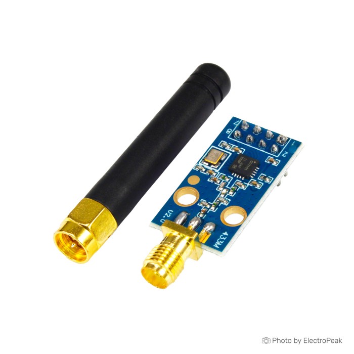
CC1101 433MHz Data Transceiver Module - Blue Borad
$2.9500
In stock
SKU
COM-09-086
Volume discounts:
- +25 4 % $2.8400
- +100 5 % $2.7900
- +300 7 % $2.7300
- +500 9 % $2.6800
- +1000 11 % $2.6200
Ships in 2-3 business days, then:
Free delivery in 12-15 days by Tracked Economic Shipping on orders over $100.
Free delivery in 7-10 days by Express Shipping on orders over $300.
More shipping info

Shop with confidence Learn More
 Si4703 Radio FM Tuner Evaluation Board Previous
CC1101 433MHz Data Transceiver Module Review
The CC1101 433MHz Data Transceiver Module is a sub-1GHz RF transceiver for low-power wireless data communication. It uses a standard 4-wire Serial Peripheral Interface (SPI), allowing microcontrollers such as the ESP32, STM32, and Arduino to configure modulation formats, transmission frequencies, and packet handling through registers. The core CC1101 architecture operates strictly between 1.8V and 3.6V, so integration demands careful logic-level planning rather than simple 5V plug-and-play connections. In the wider catalog of data telemetry modules, this board is a configurable option for point-to-point data links, sensor reporting, and legacy sub-GHz RF exploration.
Specifications of CC1101 433MHz Data Transceiver Module - Blue Borad
- Working voltage: 1.8-3.6V
- Working frequency: (module: 387-464MHZ)
- Instantaneous maximum operating current: <30mA
- Maximum transmission power: 10mW (+10dBm)
- ISM band of 315/433/868/915MHZ
- Support 2-FSK, GFSK and MSK modulation methods
- Receive sensitivity is -110dBm at 1200 baud rate
- Minimum working rate of 1.2kbps, up to 500kbps
- Separate 64-byte RX and TX data FIFO buffers
- Built-in hardware CRC error detection ensures reliable data transfer
- Support RSSI strong and weak signal detection and carrier sense function
- Low power consumption (RX, 15.6mA, 2.4kbps, 433MHz
- A suitable frequency hopping system brought by a fast frequency variation synthesizer
- The communication address (256) working frequency can be set by SPI programming
- Programmable control output power, up to +10dBm for all supported frequencies
- The WOR function can set the standby and receive state timing switching time ratio to reduce power consumption
CC1101 433MHz Specifications Explained
This module’s operating specifications balance data throughput, link budget, and host MCU overhead. Reading those ratings in circuit-design terms helps determine whether the transceiver suits your RF application.
| Specification | Rated Value | Why It Matters |
|---|---|---|
| Working Frequency | 387–464MHz | While the CC1101 chip family supports 315, 433, 868, and 915MHz bands, the RF front-end filtering and passive impedance matching on this specific module are populated for the 433MHz band (387–464MHz). Operation on 868MHz or 915MHz is severely degraded due to unmatched passive networks. |
| Data Rate Range | 1.2kbps to 500kbps | Lower baud rates such as 1.2kbps significantly improve link margin and noise rejection for distant sensors. Rates approaching 500kbps support bulk telemetry or firmware delivery, though higher data rates require wider receiver filter bandwidths and reduce effective range. |
| RF Power & Sensitivity | +10dBm TX / -110dBm RX (at 1.2kbps) | A 10mW (+10dBm) output combined with -110dBm sensitivity at 1200 baud yields an approximate link budget of 120dB under optimal conditions. That suits short-to-medium-range telemetry without external amplification. |
| 64-Byte FIFO Buffers | Separate RX & TX | Hardware FIFOs decouple RF transmission from host microcontroller timing. Packets can be queued or retrieved over SPI in bursts, freeing the host MCU from strict bit-banging or immediate real-time interrupt response. |
| Hardware CRC & Carrier Sense | Built-in | The module calculates and verifies packet checksums in hardware, dropping corrupted packets before they consume MCU cycles. Carrier sense and RSSI reporting allow basic Clear Channel Assessment (CCA) before transmitting. |
| Wake-on-Radio (WOR) | Programmable duty cycle | The internal low-power RC oscillator periodically wakes the receiver to check for incoming carrier preambles, reducing sleep current to microamp levels between polling cycles in battery-powered sensor nodes. |
CC1101 433MHz Arduino and ESP32 Compatibility
The module connects to host microcontrollers through a standard 4-wire SPI bus: MOSI, MISO, SCK, and CSN. It also needs at least one general digital output pin, GDO0. It integrates cleanly with native 3.3V microcontrollers such as the ESP32, STM32, or Raspberry Pi RP2040, while 5V architectures need special handling.
| Parameter | Requirement / State | Integration Notes |
|---|---|---|
| Supply Voltage (VCC) | 1.8V to 3.6V | A clean 3.3V rail is standard. Connecting 5V to VCC will permanently destroy the transceiver. |
| Logic Levels (SPI & GDO) | 3.3V LVCMOS | 5V microcontrollers (e.g., Arduino Uno R3, Nano) require bi-directional logic level converters or resistor divider networks on MOSI, SCK, and CSN. MISO can usually feed a 5V MCU input directly if the 3.3V logic high meets the host input threshold. |
| Interrupt Pin (GDO0) | Active High/Low selectable | Most modern CC1101 libraries require GDO0 wired to a hardware interrupt pin on the host MCU to flag packet transmission completion, sync-word detection, or FIFO fullness. |
| Supported Libraries | Community-supported | ELECHOUSE_CC1101, SmartRC-CC1101-Driver-Lib, and RadioLib provide register abstraction in Arduino IDE and PlatformIO. These libraries are third-party open-source projects and must be installed separately. |
| Shared SPI Bus | Dedicated CSN required | When sharing an SPI bus with SD card modules or SPI displays, ensure the CC1101 CSN pin is driven high when idle. Some low-cost SD modules fail to release the MISO line, preventing CC1101 initialization. |
For bench testing, flexible jumper-wire SPI connections make it easier to remap pins between the transceiver header and the microcontroller development board.
CC1101 433MHz Range, Voltage and Limitations
Operating this module means balancing safe physical wiring with realistic RF expectations. The most critical hardware constraint is input voltage: the CC1101 silicon has an absolute maximum rating of 3.9V. Unregulated 5V power or direct 5V SPI signals from an Arduino Uno will damage the chip. Power the module from a 3.3V regulator that can supply instantaneous operating currents of up to 30mA without voltage sag.
The stated communication distance of 50 to 100 meters at a 1.2k baud rate refers to open-air, line-of-sight conditions with minimal ambient RF noise. In practical deployments, 433MHz RF energy attenuates through reinforced concrete walls, human bodies, and metal enclosures. Indoor range may fall to 15–30 meters depending on structural layout and local 433MHz interference from car remotes, weather stations, and consumer alarms. This generic blue-board module also lacks factory RF calibration reports, batch traceability, and commercial regulatory certifications. Crystal tolerances can vary between batches, occasionally requiring small software frequency adjustments, such as shifting from 433.92MHz to 433.90MHz, to achieve optimal reception.
Receiver front-end saturation can occur when bench-testing two modules only a few centimeters apart. If packets fail to decode at point-blank range despite valid SPI communication, move the transmitter and receiver at least 1 to 2 meters apart or lower the programmable output power register.
Projects requiring higher RF output power or factory-calibrated extended range should consider the higher-power 433MHz transceiver option based on the Si4432, which provides up to +20dBm output. For custom RF designs where module packaging permits antenna modification, an appropriate 433MHz antenna planning component helps ensure proper impedance matching at the feed point.
CC1101 Transceiver Module vs Si4432 433MHz Transceiver
The choice between the CC1101 and the Si4432 comes down to transmit power limits, receive sensitivity, and link-budget requirements within the 433MHz spectrum.
| Feature / Specification | CC1101 433MHz Module | Si4432 433MHz Transceiver (+20dBm) |
|---|---|---|
| RF Transceiver IC | CC1101 | Silicon Labs Si4432 (B1) |
| Max Output Power | 10mW (+10dBm) | 100mW (+20dBm) |
| Receive Sensitivity | -110dBm (at 1200 baud) | -121dBm |
| Stated Range | 50–100m (at 1.2kbps) | Up to 1000m |
| Max Stated Data Rate | Up to 500kbps | 250kbps |
| Antenna Requirement | Integrated/On-board | Requires external antenna connected to ANT pad |
| Primary Trade-off | Lower power consumption, moderate range | Higher output power and sensitivity, higher current draw |
For long-distance telemetry that requires high link margins, the Si4432 433MHz Transceiver (+20dBm) offers significantly higher output power, though it requires an attached compatible external antenna for safe operation. For projects prioritizing lower current draw and standard sub-GHz packet handling within 100 meters, this CC1101 board remains the simpler design choice. An identical variant is available through the equivalent CC1101 transceiver listing.
CC1101 433MHz Setup and FAQ
A verified link needs two transceiver modules: one configured to transmit and the other to receive. Use this sequence to establish communication:
- Assemble Prototyping Hardware: Insert each module into a breadboard prototyping setup and connect the power pins to a stable 3.3V source. Ensure common ground between the MCU and the CC1101.
- Wire SPI Lines: Connect SCK, MOSI, MISO, and CSN to your microcontroller's hardware SPI bus. Connect GDO0 to a digital pin supporting external interrupts. If using a 5V Arduino, insert logic level shifters on SCK, MOSI, and CSN.
- Install Driver Library: Open your IDE, Arduino IDE or PlatformIO, and install RadioLib or SmartRC-CC1101-Driver-Lib through the library manager.
- Load Basic Code: Flash an unmodulated carrier or basic packet transmitter sketch onto Node A, then flash the matching receiver sketch onto Node B. Confirm that both sketches specify 433.92MHz, or your matching test frequency within the 387–464MHz window, and a 1.2kbps data rate.
- Verify Data Flow: Open the receiver serial monitor. You should see received packet payloads along with reported RSSI values. If packets are dropping at close range, separate the nodes by at least 2 meters.
Frequently Asked Questions
Will this CC1101 433MHz module work directly with an Arduino Uno or Nano?
No. It cannot connect directly without level shifting. The CC1101 operates strictly between 1.8V and 3.6V, so 5V power or 5V logic signals from an Arduino Uno will damage the transceiver chip.
Can this CC1101 433MHz module use 315MHz, 868MHz, or 915MHz?
No, this board is populated specifically for 387–464MHz operation. Although the core CC1101 silicon supports 315, 868, and 915MHz bands, the RF front-end inductor and capacitor networks on this PCB are tuned for 433MHz, making other bands inefficient or non-functional.
What range should I expect from the CC1101 433MHz module?
The stated range is approximately 50 to 100 meters at a 1.2kbps baud rate in an unobstructed open field. Real-world indoor range ranges from 15 to 30 meters because of walls, RF noise, and enclosure absorption.
Do I need two CC1101 modules?
Yes, for an independent transmitter/receiver link. Developing and verifying point-to-point wireless data exchange requires an active radio at both ends of the transmission path.
Why does my code report “CC1101 chip not found”?
This indicates an SPI communication failure between the host MCU and the transceiver. Check that VCC is receiving 3.3V, verify that MOSI and MISO lines are not swapped, ensure the CSN pin assignment in software matches your wiring, and confirm that common ground is connected.
Does the package include headers, a pinout guide, or a certified antenna?
No, this generic board does not include physical pinout documentation, pin headers, or certified test reports. Header pins must be sourced or soldered separately according to your project needs.
Should I choose this CC1101 board or the Si4432 module?
Choose the CC1101 for moderate range, up to 100m, with lower transmit currents (<30mA) and flexible packet features. Choose the Si4432 when you require higher transmit power (+20dBm), higher sensitivity (-121dBm), and up to 1000m range with an external antenna.
CC1101 433MHz Buying Decision
The CC1101 433MHz transceiver is a capable, register-configurable sub-GHz radio module for intermediate embedded engineers. Match its capabilities to your project requirements to avoid unexpected hardware modifications during deployment.
- Ideal for: Intermediate makers and developers building 433MHz sensor nodes, local data telemetry links, or remote-control decoders with native 3.3V microcontrollers such as the ESP32 or STM32.
- Maybe for: Arduino Uno or Nano developers who already have bi-directional logic level shifters and a dedicated 3.3V power regulator on their prototyping bench.
- Consider another option if: You require multi-kilometer battery-powered links, true plug-and-play serial operation without SPI configuration, factory regulatory certifications, or direct 5V tolerance.
For kilometer-scale data links through obstacles rather than conventional FSK telemetry, a spread-spectrum long-range LoRa IoT approach using an SX1278 transceiver is an alternative method to evaluate. For other wireless hardware options, review the full selection of data telemetry modules.
Pre-Purchase Checklist
- Confirm your project frequency falls within the module's 387–464MHz operating range.
- Verify your host microcontroller provides a hardware SPI bus and an available interrupt pin for GDO0.
- Ensure you have a 3.3V regulated power rail capable of supplying at least 30mA peak current.
- Acquire logic level converters if integrating with 5V microcontroller boards, such as Arduino Uno.
- Plan to order two units if you need to build and verify a complete two-way wireless link.
- Confirm that you are comfortable configuring third-party open-source libraries in your development environment.
| Platform | Arduino Mega, Arduino Uno, Arduino Nano, Raspberry Pi 3, Raspberry Pi 4 |
|---|---|
| Interface Type | SPI |
| Operating Voltage (V) | 1.8V - 3.6V |
| Operating Current (mA) | 15.6 mA - 30 mA |
| Operating Temp (°C) | -40 to 85 |
| Frequency Band | 433MHz, 315/433/868/915MHz |
| Data transmission rate | 1.2 kbps - 500 kbps |
| RF Modulation | GFSK |
| TX Power (dBm) | 10dBm |
| Range (m) | 100m |
| SIM Slots | 0 |
| Chipset | CC1101 |
| Modes | SRD |
| Input Voltage (V) | 1.8V - 3.6V |
| Application | ISM |
Write Your Own Review

Please complete your information below to login.
Sign In
Create New Account