
Product added to cart

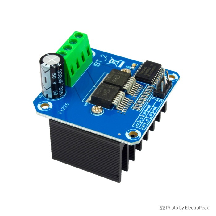
BTS7960 43A High Power Motor Driver Module
$3.2500
In stock
SKU
MTR-08-018
Volume discounts:
- +25 5 % $3.1000
- +100 7 % $3.0200
- +300 9 % $2.9500
- +500 12 % $2.8700
- +1000 14 % $2.8000
Ships in 2-3 business days, then:
Free delivery in 12-15 days by Tracked Economic Shipping on orders over $100.
Free delivery in 7-10 days by Express Shipping on orders over $300.
More shipping info

Shop with confidence Learn More
 CJMCU TB6612 DC/Stepper Motor Driver Previous
BTS7960 43A Motor Driver Review
The BTS7960 43A High Power Motor Driver Module is an H-bridge motor driver for bidirectional speed and direction control of brushed DC motors using pulse-width modulation (PWM). It operates from 5V to 27V and uses direct direction and PWM input pins, interfacing with 3.3V and 5V microcontrollers such as Arduino and ESP32 boards. Built-in functions include overcurrent protection, overtemperature shutdown, undervoltage shutdown, and current-sensing feedback.
Before designing this board into a system, account for two architectural realities. Standard boards in this family use two BTS7960 half-bridge ICs together to drive one reversible DC motor, not two independent motors. The driver silicon has a 43A internal current limit, but this generic board-level package cannot sustain 43A continuously without aggressive cooling, reinforced wiring, and controlled thermal dissipation. It suits experienced builders who can size power supplies, fuses, and thermal management for moderate-to-high-current DC actuators, winches, and robotics prototypes. Projects needing multi-motor control on one board should consider the CJMCU TB6612 I2C Driver, or browse the wider range of DC motor controllers for other setups.
Specifications of BTS7960 43A High Power Motor Driver Module
- Motor Driver Chip: BTS7960
- Operating Voltage: 5V to 27V
- Maximum Continuous Current per Channel: 43A
- Peak Current (Short Duration): Higher than the continuous current, depending on the specific model
- PWM Frequency: Up to 25 kHz
- Working Duty Cycle: 0 ~100%
- Logic Voltage: 3.3V and 5V
- Control Interface: PWM control for speed, direction control through two input pins (forward and reverse)
- Current Sensing: Includes current sensing for feedback or protection
- Over-voltage Lock Out: Included
- Under-voltage Shut Down: Included
- Standby Current: Low standby current consumption
- Dimensions (mm): 50 x 50 x 43
- Weight: ~66g
BTS7960 43A Motor Driver Specifications Explained
Putting the electrical specifications into practical engineering terms helps prevent thermal failures and control errors on the test bench.
| Specification | Value | Why It Matters in Practice |
|---|---|---|
| H-Bridge Architecture | Dual half-bridge (BTS7960 ICs) | Configured together as a full H-bridge to run a single brushed DC motor in forward, reverse, and braking modes. It cannot independently steer two separate motors. |
| Operating Voltage | 5V to 27V | Accommodates standard 12V and 24V industrial or automotive brushed motors. Operating near the lower 5V boundary requires checking that the delivered board's internal circuitry does not trigger undervoltage shutdown under load. |
| Maximum Continuous Current | 43A (chip rating) | This figure reflects the IC's internal silicon current limit, not the sustained board-level thermal limit. Real-world continuous current without forced-air cooling is substantially lower; treat sustained loads above 10A to 15A with thermal validation. |
| PWM Frequency & Duty Cycle | Up to 25 kHz, 0–100% | Allows ultrasonic switching above the 20 kHz human hearing range, eliminating motor whine during operation. Full 0 to 100% duty cycle provides complete zero-to-maximum speed range. |
| Logic Voltage | 3.3V and 5V | Directly accepts PWM and direction signals from 5V microcontrollers like an Arduino Uno. While compatible with 3.3V logic levels, reliable operation with 3.3V controllers requires verifying logic thresholds on the delivered board. |
| Current Sensing | Feedback / protection outputs | The diagnostic outputs provide an analog voltage proportional to IC current. These outputs require an external scaling resistor and microcontroller calibration; they are not direct digital current telemetry readings. |
| Protections | Overcurrent, overtemperature, UVLO, OVLO | Protects the driver IC against short-circuit and over-temperature conditions. These internal protections complement, but do not replace, an external inline fuse and system-level emergency stops. |
| Dimensions & Weight | 50 x 50 x 43 mm, ~66g | The physical height is dominated by the pre-mounted aluminum heatsink block. Enclosures must provide adequate vertical clearance and airflow around the fins. |
For smaller robotic platforms running at lower supply voltages (under 10.8V), high-current drivers of this size add unnecessary bulk. The compact DRV8833 Dual DC Driver handles dual channels up to 10.8V with switching frequencies up to 100 kHz in a fraction of the footprint.
BTS7960 Motor Driver Wiring and Compatibility
Standard BTS7960 boards, commonly called the IBT-2 layout in the maker community, use two separate half-bridge chips to create one full H-bridge. This arrangement controls one reversible brushed DC motor. A 4-wire bipolar stepper motor needs two full H-bridges, so it requires two complete modules or a dedicated stepper controller rather than one BTS7960 board.
Reliable operation depends on separate logic and motor power, with a shared reference. The high-current screw terminals provide DC motor voltage through B+ and B- and connect to the motor windings through M+ and M-. Never power the motor from the microcontroller 5V rail. The control header needs a stable 5V logic supply at VCC for the onboard isolator/buffer circuitry, plus a direct GND connection tied to the microcontroller ground.
The standard control pinout uses these signals:
- VCC: 5V logic supply.
- GND: Logic ground (must be tied to microcontroller ground).
- RPWM: Forward PWM input (drives right half-bridge high-side).
- LPWM: Reverse PWM input (drives left half-bridge high-side).
- R_EN: Forward enable input (active high).
- L_EN: Reverse enable input (active high).
- R_IS / L_IS: Current alarm and sensing outputs (optional diagnostic connections).
Verify the board on a bench before installing it in a machine with this low-risk commissioning sequence:
- Inspect the delivered module to confirm that pin and terminal labels match standard silkscreen markings.
- Connect a bench power supply or battery to B+ and B- through an inline fuse sized for testing (5A to 10A). A 12V 30A switching power supply provides stable test power for 12V systems.
- Connect an unloaded brushed DC motor to M+ and M-.
- Connect logic VCC (5V) and GND to your microcontroller, ensuring that common ground is maintained.
- Tie R_EN and L_EN high by connecting them to 5V or high digital output pins. Both half-bridges must be enabled for full H-bridge operation.
- Apply a modest PWM signal, such as 20% to 30% duty cycle, to RPWM while holding LPWM low. The motor should spin smoothly in one direction.
- Set RPWM to zero, then apply the PWM signal to LPWM. The motor should reverse direction.
If the motor does not rotate, check the basic power and control states. Confirm that the motor supply does not collapse under startup demand, both enable pins are held high, logic VCC receives 5V, and common ground between the driver and MCU remains intact. For comprehensive microcontroller code and wiring diagrams, consult the detailed Arduino BTS7960 wiring guide. For systems needing multiple motors or stepper control over a digital bus rather than discrete PWM lines, the CJMCU TB6612 I2C Driver reduces pin overhead by driving up to 4 DC motors over I2C.
BTS7960 43A Motor Driver Limitations
The headline 43A rating is the theoretical internal current limit of the BTS7960 silicon under lab conditions, not approval for 43A continuous board operation. Continuous current in practice depends on the module's thermal resistance, PCB copper thickness, screw-terminal contact resistance, and ambient airflow. Under sealed conditions without active airflow, generic modules can reach thermal limits at continuous currents between 10A and 15A. Heavy loads such as high-torque winches or DIY motion simulators can trigger internal thermal shutdown when the dissipation path is inadequate.
The board-mounted heatsink helps buffer short peak loads, but its contact with the ICs depends on thermal-pad placement in the specific production batch. In tight enclosures, forced air from a small fan or supplemental cooling with a 20x15x10mm aluminum heatsink improves thermal headroom during continuous cycling. Measure the motor stall current when sizing the system. A stalled motor immediately draws full locked-rotor current; if the supply can deliver that current and the driver cannot shed the heat, copper traces or silicon will fail.
Logic compatibility also needs attention. Although the inputs accept 3.3V logic levels, some generic board variants exhibit marginal switching when driven directly by 3.3V GPIO without a dedicated 5V VCC supply for the board's logic buffer. With an ESP32 or Raspberry Pi, power module VCC with 5V, share ground, and verify reliable switching. If the driver drops PWM pulses, add a logic-level shifter. The R_IS and L_IS pins also provide diagnostic currents that require calculation from onboard pull-down resistors to convert them into amperes; do not treat them as calibrated plug-and-play current telemetry.
Internal chip protections do not replace external safety engineering. High-inertia mechanical loads require physical limit switches and an accessible emergency power cut-off. For applications that do not need programmatic microcontroller control and only require manual potentiometer speed and direction adjustment, an enclosed standalone regulator such as the 9-55V 40A Speed Controller with Display & DIR avoids microcontroller firmware complexity entirely.
BTS7960 vs Dual Motor Drivers
Motor driver selection comes down to operating voltage, continuous current, motor-channel count, and whether control should be manual or microcontroller-driven. The table below compares the BTS7960 with alternative drivers in our catalog.
| Driver Module | Motor Voltage | Current Capacity | Motor Channels | Control Interface | Best Application |
|---|---|---|---|---|---|
| BTS7960 Module | 5V–27V | 43A peak (silicon limit); practical continuous derated | 1 DC motor (bidirectional) | GPIO / PWM (up to 25 kHz) | Single high-power 12V/24V brushed DC motor projects. |
| DRV8833 Dual DC Driver | 2.7V–10.8V | 1.5A RMS / 4A peak per channel | 2 DC motors or 1 stepper | GPIO / PWM (up to 100 kHz) | Low-voltage battery robotics and small gearmotors. |
| 7A 160W Dual Driver (L298 Replacement) | 6.5V–27V | 7A continuous / 50A peak per channel | 2 DC motors | Optocoupled PWM (up to 10 kHz) | Dual medium-power 12V/24V motors requiring optical isolation. |
| CJMCU TB6612 I2C Driver | 4.5V–13.5V | 1.2A continuous / 3A peak per bridge | Up to 4 DC motors or 2 steppers | I2C bus control | Multi-motor chassis needing minimal GPIO usage. |
| MX1508 Mini Dual Driver | 2.8V–10V | 1.5A continuous / 2.5A peak per channel | 2 DC motors or 1 stepper | GPIO / PWM (up to 1.5 kHz) | Ultra-compact, space-constrained micro-robotics. |
| 9-55V 40A Potentiometer Speed Controller | 9V–55V | 40A continuous (60A max) | 1 DC motor (unidirectional) | Manual potentiometer knob | Panel-mounted manual speed adjustment without code. |
| 9-55V 40A Speed Controller with Display & DIR | 10V–50V (9–55V) | 40A continuous (60A max) | 1 DC motor (bidirectional) | Manual knob, display & rocker switch | Bench tools, pumps, and manual actuators requiring visual duty display. |
Choose the BTS7960 when you need programmatic microcontroller speed and direction control for one high-current motor. To steer two independent 12V motors from an Arduino, use the 7A 160W Dual Driver (L298 Replacement), which provides two independent channels on one board. Its operational requirement is a 0.1-second pause before reversing direction. For other configurations, review the full catalog of DC motor controllers.
BTS7960 Motor Driver Accessories and Power Setup
High-current motor drivers need supporting power and wiring components for stable operation and bench safety.
Required Components
- Brushed DC Motor: Sized for an operating voltage between 5V and 27V, with stall currents evaluated against system capacity.
- External Motor Power Source: A high-capacity DC power supply or battery capable of delivering peak startup and stall current. For 12V bench setups, a 12V 30A switching power supply provides continuous power without the voltage sag common to small adapters.
- PWM-Capable Controller: An Arduino, ESP32, or dedicated hardware PWM generator providing direction and enable signals.
- Heavy-Gauge Power Cabling and Connectors: Stranded copper wire sized for the motor current. For high-current battery connections, an XT60 connector pair provides a low-resistance interface.
Recommended Protection & Hardware
- Inline Circuit Protection: A DC-rated fuse or circuit breaker positioned close to the power source to protect wiring against catastrophic shorts.
- Thermal Management: Forced-air cooling or a secondary 20x15x10mm aluminum heatsink for enclosed enclosures operating at high duty cycles.
- Measurement Equipment: A digital multimeter and an inline DC current clamp to record actual operating and stall currents.
- Bulk Capacitance: Low-ESR electrolytic capacitors placed across the motor power terminals to absorb inductive voltage spikes during rapid braking.
Optional Safety Hardware
- Mechanical Limit Switches: Hardwired or controller-monitored switches that halt motor movement at end-of-travel on linear actuators.
- Emergency Stop Switch: A physical latching mushroom switch wired into the motor power line to disconnect power instantly in the event of software faults.
BTS7960 Motor Driver FAQ
Can this BTS7960 module control two DC motors?
No. The module cannot independently control two DC motors because its two BTS7960 half-bridge chips form one full H-bridge for bidirectional control of one brushed DC motor. For two independent low-voltage channels, consider the MX1508 Mini Dual Driver.
Is 43A really continuous?
No, 43A is not a verified continuous board-level rating. The internal BTS7960 silicon is rated up to 43A under internal current-limiting protection, but board trace widths, terminal blocks, and heatsink dissipation limit practical continuous current to significantly lower levels unless forced-air cooling and thermal monitoring are engineered into the installation.
What motor voltage can I use?
The operating voltage range is 5V to 27V. Standard 12V and 24V brushed DC motors operate comfortably within this window. Near the lower 5V threshold, verify that voltage drops under load do not trip the board's undervoltage shutdown.
Does it work with Arduino?
Yes, the BTS7960 interfaces directly with Arduino development boards. The module accepts standard 5V logic inputs for RPWM, LPWM, R_EN, and L_EN; see the Arduino BTS7960 wiring guide for step-by-step pin connections and sample code.
Can I use an ESP32, Raspberry Pi, or another 3.3V controller?
Yes, the module lists 3.3V and 5V logic compatibility. The logic header still requires a 5V VCC supply to power the input buffers, and you must verify that your controller's 3.3V output voltage reliably meets the high-level input threshold on the delivered unit.
Why does the motor not spin?
The most common cause is disabled half-bridges. Both R_EN and L_EN must be tied to logic high (5V) for the H-bridge to function. Also confirm that motor power is present at the screw terminals, logic VCC is connected to 5V, and the microcontroller shares a common ground with the driver.
Why does the motor run in only one direction?
This occurs when only one PWM channel is active or one enable pin is low. Direction is controlled by routing PWM to RPWM (forward) or LPWM (reverse); verify that your code drives only one pin at a time while holding the other low, and ensure both enable lines remain high.
Do I need to connect R_IS and L_IS?
No, the R_IS and L_IS pins are optional diagnostic pins. They provide current feedback and fault reporting to microcontroller analog inputs. Leaving them disconnected does not impede basic motor speed and direction control.
Can one BTS7960 module run a bipolar stepper motor?
No. A single module cannot run a bipolar stepper motor. A standard 4-wire bipolar stepper motor requires two independent H-bridges to control its two phases, while this board provides only one full H-bridge. Driving a stepper requires two BTS7960 modules or a dedicated stepper driver.
Do I need a fan or additional cooling?
For intermittent or light loads below 10A, the included aluminum heatsink is generally sufficient. Sustained high-current duty cycles, continuous heavy loads, or enclosed boxes need active cooling via a fan to prevent thermal cutout.
What is included with the module?
The package contains the assembled BTS7960 driver module with its pre-attached heatsink. Power supplies, wiring, external fuses, motors, and microcontrollers must be sourced separately. For high-current battery connections, pair it with an XT60 connector pair.
Does the module require a USB, operating-system, or Arduino-library driver?
No software or operating-system drivers are needed. The BTS7960 is a hardware motor driver operated entirely through digital GPIO logic states and standard PWM signals generated by any programmable microcontroller.
BTS7960 Purchase Decision Summary
Ideal for: Experienced makers, robotics builders, and engineering students who need bidirectional PWM speed control for a single 12V or 24V brushed DC motor up to moderate currents, and who can design appropriate fusing, common grounding, and thermal management.
Maybe for: Heavy-duty prototypes such as linear actuators, electric winches, or camera dollies, provided the motor's actual stall current is measured and cooling is added if sustained loads exceed 10A to 15A.
Avoid if: You need to control two independent motors on one board, require a compact stepper motor driver, need plug-and-play operation without external wiring/fusing, or require documented, certified continuous duty near 40A.
BTS7960 Buying Checklist
- [ ] My project controls one brushed DC motor, not two independent motors.
- [ ] My motor voltage falls within the 5V to 27V operating range.
- [ ] I know my motor's locked-rotor stall current and have verified my power supply can deliver it.
- [ ] I understand that 43A is an IC silicon limit, and continuous loads require thermal validation and cooling.
- [ ] I have an inline fuse and appropriate wire gauges planned for the motor power line.
- [ ] My microcontroller has sufficient GPIO pins for two PWM channels and enable lines.
- [ ] I can supply 5V logic power (VCC) and connect common ground between the MCU and driver.
- [ ] If using a 3.3V controller (ESP32, RP2040), I am prepared to verify logic switching margins or add level shifting.
- [ ] I have planned physical safety measures (limit switches, emergency stop) for moving mechanical assemblies.
| Weight (g) | 66 |
|---|
Write Your Own Review

Please complete your information below to login.
Sign In
Create New Account