
Product added to cart

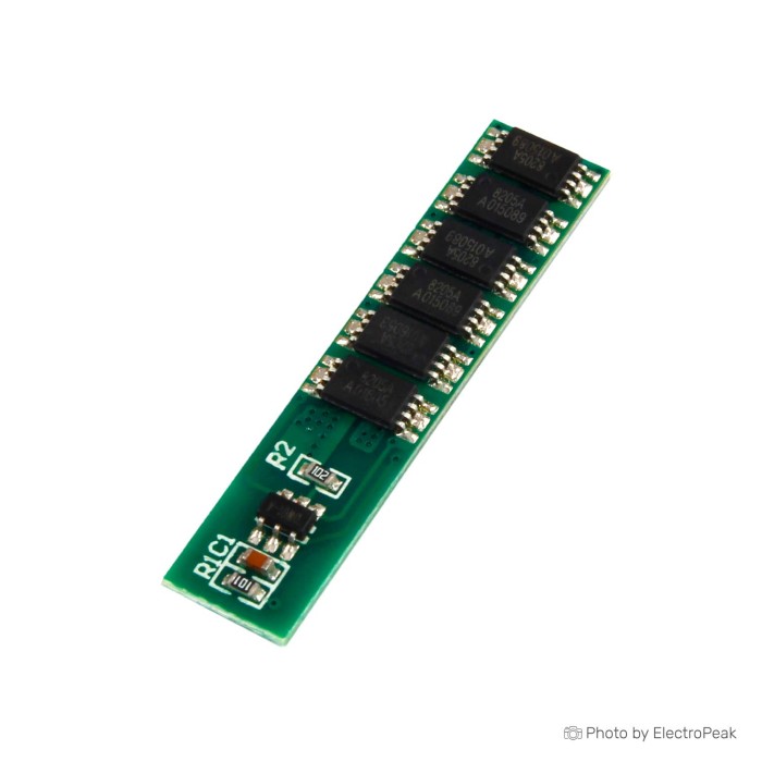
1S 3.7V 12A BMS 18650 Lithium Battery Protection Board
$0.2700
In stock
SKU
BAT-03-064
Volume discounts:
- +100 4 % $0.2600
- +500 7 % $0.2500
- +5000 11 % $0.2400
Ships in 2-3 business days, then:
Free delivery in 12-15 days by Tracked Economic Shipping on orders over $100.
Free delivery in 7-10 days by Express Shipping on orders over $300.
More shipping info

Shop with confidence Learn More
 KA2284 Power Level Indicator Module Previous
1S 3.7V 12A BMS 18650 Protection Board Review
This 1S lithium battery protection board provides essential electrical safeguards for single-cell 3.7V nominal lithium-ion and lithium-polymer setups, including standard 18650 cells. It continuously monitors the cell to protect against overcharging, over-discharging, excessive discharge current, and short circuits. With a 35x7.4x2mm footprint, it can be soldered directly onto cell terminals or installed inline with wiring in space-constrained DIY power banks, wireless sensor nodes, and small portable electronics.
Review the technical parameters before planning a build around the headline current rating. Although product titles designate this as a 12A module, the documented specifications list a sustained current of 6A and an overcurrent discharging limit of 7.5A. Design around the 6A sustained rating to avoid unexpected safety cut-offs, unless verified testing confirms higher capability in your specific thermal environment. Need a different voltage tier, series count, or form factor? Browse our broader selection of battery-management-system modules.
Specifications of 1S 3.7V 12A BMS 18650 Lithium Battery Protection Board
- Overcharge detection voltage: 4.25 + 0.05V
- Overcharge disconnection voltage: 4.23 + 0.05V
- Over-discharge voltage:2.45 + 0.1v
- Charging voltage: 4.2V
- Sustained current: 6A
- Overcurrent Discharging current: 7.5A
- Operating Temperature : -40-+85
- IC components: DW01 + 8205
- Product size: 35x7.4x2mm
1S 3.7V protection board specifications explained
Protection circuit modules work to tight electrical thresholds to safeguard lithium chemistry. Knowing how each parameter behaves through daily charging and discharge cycles helps keep the battery safe without nuisance shutdowns.
| Specification | Documented Value | Why It Matters to Your Build |
|---|---|---|
| Charging voltage | 4.2V | Matches the standard upper charging profile of a single 3.7V nominal Li-ion or LiPo cell. It confirms this board is engineered strictly for standard lithium chemistries, not 3.2V LiFePO4 cells. |
| Overcharge detection voltage | 4.25 + 0.05V | The upper safety ceiling where the control IC turns off the charging MOSFET to prevent catastrophic overcharging if a connected charger malfunctions or fails to terminate. |
| Overcharge disconnection voltage | 4.23 + 0.05V | The hysteresis recovery point. Once overcharge protection trips, battery voltage must drop back to this level before normal discharge and charge pathways re-engage. |
| Over-discharge voltage | 2.45 + 0.1v | The low-voltage shut-off point. It disables the discharge path to prevent permanent copper shunting and chemical breakdown inside an empty cell, though running cells this low regularly will shorten their working cycle life. |
| Sustained current | 6A | The primary engineering target for continuous draw. Exceeding 6A in continuous operation causes internal heating in the switching MOSFETs and risks thermal stress. |
| Overcurrent Discharging current | 7.5A | The safety trip limit. If connected loads draw 7.5A or more during discharge, the board opens the circuit to protect the wiring and battery from rapid overheating. |
| IC components | DW01 + 8205 | A common building block for single-cell protection. The DW01 monitors voltage and current sensing, while 8205 dual N-channel MOSFETs act as the electronic switches. This architecture provides protection only; it contains no charging circuitry or voltage regulation. |
| Product size | 35x7.4x2mm | The slim profile fits along the side of an 18650 cell or inside custom battery heat-shrink wraps, but the small PCB area leaves minimal copper to dissipate heat under heavier continuous loads. |
| Operating Temperature | -40-+85 | Covers typical hobbyist and field deployment environments, though the actual cell you attach will have far narrower safe operating and charging temperature limits. |
1S BMS 12A current limits and load compatibility
This board's naming can cause confusion: the title highlights 12A, while the documented continuous limit is 6A, with a 7.5A overcurrent trip threshold. In battery electronics, designing to a marketing label instead of the verified continuous figure leads to tripped loads and excessive heat. Treat 6A as the strict upper limit for sustained operation, and keep typical continuous loads around 3A to 5A for healthy thermal headroom.
Low-to-moderate-power devices run predictably on this board. Microcontroller setups, IoT sensor nodes, handheld portable gadgets, and LED strips drawing under 5A operate within the continuous rating without issue. High initial surges are a different matter. DC motors, submersible mini-pumps, inductive solenoids, and large capacitive DC-DC converters often demand three to five times their steady-state operating current during startup. Even if a small 12V boost motor draws only 2A while spinning, its locked-rotor or inrush current can spike well beyond 7.5A for tens of milliseconds and trip the overcurrent detector immediately.
Thermal management matters in compact enclosures. At 35x7.4x2mm, this board relies primarily on small surface traces and air convection to shed heat generated by the switching MOSFETs. Running near 6A continuously in an unventilated 3D-printed enclosure or inside tightly wrapped heat-shrink tubing traps heat rapidly. Leave airflow paths or integrate thermal padding when designing assemblies that operate near rated loads.
This board is purely a protective disconnect switch. It does not regulate the discharge voltage to a flat 3.7V output; your load sees the natural battery voltage swing from 4.2V when fully charged down to its cut-off threshold. It also does not charge the cell. Feed the assembly from a dedicated constant-current/constant-voltage (CC/CV) 4.2V lithium charger. For visual cell-depletion feedback during bench testing, pair the system with an optional 1S battery-level display to track state of charge.
1S 18650 BMS wiring and first test
Connecting a protection board incorrectly can damage the supervisory IC before the pack ever sees use. Because silkscreen markings vary between board revisions, inspect the physical solder pads before applying heat. Standard layouts use B+ and B- for lithium-cell connections, with P+ and P- serving as the shared charging-input and load-output terminals.
Assemble and verify your pack with these steps:
- Check cell condition: Measure your single 3.7V nominal Li-ion cell with a multimeter. It should read between 3.0V and 4.1V. Attempting to bring up a severely degraded cell resting below 2.0V can prevent the IC from turning on the MOSFET gates.
- Mount the battery: Use a dedicated enclosure or battery cradle rather than soldering directly onto raw cell terminals if you lack spot-welding equipment. A standard 18650 battery holder with lead wires works well for prototyping. For PCB-based designs, select a surface-mount 18650 holder or a through-hole 18650 holder. For a fresh power source, integrate a compatible 18650 lithium cell.
- Solder cell connections: Wire the cell positive terminal to B+ and the negative terminal to B-. Use short, adequately sized copper wire to minimize resistive losses.
- Attach load and charging lines: Connect your external 4.2V charger input and downstream DC load to P+ and P-. Ensure polarity matches your equipment exactly.
- Wake the module: Many DW01-based protection modules power up with the output MOSFETs latched in an inactive state. Connect a verified 4.2V lithium charger across P+ and P- for several seconds. This charging voltage unlocks the IC logic and activates normal output.
- Validate with a bench load: Connect a mild test load, such as a 1A power resistor or small LED array, and measure voltage across P+ and P-. The voltage should match your cell voltage minus minor MOSFET conduction drop.
Common startup failures come from reversed polarity on B+ and B-, bridge shorts across the closely spaced 35mm board pads, or attempts to power an inductive motor whose initial spike triggers the 7.5A overcurrent latch. If the board cuts off under load, disconnect the load and briefly apply a 4.2V charging input to verify recovery.
1S BMS 12A limitations: LiFePO4, motors, heat, and balancing
This module works for modest single-cell setups, but it has clear boundaries that make it unsuitable for certain battery configurations and load profiles.
- Incompatible with LiFePO4 chemistry: Lithium iron phosphate cells run at 3.2V nominal, charge to 3.65V, and damage easily if pushed beyond 3.7V. Because this board features an overcharge detection point of 4.25V and an over-discharge cutoff at 2.45V, it will severely overcharge and ruin a 3.2V LiFePO4 cell.
- No multi-cell pack support: This is an unisolated 1S circuit designed solely for one cell in series (1S). It cannot monitor multiple cells in series. If your project demands higher operating voltages, use a dedicated multi-cell board such as a two-cell series battery protection module or a three-cell battery protection with balancing module.
- No cell balancing functionality: A single-cell circuit has nothing to balance. If you parallel multiple cells into a 1S configuration (1S2P or 1S4P), the cells balance each other passively via parallel connection, but this board treats them as a single combined capacity block.
- High-inrush sensitivity: The 7.5A overcurrent trip reacts quickly to protect onboard silicon. DC power tools, high-torque gearmotors, and capacitive converter circuits routinely trip this threshold during turn-on.
- Generic module variation: This is a generic board assembly utilizing standard DW01 and 8205 components. It carries no manufacturer batch traceability, industrial certifications, or factory-calibrated current limits. Critical consumer products or safety-mandated medical devices require certified, traceable battery assemblies rather than generic protection boards.
1S vs 2S and 3S lithium protection boards
Choosing between protection boards is primarily an architecture decision based on your target voltage. Never wire multiple single-cell protection boards in series to manage a multi-cell battery pack; series strings require dedicated supervisory ICs that monitor individual node taps simultaneously.
| Module | Series Configuration | Nominal Voltage | Continuous Current | Balancing Feature | Best Application |
|---|---|---|---|---|---|
| 1S 3.7V 12A BMS | 1 cell (1S) | 3.7V | 6A sustained (7.5A overcurrent) | None (single cell only) | Single 18650 or LiPo cells for 5V boost circuits, microcontrollers, and low-draw LED devices. |
| 2S Lithium Protection Board (7.4V, 5A) | 2 cells in series (2S) | 7.4V | 3A continuous (5A instantaneous) | None | Dual-cell packs powering 7.4V audio amplifiers, robotics logic, or small 8.4V-charged electronics. |
| 3S Lithium Protection Board with Balancing (11.1V, 10A) | 3 cells in series (3S) | 11.1V | 10A continuous | Integrated balancing (up to 60mA/cell) | 12V battery replacements, field monitors, and larger multi-cell robotics projects requiring balanced cell health. |
Match the board to your battery string. A 1S setup cannot be adapted for higher-voltage series strings, and a 2S or 3S board cannot properly monitor a single 3.7V cell.
1S BMS 12A 18650 FAQ and buying checklist
Is this 12A rating continuous or peak?
The rating is an unresolved naming figure; design around the 6A sustained specification. The documented specification table explicitly lists a 6A sustained current limit and a 7.5A overcurrent discharge shut-off. Operating above 6A continuously risks tripping the module or generating excessive heat.
Can this 1S 3.7V protection board be used with a LiFePO4 3.2V cell?
No, it cannot be safely used with LiFePO4 cells. The 4.25V overcharge trip and 4.2V charging voltage are designed specifically for 3.7V nominal Li-ion and LiPo chemistries. Applying 4.2V to a 3.2V LiFePO4 battery causes severe overcharging and cell degradation.
Can this 18650 BMS run a motor or pump?
It can power small, low-power fans or motors only if their locked-rotor and startup inrush currents remain below 7.5A. Medium- or high-torque motors routinely exceed this threshold at startup, triggering immediate discharge cut-off.
Does this board charge an 18650 cell?
No, this board is an electrical safeguard, not a charger. You must provide a dedicated 4.2V CC/CV lithium-ion charging source connected across the P+ and P- terminals to recharge the cell safely.
Can I use this board for a 2S or 3S battery pack?
No. This module is engineered strictly for a 1S single-cell arrangement. Multi-cell series strings require multi-channel supervisory boards to monitor intermediate cell node voltages.
Does a 1S BMS balance cells?
No, a 1S protection circuit does not provide balancing. Cell balancing applies only to multi-cell packs wired in series, where individual cell voltages can drift apart over time.
What does the 35x7.4x2mm size mean for my build?
Its narrow form factor allows it to sit flush alongside the body of an 18650 cell under a single layer of shrink tubing. Leave adequate room for wire solder beads, terminal insulation tape, and heat dissipation if drawing continuous currents above 3A.
What should I buy with this 1S BMS?
To complete a protected battery pack, you will need a compatible 18650 lithium cell, an external 4.2V lithium charger, suitable hookup wire, and an 18650 battery holder if you want removable cells. For minimal-current designs requiring alternative form factors, explore options such as lower-current single-cell protection boards, compact low-current 1S protection boards, or 1S protection boards for lower-current portable electronics.
Can I add a battery charge meter to this board?
Yes, auxiliary display modules can be wired across the battery or output pads. Add an optional 1S battery-level display for a compact four-bar LED readout, or use an adjustable board for optional visual battery-voltage monitoring. These display modules provide visual charge status only and do not replace the electrical protection functions of the BMS board.
Purchase Decision Summary
- Ideal for: Compact single-cell 3.7V Li-ion or LiPo battery packs (such as 18650 builds) powering microcontrollers, wireless nodes, LED projects, and low-power portable gadgets with continuous current draws up to 5A or 6A.
- Maybe for: Small DC fans or mini pump applications where inrush startup surges are verified to remain below the 7.5A overcurrent cut-off limit, and where ventilation allows adequate cooling.
- Avoid if: You are using 3.2V LiFePO4 cells, building multi-cell series strings (2S, 3S, or higher), running high-inrush power tools or large motors, requiring verified continuous 12A delivery, or building commercially certified equipment needing traceable batch documentation.
Buying Checklist
- [ ] My battery pack consists of one cell in series (1S configuration).
- [ ] My cell chemistry is 3.7V nominal Li-ion or LiPo (not 3.2V LiFePO4).
- [ ] I have an external 4.2V lithium charger ready to charge the pack.
- [ ] My continuous load draw is planned around the 6A sustained current rating.
- [ ] My startup surges, capacitive inrush, and motor draws will not exceed 7.5A.
- [ ] I have allocated physical enclosure space for the 35x7.4x2mm board, wire solder joints, and insulating tape.
- [ ] I understand that this board provides safety cut-off functions and is not a voltage regulator or battery charger.
- [ ] I will inspect the physical PCB to confirm B+, B-, P+, and P- terminal markings before soldering.
| Chipset | DW01 + 8205 |
|---|---|
| Cell Count | 1 |
| Nominal Voltage (V) | 3.7V |
| Max Current (A) | 12A |
| Protection | Overcharge,Over-discharge,Over-current,Short circuit |
| Board Dimensions (mm) | 35x7.4x2 |
| Application | DIY power banks,Portable electronics,Custom lithium battery projects,IoT and smart systems |
| Operating Temp (°C) | -40 to 85 |
| Charging Voltage (Pack) | 4.2V |
Write Your Own Review

Please complete your information below to login.
Sign In
Create New Account