
Product added to cart

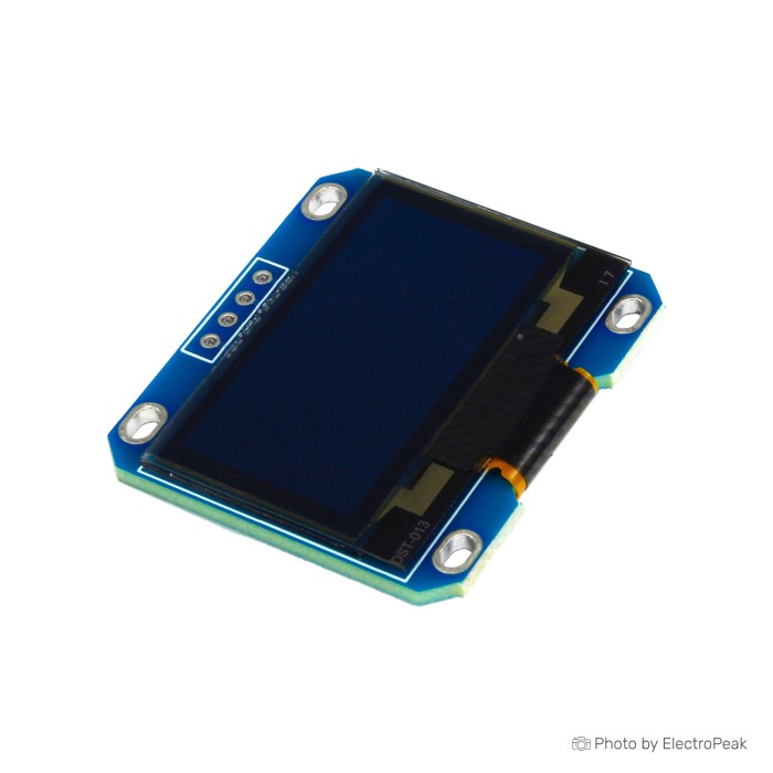
1.3inch 128x64 I2C OLED Display Module - One Color
$2.9800
In stock
SKU
LCD-01-103
Volume discounts:
- +25 4 % $2.8700
- +100 6 % $2.8100
- +300 7 % $2.7600
- +500 9 % $2.7000
- +1000 11 % $2.6500
Product Variations:


Ships in 2-3 business days, then:
Free delivery in 12-15 days by Tracked Economic Shipping on orders over $100.
Free delivery in 7-10 days by Express Shipping on orders over $300.
More shipping info

Shop with confidence Learn More
 2.42inch 128x64 I2C/SPI OLED Display Module - One Color Previous
1.3 inch I2C OLED Module Review
This 1.3-inch monochrome display module combines a 128x64 white OLED panel, an SH1106 controller, and a 4-pin I2C interface. It connects directly to microcontrollers such as Arduino, ESP8266, and ESP32 boards and operates across a specified 3.3V to 5.0V supply range. At approximately $2.95 per unit, it is a cost-effective way to add crisp graphical or text readouts to small enclosures and bench prototypes.
The main buying consideration is driver firmware. Because this board uses an SH1106 controller rather than the more common SSD1306, sketches written strictly for SSD1306 displays render text shifted horizontally by two pixels. Choosing an SH1106-specific library constructor resolves the offset immediately. It suits sensor readouts, menus, and diagnostic indicators, but not full-colour graphics, long-range viewing, or static signage where an unchanged image remains on screen indefinitely. For other panel sizes and technologies, browse our LCDs and display modules.
1.3 inch I2C OLED Specifications
Specifications of 1.3inch 128x64 I2C OLED Display Module - One Color
- Display Type: OLED (Organic Light-Emitting Diode).
- Screen Size: 1.3 inches.
- Driver IC: SH1106.
- Voltage Range: 3.3V - 5.0V.
- Resolution: 128x64 pixels.
- Display Color: White.
- Pin Number: 4 Pins for GND (power supply negative), VCC (power positive), SCL (clock line), and SDA (data cable).
- Working Temperature: -40„ to 85„.
- Dimension: 35.4mm x 33.5mm.
1.3 inch I2C OLED Specifications Explained
Evaluate this module by considering how its physical dimensions, driver architecture, and wiring requirements fit your bench build.
| Specification | Stated Value | Practical Meaning and Trade-offs |
|---|---|---|
| Screen Size & Resolution | 1.3 inches, 128x64 pixels | Provides distinct readability for four to eight lines of text, telemetry numbers, and small icons at desk distance. Characters are noticeably larger than on a 0.96-inch panel while retaining the same pixel resolution. |
| Display Type & Color | OLED, White | Each pixel emits its own light, providing true blacks, wide viewing angles, and high contrast without a separate backlight. The single-colour white output is limited to monochrome UI designs and simple data plots. |
| Driver IC | SH1106 | The internal display RAM is arranged as 132x64 bits, though only 128 columns are routed to the glass. Software drivers must apply a two-column offset so frame data begins at RAM column 2 rather than column 0. |
| Interface & Pins | 4 pins (GND, VCC, SCL, SDA) | The I2C protocol uses only two signal pins from your host controller, leaving other GPIOs available for sensors and relays. I2C refresh rates are slower than those of SPI-based panels, so it is better suited to status updates than high-framerate animations. |
| Module Dimensions | 35.4mm x 33.5mm | These figures define the outer PCB bounds, which determine enclosure bezel cutouts and clearance behind front panels. The active display area is smaller than the circuit board footprint. |
| Voltage Range | 3.3V - 5.0V | The board is specified to operate on both 3.3V logic systems such as the ESP32 and 5V microcontrollers such as traditional Arduino boards. |
For workbench prototyping, mount the board on a SYB-500 Breadboard - 200x240x8.5mm for a direct four-pin connection alongside your host MCU. Need a significantly larger monochrome screen with the same 128x64 resolution? The 2.42" 128x64 SPI/I2C OLED (SSD1309) offers a larger visual area on a 71.0mm x 43.5mm board footprint.
SH1106 1.3 inch OLED Compatibility
This module connects through four pins: ground (GND), positive supply (VCC), I2C clock (SCL), and I2C data (SDA). It works with standard I2C buses on the Arduino Uno, ESP8266, ESP32, STM32, Raspberry Pi Pico, and other supported microcontroller platforms.
| Platform / Component | Support Status | Implementation Details |
|---|---|---|
| Arduino Boards | Compatible | Connect SDA and SCL to dedicated hardware I2C pins (A4 and A5 on an Uno, or pins 20 and 21 on a Mega). Wire VCC to 5V or 3.3V. |
| ESP32 & ESP8266 | Compatible | Runs directly from 3.3V power rails. Use default I2C pins (GPIO 21/22 on standard ESP32 boards, D2/D1 on ESP8266) or assign custom pins in the Wire library. |
| Software Libraries | SH1106-specific required | Use the U8g2 library with an SH1106 constructor (e.g., U8G2_SH1106_128X64_NONAME_F_HW_I2C) or the Adafruit_SH110X library. |
| SSD1306 Existing Code | Requires constructor change | Not a drop-in software replacement. SSD1306 code displays output shifted horizontally by two pixels, cutting off the right-hand edge and leaving random noise on the left margin. |
| I2C Bus Address | Typically 0x3C or 0x3D | Generic modules in this family commonly respond to address 0x3C, though some revisions use 0x3D. Run a standard I2C scanner sketch to confirm the address before initializing your graphics library. |
| PC Drivers | None needed | The display communicates over I2C with your microcontroller firmware. No host operating system or USB driver is involved. |
With an Arduino Uno R3 (Clone), use Male/Female Jumper Wires 40 - 10/20/30 cm to connect GND to GND, VCC to 5V, SCL to A5, and SDA to A4. Step-by-step wiring and code configurations are covered in our SH1106 Arduino setup guide.
One engineering note on supply rails: although the module is rated for 3.3V to 5.0V input, component configurations can vary slightly between production batches of generic breakout boards. Inspect the voltage regulator on the back of the PCB when integrating with 5V systems. For a project that specifically requires an SSD1306 driver for legacy firmware and custom PCB integration, consider the 1.3" White OLED with 30-pin FPC (SSD1306). It runs strictly at 3.3V over a 30-pin 0.5 mm pitch flat cable.
1.3 inch OLED Display Limitations
These operating constraints matter when deciding whether this module fits the build.
- OLED Burn-in on Static Displays: Emissive OLED pixels gradually lose brightness in proportion to their on-time. Displaying static text, fixed border lines, or a non-moving dashboard continuously for months causes uneven pixel degradation (burn-in). Do not use this module for 24/7 static signage, or program a screensaver routine that inverts, shifts, or turns off the display during idle periods.
- Monochrome Output Only: The panel illuminates in white only. It cannot display colour charts, status indicator colours such as red/green indicators, or continuous-tone imagery. For applications requiring colour graphics, the 1.3" 240x240 IPS Color TFT LCD is a different approach that provides full-colour visual output via SPI.
- SH1106 Driver Mismatch: Many online Arduino tutorials default to the SSD1306 library. Uploading SSD1306 code without changing the driver selection produces an offset 2-pixel margin at the display edges. Configure the project specifically for the SH1106 controller.
- I2C Bus Throughput: Four-wire I2C keeps wiring simple, but bus speed limits overall frame rates. Rapid full-screen animations or continuous oscilloscopic waveforms appear sluggish compared with SPI-driven displays.
- Generic Board Documentation: As an unbranded breakout board, batch-specific schematics, formal EMC certifications, and precise current-draw ratings across varying pixel-fill ratios are not published. Treat it as a standard SH1106 four-pin breakout module for prototyping and small-batch builds. Browse our full selection of display modules if your design requires industrial traceability.
1.3 inch SH1106 OLED Setup Check
Use this verification sequence to test the display on arrival and confirm communication with your microcontroller:
- Wire the module: Connect GND to system ground, VCC to 3.3V or 5V, SCL to your microcontroller I2C clock pin, and SDA to the I2C data pin using Male/Female Jumper Wires 40 - 10/20/30 cm on a SYB-500 Breadboard - 200x240x8.5mm.
- Scan the I2C bus: Flash a basic I2C bus scanner sketch to your Arduino Uno R3 (Clone). Check the serial monitor to confirm that a device responds, typically at address
0x3Cor0x3D. If no device appears, check for reversed SDA and SCL leads. - Install an SH1106 library: Open the Arduino IDE Library Manager and install
U8g2by Oliver orAdafruit SH110X. - Load an SH1106 example: In the U8g2 examples, open a graphic test and uncomment the constructor
U8G2_SH1106_128X64_NONAME_F_HW_I2C u8g2(U8G2_R0, /* reset=*/ U8X8_PIN_NONE);. Ensure the I2C address matches your scanner output. - Verify display alignment: Compile and flash the sketch. Confirm that the test frames fill the entire screen horizontally without a two-pixel blank gap on the left edge.
No PC driver is required because your host development board handles all display communication directly over I2C. For complete wiring diagrams and code examples, refer to the SH1106 Arduino setup guide.
1.3 inch I2C OLED Accessories
This module is supplied as a standalone breakout board. A working prototype requires complementary hardware and software tools.
Required Accessories
- Host Microcontroller: Use an I2C-capable development board such as the Arduino Uno R3 (Clone) or an ESP32 board to generate display signals and execute firmware.
- Connection Cables: Use a set of Male/Female Jumper Wires 40 - 10/20/30 cm to bridge the module's 4-pin header to your microcontroller headers.
- SH1106 Driver Library: Install an open-source graphics library that supports SH1106 controllers, such as U8g2 or Adafruit SH110X, through your IDE's package manager.
Recommended Accessories
- Solderless Prototyping Board: A bench platform such as the SYB-500 Breadboard - 200x240x8.5mm keeps connections secure during initial testing.
- I2C Scanner Utility: Use a standard microcontroller bus scan sketch to confirm the exact hardware address before compiling custom graphics code.
- Clean Power Rail: Use a regulated 3.3V or 5V power source matched to your project’s microcontroller rail.
Optional Accessories
- Enclosure or Mounting Bezel: Use a project box sized to accommodate the 35.4mm x 33.5mm PCB footprint while exposing the 1.3-inch glass.
- I2C Pull-Up Resistors: Add external 4.7 kΩ resistors if you are running longer wiring harnesses or experiencing bus instability.
- Decoupling Capacitor: Place a 0.1 µF ceramic capacitor across VCC and GND if your power supply experiences switching ripple from nearby motors or relays.
1.3 inch I2C OLED FAQ
Will this 1.3 inch I2C OLED work with an Arduino Uno?
Yes. It connects directly using four wires: GND to GND, VCC to 5V (or 3.3V), SCL to analog pin A5, and SDA to analog pin A4. Select an SH1106 128x64 display constructor in your code rather than an SSD1306 profile.
Why is my 1.3 inch SH1106 OLED display shifted by 2 pixels?
This offset occurs when software configured for an SSD1306 controller is sent to an SH1106 screen. The SH1106 internal RAM buffer has 132 columns, while the SSD1306 has 128. Code targeted at the SSD1306 writes to memory columns 0 through 127, causing a two-pixel horizontal shift and leaving an unwritten vertical stripe on the edge. Switching to an SH1106 library constructor fixes the issue.
What I2C address does this SH1106 OLED use?
Most boards in this family respond to address 0x3C, though some variants respond to 0x3D. Because breakout boards do not always label their internal address resistor configuration, run an I2C scanner sketch first to confirm the active address on your specific unit.
Can I power this OLED display from 5V?
Yes, the module is rated for a 3.3V to 5.0V input range. When pairing it with 5V microcontrollers such as an Arduino Uno, power it directly from the 5V pin. For 3.3V microcontrollers such as the ESP32, use the 3.3V rail.
Do I need a driver on my computer?
No computer driver is required. The display communicates over an I2C bus directly with your microcontroller; your PC only needs the standard USB-to-serial driver for programming the microcontroller board itself.
Can this OLED stay on with static text all day?
It is not recommended to keep static, unchanging text on an OLED display continuously. OLED pixels degrade with active illumination time, and permanent static elements can cause burn-in over extended periods. For continuous 24/7 monitors, implement a screen blanking timer or periodically invert and shift the interface.
What is included with this OLED module?
The module is supplied as a bare breakout board featuring the display panel and a 4-pin connection header. Jumper leads, breadboards, and microcontrollers are not included and must be sourced separately.
Should I choose this 1.3 inch SH1106 OLED or a different display?
Choose this module when you need a compact, high-contrast monochrome display that uses only two microcontroller data pins. For a more compact display, consider the 0.91" 128x32 I2C OLED. For a larger physical viewing area, see the 2.42" 128x64 SPI/I2C OLED (SSD1309). Full-colour graphics call for the 1.3" 240x240 IPS Color TFT LCD. Compare additional form factors in our main LCDs and display modules category.
Purchase Decision Summary
| Fit Assessment | Project Profile |
|---|---|
| Ideal for | Microcontroller projects (Arduino, ESP32, STM32) requiring a high-contrast white monochrome display for sensor telemetry, menus, and diagnostic indicators over a 4-wire I2C bus. |
| Maybe for | Beginners and students comfortable installing an SH1106-compatible library and running an initial I2C address scan sketch. |
| Avoid if | Projects requiring colour graphics, high refresh rate animations, screens larger than 1.3 inches, continuous 24/7 static signage, or designs that require drop-in SSD1306 firmware compatibility. |
Buying Checklist
- ✓ I need a 1.3-inch monochrome white OLED display, not a colour screen.
- ✓ A 128x64 pixel resolution provides sufficient detail for my interface text and icons.
- ✓ My microcontroller has two free GPIO pins for I2C (SCL and SDA) plus 3.3V or 5V power rails.
- ✓ My enclosure can accommodate the 35.4mm x 33.5mm external PCB dimensions.
- ✓ I can use an SH1106-compatible library (such as U8g2 or Adafruit SH110X) instead of SSD1306 code.
- ✓ I am prepared to run an I2C scan sketch to confirm the module address (typically 0x3C or 0x3D).
- ✓ I have an I2C-capable microcontroller and jumper wires available for bench hookup.
- ✓ My project will not display static, unmoving graphics 24/7 without a screensaver or pixel-shift routine.
| Display Size | 1.3 inch |
|---|---|
| Display Size Range | 1 inch to 1.99 inch |
| Display Resolution | 128x64 pixels |
| Display Driver | SH1106 |
| Display Interface | I2C |
| Panle Type | PM OLED |
| Display Color Type | Monochrome |
| Touchscreen Type | None |
| Backlight Type | None |
| Viewing Angle (°) | Greater than 160° |
| Operating Temp (°C) | -40 to 85 |
| Operating Voltage (V) | 3.3V - 5.0V |
| Pins | 4 |
| Dimensions (mm) | 35.4mm x 33.5mm |
Write Your Own Review

Please complete your information below to login.
Sign In
Create New Account