
Product added to cart

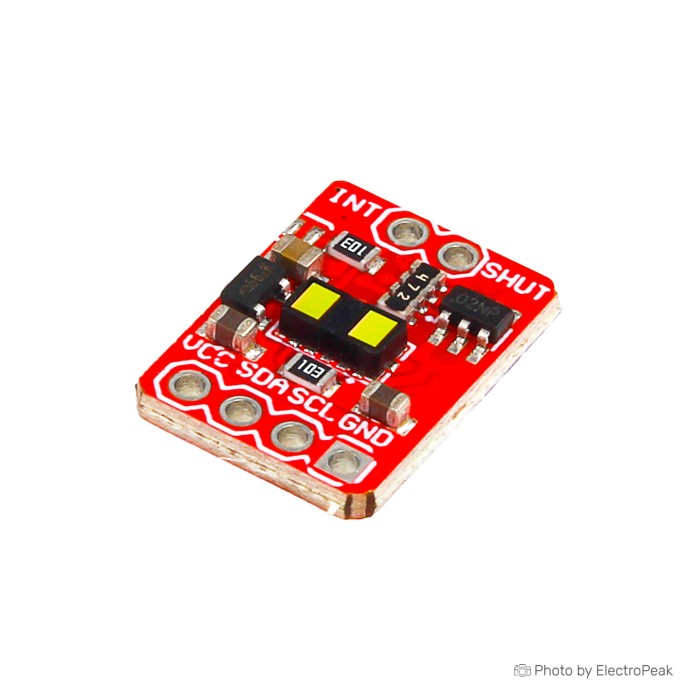
VL53L1X Laser Ranging Sensor Module
$3.5000
In stock
SKU
SEN-19-015
Volume discounts:
- +25 4 % $3.3600
- +100 6 % $3.3000
- +300 8 % $3.2300
- +500 10 % $3.1600
- +1000 12 % $3.0900
Ships in 2-3 business days, then:
Free delivery in 12-15 days by Tracked Economic Shipping on orders over $100.
Free delivery in 7-10 days by Express Shipping on orders over $300.
More shipping info

Shop with confidence Learn More
 PC817 Optocoupler Isolation Module Previous
VL53L1X Laser Ranging Sensor Review
The VL53L1X Laser Ranging Sensor Module is a compact time-of-flight (ToF) distance sensor for microcontroller projects that need reliable single-point distance measurements, threshold triggers, or user-presence detection. It communicates over I2C and offers a listed measurement span from 4 cm to 4 m, a configurable receive field of view, and dedicated shutdown and interrupt control pins. For designers comparing options across our contact and distance sensors, this board suits indoor proximity and automation tasks, but not uncalibrated outdoor use in sunlight or projects requiring documented onboard 5 V logic shifting. The equivalent VL53L1X module listing covers the same sensor configuration under an alternative listing.
Specifications of VL53L1X Laser Ranging Sensor Module
- Sensor type: Advanced time-of-flight (ToF) laser ranging sensor
- Upgrade version: VL53L0X
- Range: 4cm to 4 m
- Measurement range: Up to 4 m
- Ranging frequency: Up to 50 Hz
- Communication interface: I2C interface (up to 400 kHz)
- Voltage: 3.3-5v
- Dimension: 4.9x2.5x1.56 mm
- Weight: 10 g
- Transmitter: 940 nm invisible laser (the Class1) the SPAD (Single Photon Avalanche Diode) receive array, a lens with integrated low-power microcontroller, running the Advanced Digital firmware
- Full field of view: 27° Receiveable
- Region of Interest: Programmable Region of Interest on the Array (ROI) size allows sensor FoV to reduce the programmable ROI position on the receive array, providing host multi-zone operation control
- Control pins: Shutdown and interrupt pins
- Application: VL53L1X is used for distance measurement whatever the target color and reflectance, achieves better ant interference capability.
- VCC: 3.3V/5V power input
- GND: ground
- SDA: I2C data pin
- SCL: I2C clock pin
- SHUT: shutdown control, connects to IO pin
- INT: interrupt output, connects to IO pin
VL53L1X specifications explained
Time-of-flight technology determines distance by timing the flight duration of emitted photons rather than relying purely on reflected-light intensity. In optical distance sensing, intensity-based sensors can interpret dark objects as farther away and light objects as closer. The VL53L1X uses a 940 nm VCSEL emitter and Single Photon Avalanche Diode (SPAD) array to track photon arrival time directly. Target reflectance, surface finish, and background infrared still affect how many photons return, but calculated distance does not shift wildly with target color alone.
| Specification | Documented Value | Why It Matters |
|---|---|---|
| Operational Range | 4 cm to 4 m | Sets the operational envelope. Objects closer than 4 cm fall inside the minimum accurate distance, while the 4 m ceiling is reachable under dark indoor conditions with a highly reflective target. |
| Update Frequency | Up to 50 Hz | Provides rapid position polling for robotics or gesture tracking. This maximum frequency requires short-range timing mode; longer distance modes need wider timing windows. |
| Field of View & ROI | 27° diagonal full FoV (narrowable) | The SPAD array allows programmable Region of Interest (ROI) sizing down to 15°. Narrowing the active sensing zone helps ignore doorway frames, bin walls, or off-axis obstacles. |
| Bus Interface | I2C up to 400 kHz | Connects across standard Fast-mode I2C busses alongside other peripherals, using common two-wire signaling. |
| Control Lines | SHUT & INT pins | SHUT provides hardware standby and enables sequential address reassignment on shared busses. INT signals threshold alerts or data readiness without host polling. |
| Physical Dimensions | 4.9 x 2.5 x 1.56 mm | Reflects the surface-mount sensor package size rather than the complete carrier PCB. Allow extra clearance for headers and board routing. |
This module is a single-point distance sensor with an adjustable optical aperture, not an imaging array or scanning depth sensor. For applications needing only binary presence detection at an adjustable distance, without an I2C protocol stack, a simple digital threshold sensor supplies a direct high/low output line. For VL53L1X breadboard prototypes, flexible jumper wires for I2C wiring help maintain reliable microcontroller connections.
VL53L1X range, sunlight and limitations
The 4 m maximum range is an upper-bound measurement reached under specific operating parameters: dark ambient surroundings, a high-reflectance white target, and a long timing budget of approximately 140 ms. Change any of these variables and the effective range moves inward. Assess the relationship between light, target material, and cycle speed before deciding whether this module fits your environment.
Ambient light contains infrared energy at 940 nm, especially in direct outdoor sunlight. Strong infrared background noise saturates the SPAD array, reducing the signal-to-noise ratio and substantially shortening usable range in medium and long distance modes. In outdoor or brightly lit installations, short distance mode provides stronger ambient-light immunity, though maximum range falls to roughly 1.3 m. Dark, matte-black, or angled surfaces absorb or deflect emitted pulses, so longer timing budgets are needed to accumulate enough return photons.
Timing budget determines measurement frequency. The sensor supports update rates up to 50 Hz, but that speed applies to short-range mode with a 20 ms timing window. Maximum-distance operation needs longer integration times, typically limiting continuous measurement rates to around 30 Hz or lower. An enclosure cover introduces another consideration: plain acrylic or glass causes optical crosstalk and distance offset, so you must calibrate offset and cross-talk registers in software to maintain accurate readings. For installations that need high-power industrial buses or multi-sensor cascading over long cable runs, choose a UART/CAN cascading ranging device with dedicated processor filtering and higher baseline drive capability.
VL53L1X I2C compatibility and setup
The carrier module lists a 3.3 V to 5 V input on VCC, allowing direct power from standard development boards. The underlying VL53L1X silicon, however, requires 2.8 V to 3.3 V core logic. The exact carrier circuit, regulator dropout, and onboard logic level shifting remain unverified on generic breakout revisions, so use caution when connecting directly to 5 V microcontrollers. With 5 V boards such as the Uno, check line voltages or add dedicated bi-directional level shifting to prevent over-voltage exposure on the SDA, SCL, and control lines.
The default 7-bit I2C address is 0x29. Many technical datasheets list 0x52 for write and 0x53 for read, but these are simply 8-bit shifted representations of the same address. Standard Arduino and Linux I2C drivers use the 7-bit notation, 0x29. If your design needs verified onboard logic level shifting and built-in mounting holes out of the box, the level-shifted VL53L0X board provides a documented 5 V-safe configuration with a 2 m operational cap.
| System Domain | Implementation Details | Integration Rule |
|---|---|---|
| Host Hardware | Arduino, ESP32, Raspberry Pi, STM32 | Requires hardware I2C peripheral supporting standard 100 kHz or 400 kHz clock rates. |
| Supply Input | 3.3 V to 5 V listed | Connect common ground between sensor and microcontroller before applying bus power. |
| Logic Levels | Low-voltage sensor bus | Verify pull-up voltages; use level conversion when interfacing with unshifted 5 V host pins. |
| Default Address | 7-bit: 0x29 (8-bit: 0x52 / 0x53) | Use 0x29 in Arduino Wire and standard Linux I2C tools. |
| Bus Expansion | Dynamic software readdressing | Drive SHUT pins independently on reset to initialize sensors one by one with new addresses. |
| Driver Ecosystem | ST Ultra-Lite Driver, Pololu VL53L1X, SparkFun | Select dedicated VL53L1X libraries; VL53L0X drivers will not initialize this generation. |
For bench testing and verifying sensor response on a microcontroller, an 830-point breadboard prototype provides clean power and pull-up routing. For a complete step-by-step firmware walk-through, see our Arduino VL53L1X setup guide.
VL53L1X vs VL53L0X sensor modules
The choice between VL53L1X and older-generation VL53L0X breakout boards depends on required sensing distance, optical field narrowing, and mechanical packaging constraints. The VL53L1X doubles the listed operational distance to 4 m and adds programmable SPAD region selection. Specific VL53L0X breakout variants, however, offer distinct mechanical and electrical conveniences for shorter-range applications.
| Model | Listed Range | PCB Dimensions | Key Features |
|---|---|---|---|
| VL53L1X Module (Current) | 4 cm to 4 m | Unspecified board PCB (4.9 x 2.5 mm IC) | Up to 4 m range, up to 50 Hz, programmable ROI down to 15°, SHUT and INT pins. |
| GY-56 VL53L1X Module | 4 cm to 4 m | Unspecified board PCB (4.9 x 2.5 mm IC) | Equivalent VL53L1X module listing serving identical operational requirements. |
| GY-530 VL53L0X | 30 mm to 2 m | 10.5 x 13.3 mm | Ultra-compact footprint, 2 m ceiling, 30 mm minimum distance, standard I2C. |
| GY-53 VL53L0X | 30 mm to 2 m | 25 x 15 mm | Documented VIN-level I2C shifting, 2.8 V auxiliary regulated output, mounting holes. |
| GY-530 VL53L0X double-hole | 30 mm to 2 m | 25 x 10.7 mm | Dual mounting holes for robot chassis alignment, includes protective optical cover. |
For indoor measurements within 2 m where chassis mounting holes or physical covers matter most, the double-hole mounted VL53L0X module and the compact VL53L0X alternative fit small robot enclosures easily. For integration tutorials on the 2 m platform, see the VL53L0X Arduino setup guide. When target distances exceed 2 m or the sensor must reject nearby corridor walls through ROI cropping, the VL53L1X is the necessary choice.
VL53L1X accessories and wiring essentials
A functional VL53L1X test setup needs the required hardware, interface lines, and test components ready before assembly.
Required
- I2C-capable host controller: Use an Arduino, ESP32, Raspberry Pi, or compatible board running an I2C bus at 100 kHz or 400 kHz.
- Regulated DC power source: Provide stable 3.3 V or 5 V power and a shared common ground with the host controller.
- VL53L1X software driver: Install the official ST Ultra-Lite Driver (ULD) or a dedicated community library written specifically for the VL53L1X registers.
- Connecting wire or header pins: Use soldered header pins or flying leads to establish solid contact with the board pads.
Recommended
- Prototyping breadboard: An 830-point breadboard prototype anchors the module securely during alignment and ranging verification.
- Interconnect jumper cables: A jumper wire kit for I2C wiring routes VCC, GND, SDA, SCL, SHUT, and INT signals cleanly.
- Logic level shifter: Add a bi-directional 3.3 V to 5 V level shifter when using 5 V microcontroller platforms with pull-up voltages above 3.3 V.
- Calibration targets: Keep a flat, matte white test card and a tape measure available to confirm offset calibration and evaluate range status flags indoors.
- Optical window: Use high-transmittance thin acrylic or glass rated for 940 nm when mounting the module inside an environmental enclosure.
Optional
- Host GPIO connection for SHUT: Supports hardware shutdown for power saving and bus arbitration across multiple sensors.
- Host GPIO connection for INT: Enables event-driven threshold alerts or data-ready interrupts, freeing host processing time.
- I2C multiplexer: Simplifies hardware architecture when managing multiple distance sensors without toggling individual shutdown lines.
- Custom mechanical bracket: A laser-cut or 3D-printed fixture maintains optical alignment with your target path.
VL53L1X FAQ
Is this a real 4 m VL53L1X distance sensor?
Yes. The sensor family achieves up to 4 m under ideal operating conditions. Reaching 4 m requires long-distance mode, a high-reflectance white target, an indoor environment with low ambient infrared, and a 140 ms timing budget. Practical range is lower in bright light or on dark surfaces.
Will the VL53L1X work outdoors in sunlight?
Usable range decreases substantially in direct sunlight because of infrared saturation. Ambient 940 nm daylight noise drowns out reflected laser pulses, reducing practical distance to 1–1.5 m even in short-range mode. For extended outdoor distance monitoring, consider an active filtered sensor such as the UART/CAN cascading ranging device.
Can this VL53L1X module connect to an Arduino Uno 5 V supply?
The module lists a 3.3–5 V input on VCC, but the underlying sensor uses low-voltage logic. Because exact board-level regulator components and I2C level shifters are unverified on generic breakout revisions, an external bi-directional level shifter or a documented level-shifted VL53L0X board is safer when working with 5 V logic.
What I2C address does the VL53L1X use?
The module responds at the 7-bit address 0x29. Datasheet values 0x52 and 0x53 represent the 8-bit shifted address bytes for write and read operations. Standard Arduino Wire scripts should always address the device at 0x29.
Can I use multiple VL53L1X modules on one I2C bus?
Yes, by sequencing startup through the SHUT pin. Pull all sensor SHUT pins low to hold them in reset, bring one high, reassign its I2C address in software, and repeat for each remaining module. These software addresses persist only until power is cycled. An I2C multiplexer can also isolate identical addresses.
What is the nearest accurate distance this sensor can measure?
The minimum reliable measurement distance is 4 cm. Targets closer than 4 cm still trigger photon returns, but the internal processing cannot guarantee linear millimeter accuracy inside this near zone.
Is 1 mm accuracy guaranteed?
No. The sensor outputs data in 1 mm increments, but output resolution is not the same as absolute accuracy. Real-world accuracy depends on target reflectance, ambient infrared noise, surface angles, and timing budgets. Expect a few millimeters of variance under normal operating conditions.
Can the VL53L1X work behind glass or acrylic?
Yes, provided the material transmits 940 nm light efficiently and sits flush against the optical gasket. Any gap or refractive medium introduces optical crosstalk and offset errors, requiring you to run the ST calibration routines and store the resulting offsets in host firmware.
Do I need the SHUT and INT pins?
No. Basic distance polling uses only VCC, GND, SDA, and SCL. The SHUT pin is required for low-power sleep or dynamic readdressing of multiple sensors on one bus. The INT pin supports interrupt-driven alerts when an object enters a specific distance window.
Is the laser safe?
The sensor features a Class 1 invisible 940 nm VCSEL emitter under factory conditions and is eye-safe during standard operation. Do not add magnifying optics directly in front of the transmitter aperture or alter laser drive parameters.
For additional code samples and connection diagrams, see our Arduino VL53L1X setup guide.
Purchase Decision Summary
- Ideal for: Indoor microcontroller projects requiring millimeter-resolution distance measurements between 4 cm and 4 m, narrowable field-of-view monitoring, and low-power proximity detection on 3.3 V systems.
- Maybe for: Enclosed builds and multi-sensor arrays, provided you accommodate optical crosstalk calibration and dedicate host GPIO lines to toggle SHUT pins during startup.
- Avoid if: Your application requires guaranteed 4 m range under direct midday sun, millimeter-accurate tracking below 4 cm, scanning 3D depth maps, or verified onboard 5 V logic shifting without external components.
Buying Checklist
- Confirm your target distances fall between 4 cm and 4 m indoors.
- Verify that your target surface is non-specular and not exposed to heavy direct sunlight.
- Ensure your microcontroller provides an I2C interface running standard 100 kHz or 400 kHz speeds.
- Plan external 3.3 V / 5 V logic level conversion if interfacing with an unshifted 5 V host.
- Verify that you have spare host GPIO pins if you intend to use hardware interrupts or dynamic multi-sensor addressing.
- Confirm availability of breadboard jumper wires and headers to complete physical connections.
| Interface Type | I2C |
|---|---|
| Operating Voltage (V) | 3.3 - 5 V |
| Dimensions (mm) | 12 x 17 x 3.2 mm |
| Output Type | I2C |
| Response Time | 20 ms |
| Detection Distance | 4 cm - 4 m |
| Detection Angle (°) | 27° |
| Sensing Method | Infrared (IR) |
| Chipset | VL53L1X |
| Channels | 1-channel |
| Sensor Model | VL53L1X |
Write Your Own Review

Please complete your information below to login.
Sign In
Create New Account