
Product added to cart

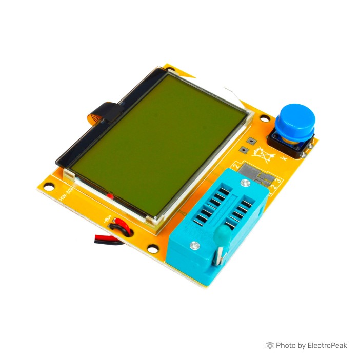
LCR-T4 Multifunction Resistor Capacitor Diode Tester
$6.5000
In stock
SKU
PRO-01-022
Volume discounts:
- +25 4 % $6.2400
- +50 6 % $6.1100
- +100 8 % $5.9800
- +300 10 % $5.8400
- +500 12 % $5.7100
Add an Accessory:

Ships in 2-3 business days, then:
Free delivery in 12-15 days by Tracked Economic Shipping on orders over $100.
Free delivery in 7-10 days by Express Shipping on orders over $300.
More shipping info

Shop with confidence Learn More
 LCR-T6 Multifunction Tester Previous
LCR-T4 Component Tester Review: What It Identifies
The LCR-T4 is a compact, standalone electronic component tester for automatic identification and quick bench checks of passive and active parts. Insert a component into the test socket and press the test button to detect common semiconductors, measure fundamental electrical parameters, and map the pin configuration on a backlit 128*64 graphic display. It is aimed at student labs, hobby workbenches, and general repair tasks that need fast sorting of unlabelled parts, salvage-component checks, and basic health confirmation. Rather than a traceable bench reference or high-precision lab bridge, the LCR-T4 is a diagnostic screening tool; technicians needing specialized bench instrumentation should consider the broader measuring equipment category for precision impedance and high-frequency testing.
Component support covers everyday discrete electronics, including NPN and PNP bipolar junction transistors, N-channel and P-channel MOSFETs, diodes and dual-diode networks, thyristors, resistors, capacitors, and inductors. The tester reads DC gain (hFE) and semiconductor forward-voltage drops while determining pin assignments on the fly, so you do not need to consult component datasheets just to identify terminal positions. At an approximate $15–25 USD typical market position across this hardware family, it is an accessible entry point for student labs, hobby workbenches, and general repair tasks, though no specific retail price is confirmed on this page.
Specifications of LCR-T4 Multifunction Resistor Capacitor Diode Tester
- Resistor measurement range: 0.1Ω-50MΩ
- Capacitor measurement range: 25PF to 100mF
- Inductance measurement range: 0.01mh to 20 H
- Resistance: ≤2100Ω
- Resistance measurement resolution: 0.1 ohm
- Maximum measurable resistance: 50 megaohm
- Test current: approximately 6 mA
- Supply mode: 6F22
- LCD size: 128*64
- LCD backlight: yes
- Dimensions: 7.2*6.25 cm
- Product name: LCR-T4 Transistor Tester
- Supply voltage: DC9V
- Work temperature: -25„~85„
- Work humidity: 5%~95%RH
- Size: 86*60.5*18.5mm
- Measure range: Resistor: 0.1ω-50Mω
- Measure range: Capacitor: 25pF-100000uF
- Measure range: Inductance: 0.01mH - 20H
- Standby current: 0.02uA
- Operating current: 25mA
LCR-T4 Specifications Explained: R, C, L and Semiconductor Results
The LCR-T4’s raw figures make more sense when you consider how a low-cost, microcontroller-based tester interacts with physical components. The table below explains what each critical specification means in day-to-day workbench use.
| Specification | Stated Value | Why It Matters in Practice |
|---|---|---|
| Resistance Range & Resolution | 0.1Ω to 50MΩ (0.1Ω resolution) | A 0.1Ω display resolution is not equivalent to 0.1Ω absolute accuracy. Contact resistance and trace impedances make uncalibrated readings below approximately 2Ω purely qualitative. Above that threshold, it reliably verifies standard pull-up, bias, and divider resistors. |
| Capacitance Range | 25pF to 100mF (100,000µF) | Small ceramic capacitors down to 25pF register quickly, but large filter capacitors demand patience. Charging large bulk electrolytics takes noticeable time, and measurement repeatability declines on very high-capacitance banks above several thousand microfarads. |
| Equivalent Series Resistance (ESR) | Capacitors ≥ 2µF | Although not stated as a headline catalog specification, this tester family provides ESR readings for capacitors of 2µF and larger. This helps weed out dried-up electrolytic capacitors without removing them to an expensive bench bridge. |
| Inductance Range | 0.01mH to 20H | Although 0.01mH (10µH) marks the bottom boundary, readings below 10–100µH are heavily influenced by lead inductance and stray coupling. Inductor testing works well for power chokes and audio filters, but RF-grade low-nanohenry coils fall outside its operating scope. |
| Semiconductor Test Current | Approximately 6 mA | A 6 mA test stimulus triggers low-power signal transistors, small MOSFET gates, and standard indicator diodes. However, power thyristors, large triacs, or high-current rectifiers requiring higher latching or gate currents may fail to trigger correctly or show false negative readings. |
| Transistor Current Gain (hFE) | Automated measurement | The reported hFE reflects low-current DC gain at the moment of test. It is useful for matching transistor pairs for audio preamplifiers or general switching checks, though it does not replace a full curve-tracer under full collector voltage and thermal load. |
| Display Assembly | 128*64 graphic LCD with backlight | The pixel display shows intuitive schematic symbols alongside numeric data, illustrating diode polarities, transistor junction layouts, and terminal pin numbers directly on screen for clear reading in dim shop environments. |
For passive chokes, capacitors, or resistors that need laboratory-style test methods, the M162 DIY LCR Meter Kit provides selectable 100Hz/1KHz test frequencies and PC serial data output as a dedicated alternative focused purely on passive impedance analysis. For loose components that cannot reach the built-in zero-insertion test socket directly, flexible Digital Multimeter Probe Test Cable leads provide a convenient connection to test points 1, 2, and 3.
LCR-T4 Calibration and Safe Use
Accurate LCR-T4 readings require systematic zero-point compensation and strict electrical safety practices. Because the instrument relies on analog comparator thresholds and precise charging ramps across its test terminals, missing basic precautions can shift values or permanently destroy the onboard controller.
Quick Calibration Procedure
- Ensure the unit is disconnected from any live circuit and powered by a fresh 9V supply.
- Insert a shorting link across the three primary test terminals—labeled TP1, TP2, and TP3—using a solid jumper wire from a Breadboard Jumper Wire Kit - 140 Pieces.
- Press the test button to initiate the self-test and zeroing routine.
- When the on-screen text prompts you to isolate the probes, remove the shorting jumper completely from the test socket.
- To complete a full-function calibration routine, insert an uncharged 220nF film capacitor across the designated pins when requested by the firmware.
This calibration zeroes internal PCB trace resistances and terminal contact offsets. It directly improves accuracy on low-resistance values and stabilizes ESR calculations on medium-sized capacitors.
Warning: Discharge all capacitors thoroughly before insertion. Connecting a charged capacitor directly to the test socket forces high voltage through the input protection network and microcontroller pins, leading to catastrophic hardware failure. Even moderate residual voltages stored in small power-supply filter caps will instantly destroy the input multiplexing circuitry. Discharge components safely using a suitable power resistor before seating them into the socket.
Electrical safety also includes static mitigation. The device operates with an active test current of approximately 6 mA across the terminals and draws around 25 mA total operating current from its 9V source. Use a stable source such as a 6F22 9V 300MAH Ni-MH Rechargeable Battery to avoid brownouts that cause the controller to abort testing prematurely.
LCR-T4 Accuracy and Limitations for Repair Work
The LCR-T4 is a useful workbench aid for fast triage, but its measurement boundaries matter when avoiding costly troubleshooting errors. It is built as a qualitative identification tool, not as an instrument certified for factory calibration or formal design verification.
Low-resistance measurements below approximately 2Ω are prone to drift. Socket oxidation, lead resistance, and internal multiplexer switches introduce errors that can equal or exceed the component value itself unless recently zeroed. For small inductors below 10–100µH, the tester struggles to calculate meaningful values because the test pulse ringing frequency is too fast for accurate capture by basic timing loops. Testing large bulk electrolytic capacitors above 4,000µF to 10,000µF also requires extended test durations, and the calculated capacitance values frequently deviate from true nominal ratings.
Semiconductor testing has defined boundaries:
- Zener Diodes: Zener breakdown identification is limited to devices operating below 4.5V. Any Zener diode with a breakdown voltage exceeding 4.5V registers as an ordinary single diode because the tester cannot generate higher reverse-bias potentials.
- Thyristors and Triacs: The internal test pulse supplies approximately 6 mA of gate current. High-power SCRs and industrial triacs with holding or triggering currents above this threshold will fail to latch, causing the tester to report an unrecognized or faulty part.
- In-Circuit Testing: The LCR-T4 is strictly intended for out-of-circuit component checks. Surrounding resistors, parallel decoupling capacitors, and semiconductor junctions in a live or assembled PCB distort test signals and prevent valid readings.
- Hardware and Firmware Variation: Units across the generic LCR-T4 ecosystem exhibit manufacturing variations. Some production batches incorporate alternative microcontrollers, such as the APT32F172, alongside standard configurations. These variants may alter display refresh behavior, contrast settings, or preclude flashing custom open-source community firmware via standard AVR programming headers.
If you need signal synthesis alongside component verification, the GM328A Component Tester with Rotary Encoder adds integrated square-wave PWM generation, a 1Hz–1MHz frequency counter, and DS18B20 digital sensor checks on a color screen. For specialized passive-component characterization where fixed AC drive frequencies matter, the M162 DIY LCR Meter Kit provides dedicated bench testing capabilities.
LCR-T4 Component Tester Compatibility and Accessories
The LCR-T4 requires a DC 9V power supply that conforms to standard 6F22 battery dimensions and snap connectors. Standard testing is entirely standalone, with no host computer connection, drivers, or configuration software required. The on-screen interface maps pins 1, 2, and 3 automatically, so you do not need to orient collector, base, or emitter leads into specific proprietary holes.
The integrated zero-insertion-force (ZIF) style socket accommodates standard through-hole leaded parts. Surface-mount devices (SMD), such as 0805 or SOT-23 packages, cannot be secured directly in the through-hole clamping contacts without an external SMD breakout board or specialized tweezer probes. Package contents are unconfirmed and do not guarantee the inclusion of batteries, test clips, or calibration parts, so suitable workbench accessories are essential alongside the tester.
| Requirement Level | Item | Purpose |
|---|---|---|
| Required | 6F22 9V 300MAH Ni-MH Rechargeable Battery | Provides the DC 9V power required to run the microcontroller, test circuitry, and LCD backlight. |
| Required | Breadboard Jumper Wire Kit - 140 Pieces | Offers short solid-core wires necessary to short test terminals TP1, TP2, and TP3 during self-calibration. |
| Recommended | 220nF Film Capacitor (Unlinked) | Required to complete the secondary stage of the full-function calibration routine. |
| Recommended | Digital Multimeter Probe Test Cable | Permits testing awkward components, bulky chassis-mount capacitors, or pre-wired assemblies off-socket. |
| Recommended | SMD Test Tweezer Probes (Unlinked) | Enables direct contact testing of surface-mount resistors, capacitors, and discrete transistors. |
| Optional | Clear Acrylic Protective Enclosure (Unlinked) | Protects the exposed underside solder joints and delicate LCD glass from bench debris and short circuits. |
For a permanent rotary encoder control dial, integrated frequency measurement, and dedicated auxiliary signal generation instead of a basic single-button layout, choose the GM328A Component Tester with Rotary Encoder as an alternative module.
LCR-T4 Component Tester FAQ
Does the LCR-T4 come with a 9V battery?
No battery is confirmed to be included with this unit. It requires a standard DC 9V supply via a 6F22 battery connector, so have a 6F22 9V 300MAH Ni-MH Rechargeable Battery ready before the board arrives.
Do I need software or drivers to use the LCR-T4 component tester?
No external software or PC drivers are needed. The tester operates as standalone test gear, running measurements and displaying output entirely on its built-in LCD screen.
How do I calibrate the LCR-T4 tester?
Short terminals TP1, TP2, and TP3 together with a wire and press the test button to run the zero-calibration routine. Remove the wire when prompted, then insert a 220nF capacitor to finish the full self-calibration sequence.
Can the LCR-T4 measure ESR on every capacitor?
No, ESR estimation is supported only on capacitors of 2µF and above. Capacitors below 2µF report capacitance values without calculating equivalent series resistance.
Is the LCR-T4 a precision LCR meter?
No, it is a fast qualitative screening tool and component identifier rather than a laboratory standard. Resistance and capacitance readings above baseline thresholds are dependable for sorting, but low-ohm and RF-range inductor tasks warrant specialized tools such as the M162 DIY LCR Meter Kit.
How accurate is the LCR-T4 for low resistance and inductance?
Measurements below roughly 2Ω and inductance readings under 10–100µH are subject to lead impedance and should be treated as qualitative estimates rather than strict figures.
Can the LCR-T4 test Zener diodes?
Only Zener diodes with a reverse breakdown rating under 4.5V can be identified. Diodes with breakdown ratings above this threshold are read as conventional single diodes.
Can I test a charged capacitor with the LCR-T4?
Never connect a charged capacitor to the tester. Stored electrostatic charge discharges straight into the microcontroller pins and permanently destroys the test port multiplexer.
Can the LCR-T4 test SMD components?
Surface-mount parts cannot be placed directly into the through-hole clamping socket without an adapter. Testing surface-mount parts requires third-party SMD test tweezers or a breakout board.
Can I flash custom firmware to this LCR-T4?
Firmware upgradability depends on the microcontroller installed on the specific board received. Manufacturing runs across this family vary and sometimes feature substitute microcontrollers, so custom firmware compatibility cannot be guaranteed.
LCR-T4 Component Tester Buying Decision
The LCR-T4 purchase decision comes down to balancing automated component triage against the need for rigorous lab measurement standards.
Purchase Decision Summary
- Ideal for: Makers, students, and technicians sorting unsorted parts drawers, verifying salvage transistors and MOSFET pinouts, checking medium-to-large filter capacitors, and screening general-purpose passives on an affordable budget.
- Maybe for: Basic workshop ESR triage on capacitors of 2µF and above, or rough potentiometer tracking, provided that borderline readings can be verified on a calibrated secondary instrument.
- Consider another option if: You require precision low-resistance measurements below 2Ω, characterization of low-value RF inductors, Zener diode identification above 4.5V, bench PC data logging, or guaranteed custom firmware flashing support.
For passive component testing with selectable AC bridge frequencies and virtual COM-port PC data recording, select the M162 DIY LCR Meter Kit. If your bench requires integrated signal synthesis, hardware frequency measurement, and temperature sensor testing, choose the GM328A Component Tester with Rotary Encoder. For broader options, browse the full measuring equipment category.
Pre-Purchase Verification Checklist
- Confirm you have a 6F22 9V 300MAH Ni-MH Rechargeable Battery or DC 9V bench clip available for power.
- Confirm that automated part identification and pinout mapping fulfill your workflow needs rather than traceable metrology.
- Have jumper wire on hand to perform the initial TP1/TP2/TP3 zeroing procedure.
- Keep a 220nF capacitor handy if you intend to run the full calibration sequence.
- Prepare a safe capacitor discharge method before connecting any power-supply capacitors.
- Ensure an external SMD adapter or tweezer probe is available if you plan to work with surface-mount parts.
Write Your Own Review

Please complete your information below to login.
Sign In
Create New Account