
Product added to cart

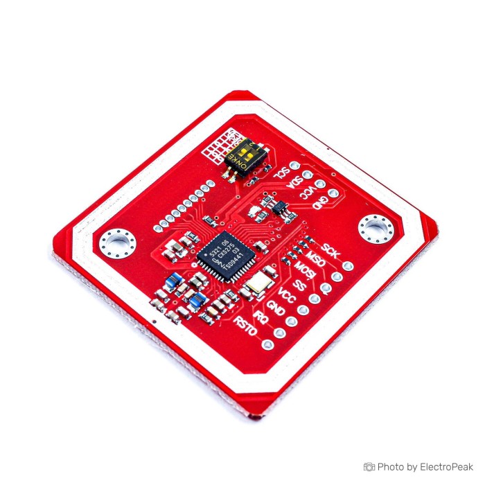
PN532 NFC/RFID Reader Writer Module - SPI/I2C Interface
$2.8500
In stock
SKU
RFID-01-002
Volume discounts:
- +25 5 % $2.7200
- +100 7 % $2.6600
- +300 9 % $2.5900
- +500 11 % $2.5300
- +1000 14 % $2.4600
Ships in 2-3 business days, then:
Free delivery in 12-15 days by Tracked Economic Shipping on orders over $100.
Free delivery in 7-10 days by Express Shipping on orders over $300.
More shipping info

Shop with confidence Learn More

PN532 NFC/RFID Reader Writer Module Overview and Specifications
The PN532 NFC/RFID Reader Writer Module is a compact 13.56 MHz high-frequency contactless communication board for embedded microcontroller and single-board computer projects. Its onboard radio controller and trace antenna support NFC or RFID reader/writer operations and peer-to-peer (P2P) data exchange. Selectable SPI, I2C, and High Speed UART (HSU) host interfaces provide flexible bus connectivity for custom prototyping. It is not intended for low-frequency 125 kHz tags or plug-and-play desktop USB card reading.
For dedicated single-board computer setups, an equivalent PN532 module for Raspberry Pi offers a direct hardware alternative designed specifically for Pi headers. For projects requiring different communication frequencies, see the options in our RFID module category.
Specifications of PN532 NFC/RFID Reader Writer Module - SPI/I2C Interface
- Communication Interfaces: I2C
- Communication Interfaces: SPI
- Communication Interfaces: HSU (High Speed UART)
- Supported Cards: Mifare 1k
- Supported Cards: Mifare 4k
- Supported Cards: Ultralight
- Supported Cards: DesFire
- Supported Cards: ISO/IEC 14443-4 cards such as CD97BX
- Supported Cards: ISO/IEC 14443-4 cards such as CD Light
- Supported Cards: ISO/IEC 14443-4 cards such as Desfire
- Supported Cards: ISO/IEC 14443-4 cards such as P5CN072 (SMX)
- Supported Cards: Innovision Jewel cards such as IRT5001
- Supported Cards: FeliCa cards such as RCS_860
- Supported Cards: FeliCa cards such as RCS_854
- Reading Distance: 5cm ~ 7cm
- Antenna: Built-in PCB antenna with a 4cm ~ 6cm communication distance
- Voltage Levels: 5V TTL for I2C and UART
- Voltage Levels: 3.3V TTL for SPI
- Mode: NFC or RFID reader/writer
PN532 NFC Module Interfaces and Compatibility
Host-interface selection depends on pin availability, communication speed, and your host controller's microarchitecture. The PN532 controller supports three hardware transport layers: SPI, I2C, and HSU. Onboard jumpers or toggle switches set the module's operating mode. Set these selector switches to match your firmware library before applying power; mismatched transport layers prevent the host from initializing communication.
Logic-level requirements vary by interface. The board specifications list 5V TTL logic levels for I2C and UART, and 3.3V TTL logic levels for SPI. When connecting 3.3V systems such as an STM32 or Raspberry Pi over UART or I2C, verify the logic levels or use inline translation if the host pins are not 5V tolerant. Secure wiring is required for a reliable host connection, and a jumper wire kit can route the connections directly.
| Interface | Listed Logic Level | Primary Advantage | Host Fit Considerations |
|---|---|---|---|
| SPI | 3.3V TTL | Fast throughput, reliable bus handling without address conflicts | Suited to high-noise environments; preferred choice for ESP32 and ESP8266 to avoid I2C clock stretching |
| I2C | 5V TTL | Low pin count (two data wires) | Standard for 5V Arduino Uno/Mega boards; can cause timeouts on ESP32 if the hardware stack poorly handles clock stretching |
| HSU (UART) | 5V TTL | Standard serial stream, minimal software overhead | Requires crossing TX and RX lines; suited to single-board computers or secondary hardware serial ports |
Software ecosystems for the PN532 are mature across multiple embedded platforms. Standard Arduino library paths, including the Adafruit PN532 library, handle SPI and I2C transactions reliably. For HSU integration, the Elechouse PN532 library provides established serial transport routines. On a Raspberry Pi or Linux SBC, ensure the selected hardware bus—SPI, I2C, or serial—is enabled in device tree configurations and that user permissions allow port access.
PN532 NFC Module Limits: Cards, Range, Android and Security
The PN532 is a versatile 13.56 MHz high-frequency device, but it is strictly incompatible with 125 kHz low-frequency cards. It cannot detect, read, or write EM4100, TK4100, or T5577 tags. For legacy building access systems using low-frequency credentials, use a dedicated 125 kHz Wiegand RFID reader or an RDM6300 125 kHz UART RFID reader. For warehouse logistics or vehicle gates requiring multi-metre tag detection, select a long-range UHF RFID reader instead.
The term "reader/writer" describes protocol capability, not universal write access. Secure, locked, or proprietary cards cannot be arbitrarily overwritten. MIFARE Classic 1K and 4K cards, for example, use sector authentication keys; without the correct key, data blocks remain inaccessible. Cards supporting ISO/IEC 14443-4 specifications, such as DESFire, require specific cryptographic handshakes and higher-level software application stacks to read or update protected memory. Checking a tag's factory UID (Unique Identifier) alone does not provide true physical access security, because many UID-changeable cards can spoof these numbers without passing cryptographic checks.
Operating range is constrained by compact magnetic induction. The stated reading distance is 5cm ~ 7cm, and the antenna communication distance is 4cm ~ 6cm. In real installations, achievable range varies with tag antenna size, spatial orientation, power supply stability, and nearby metal objects. Mounting the module behind sheet metal or heavy foil will attenuate the 13.56 MHz magnetic field entirely. Use non-metallic faceplates such as plastic, wood, or acrylic.
The module lists support for Android phone NFC interactions and P2P (peer-to-peer) communication. Exchanging data with a smartphone differs from reading a passive sticker. Mobile operating systems expect defined high-level protocols such as SNEP (Simple NDEF Exchange Protocol) operating over LLCP (Logical Link Control Protocol). Standard microcontroller sketches often lack this complete stack, so peer-to-peer mobile integration requires specialized software configuration beyond what is needed to read ordinary NDEF tags.
PN532 NFC Module Setup and First Read
Before embedding the module in an enclosure, run a basic loopback and firmware check with an Arduino or compatible microcontroller to verify hardware operation.
- Set Interface Jumpers: Configure the onboard switches or jumpers for your target interface: SPI, I2C, or HSU. Disconnect power before changing jumpers.
- Make Bus Connections: Connect power, ground, and the data lines. For HSU/UART, verify that microcontroller TX connects to module RX and microcontroller RX connects to module TX. Ensure both boards share a common ground.
- Install Library: In the Arduino IDE Library Manager, install the Adafruit PN532 library for SPI or I2C, or the Elechouse PN532 library for HSU.
- Execute Firmware Check: Open the library's basic firmware check example, such as
getFirmwareVersion. Upload the sketch, then open the Serial Monitor at the configured baud rate. - Present a Test Tag: Once the monitor prints the detected chip version, confirming host-to-module communication, swipe a known 13.56 MHz test card across the PCB antenna face. The Serial Monitor will return the UID length and hex values.
For complete pin-by-pin schematics, logic details, and sample code covering two-wire and four-wire topologies, consult our guide to interfacing the PN532 NFC RFID module with Arduino.
If the module fails during startup, check these common root causes:
- Selector mismatch: The physical DIP switches or jumpers do not match the interface defined in your code.
- UART line crossover: TX and RX pins are connected straight through rather than crossed.
- I2C bus timeout: On ESP32 systems, the I2C peripheral may hang due to clock stretching; switch to SPI or HSU to confirm hardware response.
- Tag type mismatch: An unpowered 125 kHz tag is being used instead of a 13.56 MHz high-frequency transponder.
PN532 vs RC522 RFID Modules and Other Reader Options
The choice between the PN532 and other 13.56 MHz hardware depends on interface flexibility, required card protocols, and whether you need peer-to-peer NFC operations.
| Module | Host Interfaces | Operating / Logic Voltage | Protocol & Card Highlights | Primary Use Case |
|---|---|---|---|---|
| PN532 Module | I2C, SPI, HSU (UART) | 5V TTL (I2C/UART), 3.3V TTL (SPI) | MIFARE 1K/4K, Ultralight, DESFire, ISO 14443-4, FeliCa, Jewel, P2P NFC | Versatile NFC/RFID prototyping, tag provisioning, multi-interface builds |
| RC522 SPI Module | Dedicated SPI | 3.3V operating voltage | ISO 14443A, MIFARE Classic | Low-cost, straightforward microcontroller identification and basic access control |
| RC522 TTL UART Module | Dedicated UART (115200 baud) | 5V supply | ISO 14443A, MIFARE Classic | Embedded systems requiring fixed high-speed serial tag reading without bus overhead |
| ST25R3911B NFC Dev Kit | Standalone / USB / Debug | Integrated subsystem | ISO18092, ISO14443A/B, FeliCa, ISO15693; 1.4W output power | Comprehensive lab-grade multi-protocol development with Cortex-M4F MCU and display |
The RC522 family is an accessible option when basic MIFARE Classic card reading over one dedicated interface is enough. The PN532 instead provides broader protocol support—including FeliCa, DESFire, and NFC peer-to-peer exchanges—plus multiple bus configurations on one board. For engineering setups requiring high RF output power, ISO15693 neighborhood tag support, and integrated analysis tools, the ST25R3911B development kit provides a self-contained embedded workstation.
PN532 NFC Module Accessories and Test Tags
Package contents can vary across production batches, and header pins may not be pre-soldered. Have the necessary prototyping hardware ready to build and test your circuit.
Required Accessories
- Compatible Host Controller: An Arduino, ESP32, STM32, or Raspberry Pi single-board computer with available SPI, I2C, or UART pins.
- Interface Wiring: Flexible breadboard jumper wires for stable power, ground, and communication lines.
- 13.56 MHz Test Transponder: A verified high-frequency card, such as a standard 13.56 MHz RFID IC card, to confirm initial tag detection and read functions.
- Software Library: A platform-appropriate library such as the Adafruit PN532 or Elechouse PN532 codebase.
Recommended Accessories
- Secondary Test Media: An adhesive or clear transponder, such as a transparent clear NFC tag, for validating NDEF formatting and write routines on non-card form factors.
- Logic Level Shifter: A bidirectional level translator for 5V host signals connected to sensitive 3.3V inputs when operating outside documented TTL tolerances.
- Prototyping Board & Soldering Iron: Required if pin headers must be soldered onto the module breakout pads before breadboard insertion.
Optional Accessories
- USB-to-UART Serial Converter: Useful for connecting the PN532 directly to a PC for debugging over HSU using libnfc.
- I2C Bus Multiplexer: Necessary when your architecture requires multiple PN532 readers on one shared I2C bus where address strapping is unavailable.
- Non-Metallic Project Enclosure: ABS, polycarbonate, or acrylic housing that protects the PCB antenna assembly without blocking RF signal propagation.
PN532 NFC Module FAQ and Buying Checklist
Frequently Asked Questions
Does this module read 125 kHz RFID key fobs such as EM4100 or T5577?
No. The PN532 operates exclusively at 13.56 MHz high frequency and cannot detect or read 125 kHz low-frequency transponders.
Can this reader/writer read and write MIFARE Classic 1K and 4K cards?
Yes. The module supports Mifare 1k and Mifare 4k cards. Reading and writing protected data blocks requires the correct sector authentication key in your application software.
Can this module write to any NFC or RFID card?
No. Writing requires a card that is structurally writable, unfinalized, and using an open or known security key. Proprietary, read-only, or encrypted cards, such as high-security transit credentials, cannot be arbitrarily overwritten.
Does this module work directly with Arduino?
Yes. The module is fully Arduino compatible through standard community libraries supporting SPI, I2C, or HSU.
Can I use this PN532 module with an ESP32?
Yes, but SPI or HSU (UART) is strongly recommended. The PN532 uses I2C clock stretching, which can cause bus lockups or software timeouts on certain ESP32 hardware and software configurations.
Is the module 5V logic compatible?
The module specifications list 5V TTL compatibility for I2C and UART, and 3.3V TTL compatibility for SPI. Check your pinout and verify host logic levels before making connections.
What is the maximum detection range?
The specification lists a reading distance of 5cm ~ 7cm and an antenna communication distance of 4cm ~ 6cm. Practical distance depends on tag size, relative alignment, power delivery, and enclosure composition.
Can the PN532 communicate directly with an Android smartphone?
Yes, hardware P2P and Android phone NFC support are present. Direct smartphone data exchange requires software capable of handling higher-level NFC protocols such as LLCP and SNEP.
Are jumper wires, header pins, and cards included in the package?
Package contents are not stated. Assume the module arrives as a bare board, and provide your own wiring and compatible 13.56 MHz test card to avoid setup delays.
Purchase Decision Summary
- Suited to: Makers and engineers building 13.56 MHz embedded prototypes with Arduino, Raspberry Pi, or ESP32 that require selectable SPI, I2C, or HSU communication; developers testing MIFARE Classic, Ultralight, or FeliCa tags.
- Maybe for: Android phone-to-module peer-to-peer data links, DESFire evaluation, and multi-reader environments where custom software development and bus verification can be accommodated.
- Avoid if: You must read 125 kHz tags (EM4100, T5577); you require long-range UHF asset tracking; you need an immediate plug-and-play desktop USB scanner; or you are implementing a high-security access system based solely on static tag UIDs.
Pre-Purchase Checklist
- ✓ Frequency: Verified that all tags and cards in use are 13.56 MHz, not 125 kHz.
- ✓ Card Type: Confirmed that target tags fall within listed families (Mifare 1k/4k, Ultralight, DesFire, ISO/IEC 14443-4, Jewel, FeliCa).
- ✓ Host Bus: Selected SPI, I2C, or HSU and confirmed host pin availability.
- ✓ ESP32 Architecture: Planned for SPI or HSU wiring if building on an ESP32 or ESP8266 platform.
- ✓ Logic Levels: Confirmed 3.3V TTL for SPI and 5V TTL for I2C/UART against host capabilities.
- ✓ Test Transponder: Added a verified 13.56 MHz test card or token to the order.
- ✓ Enclosure Design: Confirmed that any mounting panel surrounding the internal PCB antenna is strictly non-metallic.
- ✓ Security Scope: Designed application logic around authenticated reads rather than simple unauthenticated UID matching.
Write Your Own Review

Please complete your information below to login.
Sign In
Create New Account