Contents

Interfacing PN532 NFC RFID Module with Arduino

PN532 NFC RFID Module Features

If you are experienced in electronics, you have probably heard of RFID (radio-frequency-identification) and NFC (near-field-communication). PN532 module is a kind of RFID-NFC module that uses I2C, SPI and HSU protocols for communication. This module is based on NXP PN532 IC. The key features are:

  • Support I2C, SPI, high-speed UART (HSU) protocols
  • PCB design for antenna
  • Communication distance: 5 to 7cm
  • RFID reader and writer supports the following:
  1. Mifare 1K 4K, Ultralight and DesFire cards
  2. ISO / IEC 14443-4 cards such as CD97BX, CD light, DesFire and P5CN072 (SMX)
  3. Innovision Jewel cards such as the IRT5001 card
  4. FeliCa cards such as RCS_860 and RCS_854

You can download the datasheet of this module here.

PN532 NFC RFID Module Pinout

As mentioned above, this module supports HSU, SPI and I2C communication protocols. The module uses separate pins for SPI protocol, but the pins used for I2C and HSU communication protocols are the same. The names of the I2C pins are on the front of the module and the names of the HSU pins are on the back of the module. HSU is the default protocol of the module. You can change the communication protocol of the module to one of the I2C, SPI or HSU using DIP switches on the module.

This Module has 16 pins. The pins of each protocol are as follows:

I2C protocol:

  • VCC: Module power supply – 5V
  • GND: Ground
  • SDA: Data pin
  • SCL: Clock pin

SPI protocol:

  • VCC: Module power supply – 3-5V
  • GND: Ground
  • SCK: Clock pin
  • MISO: Output data pin
  • MOSI: Input data pin
  • SS: Slave select
  • IRQ: Interrupt pin
  • RSTO: Reset pin

HSU protocol:

  • VCC: Module power supply – 5V
  • GND: Ground
  • TXD: Transmit data pin
  • RXD: Receive data pin

You can see the pinout of this module in the image below.

Required Materials

Hardware Components

Arduino UNO R3 × 1
PN532 NFC Module × 1
Male to Female jumper wire × 1

Software Apps

Arduino IDE

Interfacing PN532 NFC RFID Module with Arduino

Step 1: Circuit

The following circuit show how you should connect Arduino to PN532 module. Connect wires accordingly.

Step 2: Library

Download the library Zip files here and here. Unzip the files and copy the folders to Arduino installation section (Libraries section).

Note

If you need more help with installing a library on Arduino, read this tutorial: How to Install an Arduino Library

Step 3: Code

Upload the following code to Arduino. After that open the Serial Monitor.

    /*
  PN532-NFC-RFID-Module-Library
  modified on 18 Nov 2020
  by Amir Mohammad Shojaee @ Electropeak
  
Home
based on www.electroschematics.com Arduino Examples */ #include <SoftwareSerial.h> #include <PN532_SWHSU.h> #include <PN532.h> SoftwareSerial SWSerial( 10, 11 ); // RX, TX PN532_SWHSU pn532swhsu( SWSerial ); PN532 nfc( pn532swhsu ); void setup(void) { Serial.begin(115200); Serial.println("Hello Maker!"); nfc.begin(); uint32_t versiondata = nfc.getFirmwareVersion(); if (! versiondata) { Serial.print("Didn't Find PN53x Module"); while (1); // Halt } // Got valid data, print it out! Serial.print("Found chip PN5"); Serial.println((versiondata>>24) & 0xFF, HEX); Serial.print("Firmware ver. "); Serial.print((versiondata>>16) & 0xFF, DEC); Serial.print('.'); Serial.println((versiondata>>8) & 0xFF, DEC); // Configure board to read RFID tags nfc.SAMConfig(); Serial.println("Waiting for an ISO14443A Card ..."); } void loop(void) { boolean success; uint8_t uid[] = { 0, 0, 0, 0, 0, 0, 0 }; // Buffer to store the returned UID uint8_t uidLength; // Length of the UID (4 or 7 bytes depending on ISO14443A card type) success = nfc.readPassiveTargetID(PN532_MIFARE_ISO14443A, &uid[0], &uidLength); if (success) { Serial.println("Found A Card!"); Serial.print("UID Length: ");Serial.print(uidLength, DEC);Serial.println(" bytes"); Serial.print("UID Value: "); for (uint8_t i=0; i < uidLength; i++) { Serial.print(" 0x");Serial.print(uid[i], HEX); } Serial.println(""); // 2 second halt delay(2000); } else { // PN532 probably timed out waiting for a card Serial.println("Timed out! Waiting for a card..."); } }

The required libraries must be included first. This code is for HSU mode. Next, 2 pins 10 and 11 are defined as serial pins in order to connect to the module. If we bring the card near to the module, it is detected and its data appears on Serial Monitor.

See the image below. Hold the card close to the module and then take it away. As you see, first the card is detected and then its data is displayed on Serial Monitor.

Liked What You See?​
Get Updates And Learn From The Best​

Comments (9)

  • RaNFC Reply

    Hello,

    is it possible to send sensor info using NFC from Arduino to mobile phone (to open web page)?

    I didn’t see anything like this..only the simple open close door etc.

    thank you in advance,
    Ran

    November 3, 2021 at 9:47 am
    • Mehran Maleki Reply

      Hi,
      No, you cannot use NFC modules to send information. They can only detect NFC cards and send the ID of the detected card to a microcontroller like an Arduino. If you want to send sensor info from Arduino to mobile, you need to use a Bluetooth module like HC-05. You can see the following tutorial for more details on you can use this module:
      https://electropeak.com/learn/interfacing-hc-05-bluetooth-wireless-module-with-arduino/
      Also for the android App, you can use “Serial Monitor Terminal”.

      November 6, 2021 at 8:18 am
  • Anders Gustavsson Reply

    Hi. I am just trying to test this board on a Arduino Uno. I have copied the code above and paste in Arduino IDE. But something seems to bee wrong. When I compile the program I get the message:

    Error compiling for board Arduino Uno.

    I have tried to find what’s wrong, but don’t find it. Please, can you help mee?

    January 6, 2022 at 1:27 pm
    • Mehran Maleki Reply

      Hi.
      It’s probably because the libraries are not properly installed. The “Library” section of the tutorial is now updated. Try the new libraries to see if it solves the issue.

      January 8, 2022 at 7:09 am
      • Johna Reply

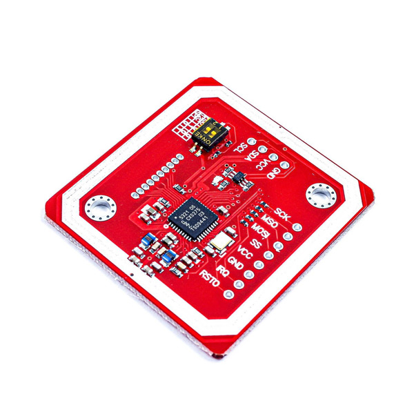
        I have a doubt: the power supply is 5V but on datasheet there is written the max voltage on I2C/SPI pins is PVDD and the max voltage on PVDD is 3.6V, so PN532 has 5V tollerant pins?

        May 6, 2022 at 3:11 pm
  • flez1966 Reply

    arduino ide stops with

    Arduino: 1.8.19 (Windows 7), Board: “ESP32 Wrover Module, Minimal SPIFFS (1.9MB APP with OTA/190KB SPIFFS), QIO, 80MHz, 921600, None”

    Alternatives for SoftwareSerial.h: []

    ResolveLibrary(SoftwareSerial.h)

    -> candidates: []

    testing_hsu:10:28: fatal error: SoftwareSerial.h: No such file or directory

    compilation terminated.

    I guess i dont have that library, and the guide doesnt say to add it, i know its common and i can add it, but thats a missing step…..

    (was tested on a fresh install)

    March 3, 2022 at 12:25 pm
    • Mehran Maleki Reply

      Hi.
      The code is only written for Arduino AVR Boards and you can’t use it for other boards like ESP32.

      March 5, 2022 at 6:01 am
  • Anthony Gabriel Leite Reply

    Is communication between two RFID modules possible? I was thinking about using one as a recorder and the other as a receiver, the reason for this idea is a way to see how bus pass chargers work, if it is possible to read the code on these RFID chargers, in other words, I would need read from another device in recording mode.

    December 25, 2023 at 1:44 am
    • Mohammad Damirchi Reply

      Hi Anthony,
      To my knowledge, it’s not possible to use two RFID readers as both a reader and a writer simultaneously.
      Additionally, this model operates within a distance of 1 to 4 cm.
      If you need to read something in passing, you might want to consider using a QR-Code scanner with a camera, such as the ESP-CAM

      December 25, 2023 at 5:45 am

Leave a Reply

Your email address will not be published. Required fields are marked *