
Product added to cart

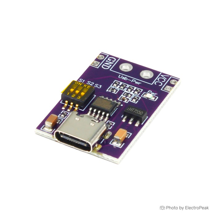
PD/QC/AFC Fast Charging Decoy Trigger Module
$0.8500
In stock
SKU
BAT-02-149
Volume discounts:
- +50 4 % $0.8200
- +100 6 % $0.8000
- +300 8 % $0.7800
- +500 11 % $0.7600
- +1000 12 % $0.7500
Ships in 2-3 business days, then:
Free delivery in 12-15 days by Tracked Economic Shipping on orders over $100.
Free delivery in 7-10 days by Express Shipping on orders over $300.
More shipping info

Shop with confidence Learn More
 Shell for XH-M229 Power Supply ATX Adapter Board Previous
PD/QC/AFC Decoy Trigger Module Review
This PD QC AFC decoy trigger module requests fixed DC voltage rails from compatible USB fast chargers and power banks. It communicates with the power source through fast-charging protocols rather than converting or stepping up power internally, outputting 5V, 9V, 12V, 15V, or 20V. It suits applications that need a selected rail from a compatible source. If you need to boost a standard 5V USB source, automatically detect the voltage required by connected electronics, or use the module without verification, choose an active converter instead.
Specifications of PD/QC/AFC Fast Charging Decoy Trigger Module
- Fast Charging Protocols: PD2.0/PD3.0, QC2.0/QC3.0, and AFC
- Voltage: Support 5V 9V 12V 15V 20V fixed voltage output(voltage step is not supported)
- Voltage Regulation: According to the table on the back of the module, adjust the dip switch to control the voltage output
PD/QC/AFC Decoy Trigger Module Specifications Explained
This fast-charging trigger acts strictly as a protocol sink, instructing the upstream supply to deliver an available fixed profile. Knowing how it negotiates power helps prevent improper hardware configurations and equipment damage.
| Specification | Technical Value | Why It Matters |
|---|---|---|
| Protocol Support | PD2.0/PD3.0, QC2.0/QC3.0, AFC | Broadens compatibility across USB Power Delivery wall warts, Quick Charge power banks, and Adaptive Fast Charging adapters, allowing you to use multiple types of existing fast-charge hardware. |
| Output Voltages | Fixed 5V, 9V, 12V, 15V, 20V | Provides common DC rails needed for bench testing, routers, development boards, and audio gear. It does not support arbitrary intermediate voltages or gradual stepping. |
| Configuration Method | Onboard DIP switches | Enables direct hardware selection without requiring microcontroller programming, software tools, or soldering bridges. |
| Voltage Adjustment Mode | Fixed profile selection | Because the module does not perform internal DC-DC conversion, it requests only standard power rails established by the connected charger. |
In practice, this module family works like generic CH224K trigger board designs, with onboard logic handling the handshakes. Common applications include powering 12V networking gear from a portable PD battery, running 15V or 20V embedded test benches, and fabricating dedicated DC power cables from USB-C power bricks.
PD/QC/AFC Decoy Trigger Module Limitations and Compatibility
The main operational boundary of any USB decoy module is simple: it cannot create voltage out of thin air. The connected charger must natively support the exact protocol and voltage profile selected on the switches. An ordinary 5V-only USB port will provide only 5V, regardless of switch position. If your source supplies only 5V and you need a higher rail, see our DC-DC regulator modules or use an integrated 5V-to-12V USB boost cable, which actively steps up 5V to 12V with an output of roughly 0.8A.
- Board specifications support up to 100W power delivery, but obtaining 20V at 5A requires a source capable of that profile and a 5A-rated E-Mark USB-C cable.
- Standard USB-C cables lack an E-Marker chip and are restricted by the USB specification to 3A, limiting 20V configurations to 60W.
- Continuous board-level thermal limits under sustained 5A loads are unverified, so high-current setups require adequate airflow and monitoring.
- This hardware family uses a USB-C male interface; micro USB connections are not supported despite ambiguous naming in generic documentation.
PD/QC/AFC Decoy Trigger Module Setup and Voltage Verification
Applying the wrong voltage can permanently damage downstream components. Follow a strict verification routine before wiring loads to the output pads.
- Disconnect the board from all power sources.
- Inspect the silk-screened configuration table on the back of the specific board you received, as DIP mapping can vary between manufacturing runs.
- Set the DIP switches to match the desired output voltage. The switch levers are small, so actuate them gently using a non-conductive fine-tip probe.
- Plug the module into a compatible USB-C PD/QC/AFC power source.
- Measure the voltage between the VCC and GND output pads using a digital multimeter.
- Only after the multimeter confirms the intended rail, disconnect the power source and connect your downstream circuit.
The board has no digital readout. For inline visibility into input-side supply parameters, an external USB power monitoring tool can show negotiated voltage and drawn current, but it does not replace checking the raw output pads with a meter.
PD/QC/AFC Decoy Trigger Module vs PD Trigger Alternatives
DC power projects call for different configuration styles, protocol support, and conversion topologies. This is how the DIP-switch trigger compares with alternative hardware options:
| Module | Type | Protocols Supported | Voltage Selection | Primary Use Case |
|---|---|---|---|---|
| PD/QC/AFC Decoy Trigger Module | Sink Trigger Board | PD2.0/PD3.0, QC2.0/QC3.0, AFC | 5V, 9V, 12V, 15V, 20V via DIP switch | Quickly switching between fixed voltages without soldering. |
| PD trigger board with PPS/QC4+/FCP support (HW-398) | Sink Trigger Board | PD3.0/2.0, PPS/QC4+, QC3.0/2.0, FCP, AFC | 9V, 12V, 15V, 20V via solder pads | Permanent single-voltage installations and sources requiring PPS or Huawei FCP. |
| 5V-to-12V USB boost cable | Active Step-Up Cable | Standard 5V USB (No PD required) | Fixed 12V barrel output (~0.8A max) | Running low-power 12V devices directly from legacy 5V USB ports. |
| Dual-port fast-charge output from a DC source | Step-Down Power Supply | QC3.0/QC2.0 step-down source | Variable fast-charge output (3V–12V) | Creating USB charging ports from an external 6V–32V battery or bench supply. |
Choose this PD QC trigger module when you need multi-rail flexibility that you can change on the fly. For a vibration-resistant configuration at one permanent voltage, the solder-jumpered HW-398 is an effective alternative.
PD/QC/AFC Decoy Trigger Module Accessories
A functional, safe setup requires several peripheral tools and connectors. They are grouped below by necessity.
Required Items
- Compatible USB-C Fast Charger or Power Bank: Must support PD2.0/3.0, QC2.0/3.0, or AFC profiles matching your intended target voltage.
- Properly Rated USB-C Cable: Standard cables suffice up to 3A (60W max at 20V); a 5A E-Mark cable is mandatory if demanding up to 100W (20V at 5A).
- Digital Multimeter: Essential for checking output voltage across the VCC and GND terminals before attaching equipment.
- Load Wiring: Wire leads soldered directly to the board output pads to route power to your project.
Recommended Items
- Soldering Equipment and Heat Shrink: Provides robust mechanical attachment and electrical insulation over exposed PCB conductors.
- DC Barrel Jack or Screw Terminal Block: Facilitates easy connection and disconnection of downstream loads.
- Airflow or Enclosure Ventilation: Recommended when operating at higher currents to manage thermal dissipation.
Optional Items
- USB power monitoring tool: Connects inline between the source and trigger module to monitor protocol negotiation and drawn power in real time.
- Project Enclosure: Protects the module PCB from accidental shorts on the workbench.
PD/QC/AFC Decoy Trigger Module FAQ and Buying Checklist
Will this PD/QC/AFC decoy trigger module give me 20V from any USB-C charger?
No. The module can request only voltage rails that the connected power supply already supports. If the charger supplies only 5V, 9V, and 12V, selecting 20V will not produce a 20V output.
Can this USB decoy module turn 5V into 12V?
No. It is not an active boost converter. To generate 12V from a conventional 5V-only USB port, use a dedicated step-up device such as the 5V-to-12V USB boost cable.
Does this module support micro USB input?
No. Despite generic catalog references, this physical board family uses a USB-C interface and does not include micro USB input hardware.
Do I need a special cable to draw 100W?
Yes. Accessing 20V at 5A (100W) requires both a 100W-capable PD supply and an electronically marked 5A USB-C cable. Standard USB-C cords max out at 3A (60W at 20V).
How do I confirm which switch setting selects which voltage?
Use the reference table printed on the underside of your specific PCB, as generic tables published online can differ across production lots. Always verify the output with a multimeter.
Why does the module output only 5V after setting the switches?
This indicates that the upstream power supply does not support the requested protocol or voltage step, causing it to default to the standard 5V USB safe state.
How does this board differ from a step-down supply module?
This module triggers voltage from a USB charger. To generate fast-charge USB ports from an external DC supply, such as a 12V car battery, use a single-port DC-powered fast-charge module instead.
Purchase Decision Summary
- Ideal for: Hobbyists, technicians, and developers needing selectable 5V, 9V, 12V, 15V, or 20V supplies from existing fast chargers without soldering configuration bridges.
- Maybe for: Testing USB-C PD power banks or replacing proprietary wall adapters for routers and small equipment when you have a multimeter to verify voltage beforehand.
- Avoid if: You need an active boost converter from 5V supplies, require fine voltage adjustment steps, lack basic soldering and testing tools, or need an onboard voltage display.
Pre-Purchase Checklist
- Confirm your USB power source explicitly lists the voltage profile (e.g., 12V, 15V, 20V) you plan to use.
- Ensure your load requires a fixed voltage matching 5V, 9V, 12V, 15V, or 20V.
- Verify that you have an E-Mark 5A cable if you plan to draw more than 3A at 20V.
- Have a digital multimeter on hand to verify pad voltage prior to powering your circuit.
- Confirm that you can solder wires or terminal hardware directly to the board's output pads.
Write Your Own Review

Please complete your information below to login.
Sign In
Create New Account